

Page 1
TEXT:
8 1/2" X 11"
177 PAGES (354 ACTUAL)
PRINT 2 SIDES
PAPER - 80# Euroart Dull
INK - 4 COLOR PROCESS
8 1/2" X 11" 28# White Translucent Vellum slip sheet to be inserted before first page
of manual.
TABS:
PAPER - 110# WHITE INDEX
REINFORCED HOLES AND TABS
2 SETS 1/6 CUT TABS
INK - BLACK REVERSE PRINTING
2 SETS 1/7 CUT TABS
INK - BLACK
3 HOLE DRILL LEFT MARGIN
COLLATE
NOTE: ARTWORK COPY MUST ACCOMPANY THIS PRINT.
B 91096
POWER CORD DAMAGE & EPGS CLARIFICATIONS, ADDITIONAL INFORMATION PN UPDATES
A 90374 NEW PART NUMBER
DESCRIPTIONCHG. NO.SYM.
TERUMO CARDIOVASCULAR SYSTEMS CORPORATION
Ann Arbor, Michigan
TITLE
TEXT, ADVANCED PERFUSION SYSTEM 1 OPERATORS MANUAL
PART NUMBER
SHEET
1 1
______ OF ______
883325
DRAWING NUMBER
REV.
B883325
Page 2

Advanced Perfusion System 1
Operators Manual
Page 3

ii
Page 4

Advanced Perfusion System 1
Operators Manual (synonymous with Instructions for Use)
REF
801763 100V - 120V, 15A (circuit breaker),
50/60 Hz (20A power source required)
REF
801764 220V - 240V, 7A (circuit breaker),
50/60 Hz (10A power source required)
Cautions
Federal (U.S.A.) law restricts this device to sale, distribution and use by or on the order of
a physician.
Proper surgical procedures and techniques are the responsibility of the medical
professional.
It is the operator’s responsibility to use, check, and maintain this device according to the
labels of the product, accompanying instruction manuals, and any revisions of the labeling
or instructions that may be subsequently issued.
Service Policy
Only Terumo Cardiovascular Systems Corporation certified service technicians are
authorized to service or repair this device. Only Terumo Cardiovascular Systems
Corporation approved replacement parts may be used in this device. Terumo
Cardiovascular Systems Corporation approved parts are only available through Terumo
Cardiovascular Systems Corporation certified service technicians. Any service or repair
by an unauthorized service technician or use of unapproved parts will void your Terumo
Cardiovascular Systems Product Warranty and may increase the risk of a product failure.
Contact Terumo Cardiovascular Systems Corporation Service, your local Terumo
company or your authorized distributor for technical assistance and to arrange for service.
If the device is to be returned, instructions will be given for returning the device and a
Returned Goods (RG) number will be issued. For contaminated devices, request the
appropriate Product Return Safety Pack. Returned devices must be packaged with
adequate protection against shipping damage. Include a note describing the problem,
stating the RG number, and giving the name, address, and telephone number of a person
to contact for additional information.
In the United States, contact the Terumo Cardiovascular Systems Corporation Technical
Support Department:
Terumo Cardiovascular Systems Corporation
6200 Jackson Road, Ann Arbor, Michigan 48103 U.S.A.
Telephone: (800) 441-3220 Fax: (734) 741-6449
Outside the United States, please contact your local Terumo company, your
authorized distributor or the Technical Support Department at Terumo
Cardiovascular Systems Corporation.
Telephone: (734) 663-4145 Fax: (734) 741-6449
Europe: Technical Support - Medical Electronics - Call Free Number from:
AT 0800-293711 BE 0800-94410 DK 808-80701
FI 0800-115226 IE 1800-553224 CH 0800-563694
FR 0800-908793 IT 800-785891 GB 0800-9179659
DE 0800-1808183 NL 0800-0222810 NO 800-12270
GR 00800-3212721 ES 900-963251 SE 020-791373
Other countries call +32 16 381204 at international rates
E-mail: meservice@terumo-europe. com Fax: +3216381420
iii
Page 5

Table of Contents
About Advanced Perfusion System 1
Introduction ................................................................................................. 1-2
Using this manual
Indications and Warnings
Indications
Contraindications
User Qualifications
System Warnings
System Equipment Precautions
Copyright
Classification
Patents
Training Overview
System Overview
System Philosophy ..................................................................................... 2-1
Institutional Controls
System Base
Features
Central Control Monitor
Features
Display Areas
Roller Pumps
Features
Centrifugal Control Unit
Features
Modules
Electronic Gas Blender
.................................................................................................... 2-11
Features
Air Bubble Detect Module
Level Detect Module
Pressure Module
Temperature Module
Flowmeter Module
Occluder Module
Interface Modules
....................................................................................... 1-3
........................................................................... 1-4
........................................................................................... 1-4
................................................................................ 1-4
.............................................................................. 1-4
............................................................................... 1-4
.......................................................... 1-5
............................................................................................. 1-6
....................................................................................... 1-6
................................................................................................ 1-6
....................................................................................... 1-7
........................................................................... 2-2
.............................................................................................. 2-3
.............................................................................................. 2-3
.............................................................................. 2-4
.............................................................................................. 2-4
...................................................................................... 2-4
.............................................................................................. 2-8
.............................................................................................. 2-8
.............................................................................. 2-9
.............................................................................................. 2-9
............................................................................................ 2-11
................................................................. 2-12
......................................................................... 2-12
.............................................................................. 2-13
........................................................................ 2-14
............................................................................ 2-15
............................................................................... 2-16
............................................................................. 2-17
............................................................................. 2-18
iv
Page 6

Table of Contents
System Base
Base Components ...................................................................................... 3-2
Mains Power Cord
Circuit Breakers
Auxiliary Outlet
Mains Power On and Off
System Power
Battery System
System Network
Casters and Wheel Lock System
Poles, Shelf, and Brackets
Module Bracket System
Pump Platform
................................................................................................. 3-19
Lamp
Hand Cranks
Cable Management
Module Covers
Cable Cover
............................................................................... 3-2
.................................................................................. 3-2
.................................................................................... 3-3
..................................................................... 3-3
.................................................................................... 3-4
................................................................................... 3-4
............................................................................... 3-11
...................................................... 3-12
................................................................ 3-12
................................................................... 3-17
.................................................................................. 3-17
..................................................................................... 3-19
.......................................................................... 3-20
.................................................................................. 3-21
...................................................................................... 3-21
Central Control Monitor
Features ..................................................................................................... 4-1
Connect CCM
Start-Up Messages
PC Card Compartment
Functional Areas
Displays and Controls
Device Icons and Displays
Buttons
Security
Perfusion Screen
Perfusion Screen
Primary Pump
Pump Controls and Displays
Slide Bars
Displays
Perfusion Screen Tabs
Perfusion Screen Tabs
Setup Tab
Safety Tab
CPG Tab
Aux Tab
System Tab
Post Case Tab
Pump Tab
Servo Subtab
Pulse Subtab
................................................................................................ 4-7
............................................................................................. 4-30
..................................................................................... 4-2
............................................................................. 4-3
...................................................................... 4-4
......................................................................................... 4-5
................................................................................. 4-6
.................................................................. 4-6
............................................................................................... 4-9
...................................................................................... 4-10
.............................................................................. 4-12
................................................................................... 4-12
............................................................ 4-13
......................................................................................... 4-14
............................................................................................ 4-16
...................................................................... 4-17
.............................................................................. 4-18
.......................................................................................... 4-18
......................................................................................... 4-25
........................................................................................... 4-25
....................................................................................... 4-31
................................................................................... 4-35
.......................................................................................... 4-35
.................................................................................... 4-35
.................................................................................... 4-36
v
Page 7

Table of Contents
Master and Follower Status Subtab .................................................. 4-37
Central Control Monitor Messages
Configuration
Configuration..................................................................................... 4-47
System Settings
Perfusion Screens
Configure Pumps
Add Primary Pump
Configure Perfusion Screen
Configure Other Pumps
Configure Other Devices
Add Air Detectors
Add a Level Detector
Add an Occluder
Add Pressure Sensors (Transducers)
Add Flow Sensors
Add Temperature Sensors
Add CDI™ Devices
Add a CDI™ 100/101
Add a CDI™ 500
Add Timers
Edit Safety Connections
Connection Matrix
Assign Devices to Modules
Assign Air Detectors, Level Detectors, Occluder, Flow Sensors, CDI....... 4-93
Assign Pressure and Temperature Sensors
Assign Roller Pumps, Centrifugal Control Units
Save a Perfusion Screen
Edit a Perfusion Screen
View Summary, Rename, Set Password and Delete
Return to Main Screen
............................................................................................ 4-47
................................................................................ 4-48
............................................................................. 4-53
...................................................................................... 4-56
............................................................................ 4-56
.......................................................................... 4-65
.............................................................................. 4-66
........................................................................ 4-68
............................................................................... 4-69
............................................................................. 4-73
........................................................................... 4-76
........................................................................ 4-76
............................................................................... 4-78
........................................................................................ 4-81
........................................................................... 4-83
............................................................................. 4-90
...................................................................... 4-92
.................................................................... 4-100
........................................................... 4-38
............................................................. 4-58
.................................................................... 4-58
............................................... 4-71
................................................................ 4-75
...................................... 4-94
............................... 4-96
.................................................................. 4-97
.................................................................... 4-98
........................ 4-99
Roller Pumps
Features ..................................................................................................... 5-1
Installation and Connection
Pump Cable
Base Mounting
Sliding Back Cover Panel Kit
Pole Mounting
Rotating the Raceway
System Connection
Installing Tubing
Setting Occlusion
During Perfusion
Manual Operation of Pump
Controls and Displays
Check the Start-up Test
Pump Menu....................................................................................... 5-17
Continuous Mode
........................................................................................ 5-3
.................................................................................... 5-3
..................................................................................... 5-5
.................................................................................. 5-7
........................................................................ 5-3
.............................................................. 5-4
......................................................................... 5-5
............................................................................. 5-6
............................................................................. 5-10
............................................................................... 5-13
............................................................... 5-13
....................................................................... 5-14
.................................................................... 5-16
.............................................................................. 5-20
vi
Page 8

Table of Contents
Pulse Mode ....................................................................................... 5-21
Servo Mode
Master/Follower Mode
Roller Pump Messages
Centrifugal Control Unit
Features ..................................................................................................... 6-1
Installation and Connection
Control Unit Cable
Pole Mounting
Drive Motor
Flexible Mounting Arm
Centrifugal Motor Mount Arm
System Connection
Manual Drive Unit
Set Up and Prime
Controls and Displays
Check the Start-up Test
Continuous Mode
™
Coast
Pulse Mode
Servo Mode
Using Standby Equipment
Centrifugal Control Unit Messages
...................................................................................... 5-23
...................................................................... 5-25
..................................................................... 5-27
........................................................................ 6-2
............................................................................... 6-2
..................................................................................... 6-2
......................................................................................... 6-3
........................................................................ 6-3
............................................................. 6-3
............................................................................. 6-4
............................................................................... 6-4
............................................................................... 6-5
......................................................................... 6-6
...................................................................... 6-7
................................................................................ 6-8
Response .............................................................................. 6-9
....................................................................................... 6-11
...................................................................................... 6-13
................................................................ 6-15
................................................... 6-15
Modules
Features ..................................................................................................... 7-1
Air Bubble Detection (ABD)
Connect ABD Module
Connect ABD Sensor
Enabling and Disabling Air Detection Alarms
Test Before Use
Air Bubble Detection Messages
In the Event of an Air Alarm
In the Event of an ABD Module Malfunction
Level Monitoring
Connect Level Sensor System
Attach Sensors to Reservoir
Enabling and Disabling Level Detection System
Selecting the Level Detection Mode
Test Before Use
Level Monitoring Messages
Pressure Monitoring
Label and Connect Pressure System
Setting Pressure Limits
Calibrating the Pressure Transducer
Pre-Case Check
.................................................................................. 7-5
......................................................................................... 7-8
................................................................................ 7-12
................................................................................. 7-15
........................................................................ 7-2
......................................................................... 7-2
.......................................................................... 7-3
..................................... 7-4
.......................................................... 7-5
................................................................ 7-6
...................................... 7-7
............................................................ 7-8
............................................................... 7-9
............................... 7-10
................................................. 7-10
.............................................................. 7-13
............................................... 7-15
................................................................... 7-16
................................................. 7-17
................................................................................ 7-19
vii
Page 9

Table of Contents
Test Before Use ................................................................................ 7-19
Pressure Monitoring Messages
Temperature Monitoring
Label Probe
Connect Probe and Module
Setting Alarm Limits
Test Before Use
Temperature Monitoring Messages................................................... 7-23
Flow Monitoring
Flow Monitoring
Connect Flowmeter Module
Attach Flow Sensor
Test Before Use
Flow Monitoring Messages
Occluder Module
Connect Occluder Head
Connect Occluder Module
Occluder Module
Insert Tubing
Calibration
Test Before Use
Control and Display
Occluder Module Messages
In the Event of an Occluder Module malfunction
Interface Module for CDI™ 100/101 and CDI™ 500
CDI™ 100 and CDI™ 101
CDI™ 500
CDI™ Messages
Interface Module RS-232
Data Transfer Interface Module
...................................................................................... 7-21
........................................................................................ 7-24
...................................................................................... 7-28
...................................................................................... 7-30
......................................................................................... 7-31
......................................................................................... 7-35
............................................................................ 7-21
......................................................................... 7-22
................................................................................ 7-23
................................................................................ 7-25
........................................................................... 7-25
................................................................................ 7-27
................................................................... 7-28
..................................................................................... 7-30
................................................................................ 7-31
........................................................................... 7-31
............................................................................... 7-37
.......................................................................... 7-37
........................................................ 7-19
.............................................................. 7-21
............................................................. 7-25
............................................................... 7-27
................................................................ 7-29
............................................................. 7-32
.............................. 7-32
................................ 7-33
............................................................... 7-33
......................................................... 7-37
Electronic Gas Blender
Features ..................................................................................................... 8-1
Installation and Connection
Setup ........................................................................................................ 8-3
Choosing the Blending Gas ................................................................ 8-4
Setting the FiO2 Alarm
Calibrating the Oxygen Analyzer and Gas Flow Sensor
Control and Monitor Flow
Operating the Electronic Gas Blender from the CCM
Local Control of the Electronic Gas Blender
Electronic Gas Blender Messages
........................................................................ 8-2
....................................................................... 8-4
..................... 8-5
........................................................................... 8-8
......................... 8-9
..................................... 8-10
.................................................... 8-12
viii
Page 10

Table of Contents
Run a Case
Check the System 1 ................................................................................... 9-1
Power On
Set Up ........................................................................................................ 9-1
Perfuse the Patient
Emergency Procedures
Perfusion Situations .................................................................................. 10-1
Equipment Situations
Technical Support
Using this Section ..................................................................................... 11-1
Communication Protocol
EMC Tables
Nominal Mains Power Consumption
.................................................................................................... 9-1
..................................................................................... 9-3
................................................................................ 10-5
.......................................................................... 11-2
............................................................................................ 11-12
....................................................... 11-15
Additional Information
Summary of Warnings and Precautions ................................................... 12-1
System Warnings
System Equipment Precautions
Warnings
Equipment Precautions
Equipment Care
Clean and Check the System After Each Use
Test the Alarms, and Alerts Every Three Months ........................... 12-11
Electronic Gas Blender Maintenance.............................................. 12-13
The “Service O2 Sensor” Message
Oxygen Sensor Maintenance
Water Trap Maintenance
Removal and Cleaning of Tube Clamps
Removal and Cleaning of the Instrument Tray
Replacing Air Filters and Lamp Bulbs
Service
System Components
Accessory Kit
Recommended Spare Parts
Symbol Key
Glossary
.......................................................................................... 12-3
........................................................................................ 12-8
........................................................................................... 12-17
......................................................................................... 12-21
............................................................................................. 12-23
................................................................................................. 12-29
.............................................................................. 12-1
........................................................ 12-1
..................................................................... 12-6
.................................. 12-8
................................................. 12-13
......................................................... 12-13
................................................................. 12-13
.......................................... 12-13
................................ 12-13
............................................. 12-15
.............................................................................. 12-19
................................................................... 12-22
Index .................................................................................................... Index-1
Limited Warranty
ix
Page 11

Page 12
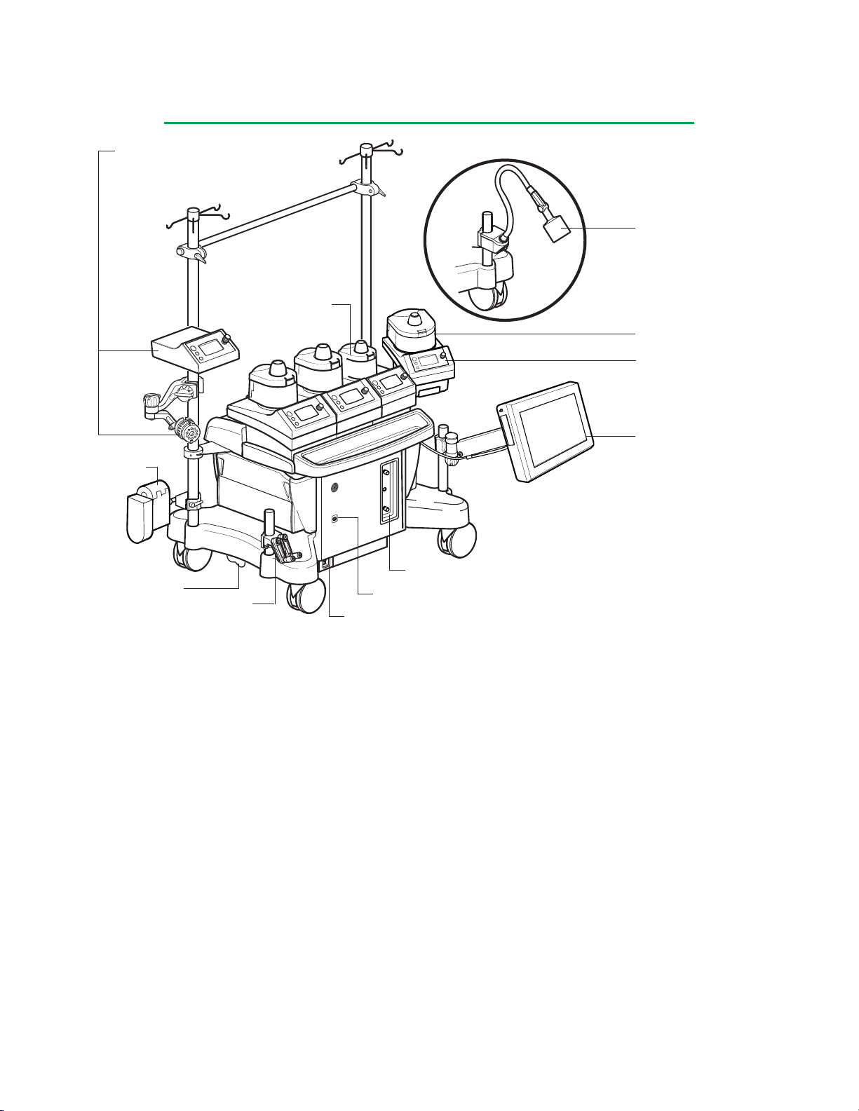
About Advanced Perfusion System 1
Centrifugal Control Unit
Local Display and Control
and Centrifugal Motor
Occluder
Lamp
Small Roller Pump
Large Roller Pump
Roller Pump Local
Display and Control
Central Control Monitor
Electronic Gas Blender Local Controls
Wheel Lock
Hand Cranks
Power Status Indicator LED
AC (Mains) Power Switch
With this system, you may…
Use Central Control from the Central Control Monitor
Integrate Pump Responses with Safety and Monitoring Systems
Choose Direction of Flow
Choose Continuous or Pulse Mode
Choose Servo Control to Pressure or Flow
Choose Master/Follower Functionality
Choose Remote Mounting of Pumps to Reduce Tube Length
Blend Gases and Monitor Gas Flow
Detect Air Bubbles and Select Pump Responses
Detect Low Blood Level and Select Pump Responses
Monitor Pressures and Select Pump Responses
Monitor Temperatures
Monitor Flow and Select Pump Responses
Monitor Cardioplegia Fluid Delivery Times and Volumes
Occlude the Venous Line
Capture Data and Events for a Perfusion Record
Display Blood Chemistry Data from CDI Devices
Operate on Battery Backup
1-1
Page 13

About Advanced Perfusion System 1
Introduction
The Terumo® Advanced Perfusion System 1 allows users to choose system
components and mounting configurations to meet current clinical needs, while
providing adaptability to reconfigure the system as their needs change. The
Advanced Perfusion System 1 may also be referred to as the System 1 throughout
this Operators Manual.
The System Base uses a distributed network to provide power and communications
to all system components. This design allows users to select the number and types
of devices needed to control and monitor patient perfusion during cardiopulmonary
bypass. These devices include any combination of the following components up to
the system maximum of 24:
Device Maximum
Electronic Gas Blender 1
Large Roller Pump 8
Small Roller Pump 8
Centrifugal Pump 2
Occluder Module 1
Air Bubble Detect Module 4
Level Detect Module 1
Pressure Module 4
Temperature Module 4
Flowmeter Module 4
CDI 100/101 Module 1
CDI 500 Module 1
Data Transfer Module 1
8 in use at any given time, 6 can
be controlled from Central Control
Monitor (CCM)
2 sensors per Module
}
1 in use at any given time
}
can be used with TLink
Management System
TM
Data
Pumps can be mounted side by side on the system base or they can be pole
mounted to reduce the lengths of tubing in the perfusion circuit. Roller pumps can
be mounted on the system base or on a pole with an appropriate mounting bracket.
The distributed network design allows modules to be plugged into any of the System
Base module receptacles. This design allows users to connect modules to any
connection point on the system base.
A Central Control Monitor (CCM) allows users to configure up to 12 different
Perfusion Screens for different equipment and protocol setups. When setting up a
Perfusion Screen, the user can define not only the system components that will be
used, but also the pump responses to safety system alerts and alarms.
In addition to monitoring system and perfusion data during a procedure, the CCM
allows touch screen control of pump speeds, gas flow and FiO2 settings (if an
electronic gas blender is installed), and occluder position. Additional advanced
functions of System 1 include Pulse Mode, Servo Control to pressure or flow, Master/
Follower functionality, and Automatic Cardioplegia Delivery.
1-2
Page 14

About Advanced Perfusion System 1
Using this manual
This Operators Manual provides directions for operating the Terumo® Advanced
Perfusion System 1.
This manual is organized to be a training tool; simply begin with this section and
proceed through the manual.
• Understand this fully integrated, adaptable perfusion system and how various
features function together and independently.
• Study the Indications and Warnings section to ascertain the system’s uses and
functional boundaries.
• Learn to start, test and customize the system.
• Learn how the pumps function.
• Learn about the safety systems.
• Learn about using the gas flow system.
• Monitor and capture perfusion data.
• Prepare for potential emergencies by studying the Emergency Procedures.
section.
• Maintain the system as directed in the Equipment Care section.
• Refer to the Additional Information section to find information on components
available for the system.
• Refer to the Technical Support section for performance information.
Note: Only trained technicians should use the Technical Support information to
make installation adjustments and replace equipment.
• Locate specific aspects of the system by using the Index.
After you have read the manual, simulate a case for practice. Simulate the emergency
situations you may encounter during perfusion and practice responding to system
messages, alarms and alerts, especially those associated with the safety systems for
air and level detection.
Note: Store product updates and instructions for system components in the inside
pocket of the manual.
1-3
Page 15

About Advanced Perfusion System 1
Indications and Warnings
Indications
The Terumo® Advanced Perfusion System 1 is indicated for use for up to 6 hours in
the extracorporeal circulation of blood for arterial perfusion, regional perfusion, and
cardiopulmonary bypass procedures, when used by a qualified medical professional
who is experienced in the operation of this or similar equipment.
The centrifugal pump is indicated for use in cardiopulmonary bypass procedures only.
Contraindications
This device is not designed, sold or intended for use except as indicated.
The centrifugal pump is contraindicated for use as a cardiotomy suction device.
User Qualications
Proper perfusion procedures and techniques are the responsibility of the medical
professional.
User must read and understand all information in the Operators Manual for the
Terumo® perfusion system being used.
System Warnings
The System 1 is indicated for use for up to 6 hours duration. The safety and
effectiveness of System 1 for long-term use (longer than 6 hours duration) has not
been established.
Use the system and any attached equipment according to the manufacturer’s
instructions and good medical practice.
This device is qualified only for durations appropriate to cardiopulmonary bypass
procedures. It has not been qualified, through in vitro, in vivo, or clinical studies, for
long-term use in bridge to transplant or pending recovery of the natural heart.
Do not use an apparently malfunctioning device in an operation.
Do not modify the Advanced Perfusion System 1 or any attached equipment or
accessories. Only use spare parts provided by Terumo Cardiovascular Systems.
Modifying the system, using unapproved spare parts, or using the system in ways
not indicated by this manual could lead to injury, compromised performance, and/or
damage.
This device must not be allowed to run unattended. Patient safety requires that
operation be properly and continuously monitored by a qualified medical professional.
System 1 is a configurable system allowing users to create perfusion screens utilizing
different combinations of equipment with different responses to events. Because
of this high degree of configurability, it is important that user institutions establish
appropriate controls to assure that users are properly trained and qualified to run
Perfusion Screens. Failure to establish such controls may result in operator
error that could result in patient injury or death.
1-4
Page 16

About Advanced Perfusion System 1
System Equipment Precautions
Grounding reliability can only be achieved when this equipment is connected to an
appropriate receptacle which has been inspected for proper grounding.
This device requires a dedicated 20 Amp AC (Mains) power source for the 100V –
120V model or a dedicated 10 Amp AC (Mains) power source for the 220V – 240V
model.
Complete any external equipment connections before turning the system on as
connecting equipment during use may cause system malfunction.
Do not use this device in the presence of explosive or flammable gases.
To avoid electrical shock hazard, do not remove panels; refer servicing to qualified
service personnel.
Do not operate the system without the module covers secured in place as spilled
liquids may damage the connections.
Connect only hospital equipment of appropriate voltage and current rating to the
auxiliary outlet.
The auxiliary outlet is not backed up by battery power. During loss of AC (Mains)
power any equipment connected to the auxiliary outlet will lose power and remain
unpowered until AC (Mains) power is restored.
Do not use extension cords to connect the system to AC (Mains) power nor to
connect modules or accessories to the system. Use of extension cords may
compromise performance.
In the event that an AC (Mains) circuit breaker trips immediately after a reset, DO
NOT attempt to reset again. The system will only operate from battery power until it
has been repaired. Call for service.
Use only the cables provided to connect pumps and flowmeter modules to the
system.
The use of accessory equipment not complying with the equivalent safety
requirements of this system may lead to a reduced level of safety of the resulting
system. Consideration relating to the choice shall include:
• use of the accessory in the patient vicinity;
• evidence that safety certification of the accessory has been performed in
accordance to the appropriate IEC 60601-1 and/or IEC 60601-1-1 harmonized
international standards.
Equipment used to heat and cool the water used to regulate the temperature of the
blood supplied to a heat exchanger should be rated Type CF. If the equipment is not
Type CF and a malfunction occurs, the possibility exists that electrical current may
pass through the heat exchanger and into the patient perfusion circuit.
The system can be stored in a ventilated area with a temperature range of 0°C to
40°C (32°F to 104°F) and a relative humidity range of 10% to 95%, non-condensing.
The system can be operated at a temperature range of 10°C to 40°C (50°F to 104°F)
at 30% to 75% relative humidity, non-condensing.
1-5
Page 17

About Advanced Perfusion System 1
Do not use chemical solvents such as ether, acetone, etc., in or on any part of the
system as such solvents may be destructive to the device. Do not disinfect with
Virex® Tb*. Do not spill anesthetics on the system or components as chemicals such
as Forane (isofluorane) may be destructive. Follow the cleaning procedure in the
Equipment Care section.
Following standard practices for electronic devices, monitor this equipment closely
when it is exposed to intense electrical noise or fluctuating line voltage. Strong
electromagnetic fields radiated from equipment elsewhere in the operating room
(particularly defibrillators and electrocautery devices) or fluctuations in AC line
voltage may compromise performance or damage the equipment.
This device needs special precautions regarding electro-magnetic compatibility
(EMC) and needs to be installed and put into service according to the EMC
information provided in the Technical Support section.
Portable and mobile radio frequency (RF) communications equipment can affect this
system.
Use only those components, transducers, or cables specified, as use of non-specified
items may result in increased emissions or decreased immunity of the system.
This system should not be used adjacent to or stacked with other equipment. If
adjacent or stacked use is necessary, observe the system closely to verify normal
operation in the configuration in which it will be used.
Read the additional Warnings and Precautions located in the appropriate sections
throughout the manual. A summary list of all the Warnings and Precautions in this
manual can be found in the Additional Information section. Use only recommended
components and meet all specifications to ensure the system will operate properly.
Copyright
Copyright © 2017 Terumo Cardiovascular Systems Corporation
This manual and the software described in this manual, are copyrighted. No part
of this manual or the described software may be copied, reproduced, translated or
reduced to any electronic medium or machine readable form without the prior written
consent of Terumo Cardiovascular Systems Corporation.
Classication
This device is classified according to UL 60601-1 as follows: Mobile, Continuous
Operation, Class 1 and Internally Powered, Type CF, Drip-Proof (with the exception of
the lamp). Not suitable for use in the presence of a flammable anesthetic.
With respect to electrical shock, fire and mechanical hazards only in
accordance with UL 60601-1, IEC 60601-1, and CAN/CSA C22.2
UL 60601-1
5P30
No. 601.1.
Patents
This device or components of this device are protected by U.S. Patents 5,752,931;
5,813,972; 6,164,920; 6,607,363; 6,609,900; 6,722,865; 6,736,617; 6,783,328;
6,971,143; 7,006,005; 7,148,786 and foreign equivalents. Other U.S. and foreign
patents pending.
* Virex® Tb is a registered trademark of JohnsonDiversy™.
1-6
Page 18

About Advanced Perfusion System 1
Training Overview
System Base
q System power (external and battery)
q Power Cord
q Power Indicator
q Powering Down
q Battery life
q Casters, wheel locks
q Poles
q Modules
qLEDs
q Channels
q Sensors
q Dedicated connections
q Pump connections
q Dedicated connections for CCM
q Dedicated connections for a lamp
q Isolated AC outlet for ancillary
equipment
q Air Filters
q Covers
q Cable Management
q Cable Cover
q Install Cover
q Remove Cover
q Occluder Subtab
q Timer Subtab
q Time/Date Subtab
q Safety Tab
q Mute Button
q Air Subtab
q Level Subtab
q Pressure Subtab
q Temperature Subtab
q Flow Subtab
q CPG Tab
q Delivery Subtab
q Auto Dose Setup Subtab
q Auxiliary Tab
q Timers Subtab
q Messages Subtab
q System Tab
q Settings Subtab
q Power Subtab
q Reassign Module Subtab
q Module Info Subtab
q Post Case Tab
q Service Area
q Shut down
Central Control Monitor
q Connection to System Base
q Start up test
q Main screen
q Configuring a perfusion screen
q Adding pumps
q Adding devices
q Safety connections
q Assigning devices
q Saving a perfusion screen
q Institutional Controls
q Password Protection
q PC Cards
q Running a case
q Message area
q Alarm
q Alert
q Status
q Error
q Mute All button
q Slide Bar Controls
q Primary Pump
q Gas System/Occluder
q Other Pumps
q Perfusion Screen Tabs
q Setup Tab
q Patient Subtab
q Gas Subtab
q Pump Subtab
Roller Pumps
q Maximum number
q Connected – 8
q Configured on perfusion screen – 6
q Large and Small
q Raceway size
q Large 6 inch (15 cm)
q Small 4 inch (10 cm)
q Flow ranges
q Tubing sizes
q Mounting and positioning (raceway
orientation)
q Accessing power
q Air Filters
q Self diagnostics
q Control
q Local
q CCM
q Local Control
q Graphic Display
q Pump Name/Module ID
q Direction icon
q Speed control knob
q Pump speed
q Flow rate display
q Alarm, alert, status, and error
messages
q Speed indicator/Bar graph
1-7
Page 19

About Advanced Perfusion System 1
q Three buttons
q Start/Stop
q Select
q Direction
q Flow Constant
q Tube Size
q Exit
q Manual
q Central Control
q Pump Icon
q Slide Bar
q Pump Tab
q Summary Subtab
q Servo Subtab
q Pressure
q Flow
q Pulse Subtab
q Master/Follower Subtab
q Tube clamp mechanism
q Setting occlusions
q Hand cranking
q Pump replacement
q Verify direction of rotation
q Operating modes
q Start
q Stop
q Continuous
q Pulse
q Master/follower
q Servo
q Roller Pump Events
q Pump Stopped
q Pump Started
q Pump Paused
q Roller Pump Responses to Alerts/
Alarms/Other Pumps
q Stop
q Pause
q Reduce speed
q Message only
q No response
q Safety Cover open, pause response
q Alarm Messages
q Alert Messages
qStatus Messages
q Error messages
Centrifugal Pump (Optional)
q Maximum number - 2
q Mounting and Positioning
q Accessing Power
q Self Diagnostics
q Control
q Local
q CCM
q Local Control
q Graphic Display
q Pump Name
q Centrifugal Icon
q Speed control knob
q Pump speed
q Flow rate display
q Alarm, alert, status, and error
messages
q Speed indicator/Bar graph
q Three buttons
q Start/Stop
q Select
q Manual
q Central Control
q Pump Icon
q Slide Bar
q Pump Tab
q Summary Subtab
q Servo Subtab
q Pressure
q Flow
q Pulse Subtab
q Min RPMs
q Setting minimum flow alarm
q Hand cranking
q Pump replacement
q Operating Modes
qStart
qStop
qContinuous
qPulse
qServo
q Centrifugal Pump Events
q Pump Stopped
q Pump Started
q Minimum Flow
q Pump goes to Coast speed
q Centrifugal Pump Responses to
Alerts/Alarms/Other Pumps
q Stop
q Coast™ Response
q Message only
q No response
q Alarm Messages
qStatus Messages
q Alert Messages
q Error Messages
Air Bubble Detect Modules and Sensors
q Maximum number – 4
q Proper positioning
q Control with CCM
q On, Off, Reset
q Connection to Devices
1-8
Page 20

About Advanced Perfusion System 1
q Roller pumps
q Centrifugal pumps
q Reset button
q Testing the ABD
q Alarm Messages
q Status Messages
q Error Messages
Level Detect Modules and
Sensors
q Maximum number – 1
q Use with Hardshell reservoirs only
q Dimensions
q Pad, sensor attachment
q Alarm/Alert Mode
q Control with CCM
q On, Off
q Connection to Devices
q Roller pumps
q Centrifugal pumps
q Testing the Level Detection System
q Alarm Messages
q Alert Messages
q Status Messages
q Error Messages
Pressure Modules and Transducers
(Optional)
q Maximum number – 8 transducers
qPlacement of transducers
q Calibration of transducers
q Pressure Display
q Setting limits
q Positive
q Negative
q Connection to Devices
q Roller pumps
q Centrifugal pumps
q Testing the Pressure System
q Servo control
q Alarm Messages
q Alert Messages
q Status Messages
q Error Messages
Temperature Modules and Probes
(Optional)
q Maximum number – 8 probes
q Probes used
q Setting alarms
q Testing the Temperature probes
q Alarm Messages
q Status Messages
q Error Conditions
Flowmeter Modules and Sensors
(Optional)
q Maximum number – 4
q Connection to Devices
q Roller pumps
q Centrifugal pumps
q Connection to centrifugal pump for
local display and min flow alarm
capability
qPlacement of Flowmeter Module
qPlacement of Flow Sensors
q Testing the Flow Sensor
qServo Control
q Alarm Messages
q Status Messages
q Error Conditions
Occluder Module and Head
(Optional)
q Maximum number – 1
q Proper insertion of tubing
q Setting up and controlling
q Tubing sizes
q Calibration
q Percent Open
q Occluder Responses to primary pump
q No Response
q Full Open
q Full Close
q Go To Flow 0% (up to 100%)
q Testing the Occluder
q Status Messages
q Error Conditions
Connecting to CDI
(Optional)
q Maximum number of CDI 500
monitors – 1
q Maximum number of CDI 100
monitors – 1
q Maximum number of CDI 101
monitors – 1
q Selecting and displaying data values
1-9
Page 21

About Advanced Perfusion System 1
Connecting to TLink™ DMS
(Optional)
q Maximum number – 1
q Collecting data
Electronic Gas Blender Module
(Optional)
q Connections
q Blending gases
q 95/5
q Air
q Control
q Manual
q CCM
q Flow Rate Range
q Oxygen Analyzer
q Calibrating the Oxygen Analyzer
q FiO2 alarm
q External Flowmeter
q Water Trap Care
q Alarm Messages
q Alert Messages
q Status Messages
q Error Messages
Primary and Backup Pumps
q Assigning Primary Pump
q Dedicated Slide Bar
q Flow Display Choices
q Pulse Mode
q Assigning Backup Pump
q Primary Pump functionality can be
reassigned
q Different pump type
q Centrifugal Coast™ responses
Cardioplegia Delivery
q Assigning cardioplegia pump
q Volume tracking
q Timers
q Time since last delivery
q Adjusting total volume delivered
q Servo Control
q Varying CPG ratios
q Delivering a fixed dose
q By Volume
q By Time
Timers
q Maximum number – 4
q Two timers preassigned
q Pump
q Clamp
q Auxiliary timers
q Timer Modes
Emergency Procedures
q Emergency situations (wet run)
q Air detected
q Low level
q High pressure
q Unexpected return to CPB
q Loss of (Hospital) gas supply
q Loss of power
q System circuit breaker
q Hospital supply
q Intermittent AC and DC
power supply
q Power failure – safety
system functions
q Local pump controls
q Local gas flow controls
q Air deprimes centrifugal pump
q Equipment situations
q Arterial pump failure
q Replacing Pumps
q Verify direction of rotation
q ABD, level failure
q Operating the system without the
CCM
q Operating the system in case of
network failure
q Centrifugal pump decouples
q Servo Loss
Equipment Care
q Cleaning and lubrication
q Preventive maintenance
q Batteries
q Power off
1-10
Page 22

System Overview
System Philosophy
The System 1 uses a software-based design and a user interface to provide an
adaptable perfusion system.
Each system device and sensor module contains software that allows it to transmit
and receive messages via a Controller Area Network (CAN). This design allows
users to:
• Connect modules to any connection point on the system base
• Enable communications links between sensors and devices
• Select how they want pumps and an occluder to respond to alert and alarm
conditions
An additional advantage of this design is the ability to use advanced functions without
requiring specialized hardware. All pumps can be configured to deliver advanced
functions such as:
Roller and Centrifugal Pumps
• Pulse mode
• Servo regulation to pressure or flow
Roller Pumps only
• Master/Follower operation
• Cardioplegia volume tracking
• Automatic cardioplegia dose delivery
The System 1 uses an intuitive patient graphic interface to organize the system
information. This centralized monitoring helps the user to view current perfusion
parameters without having to look at multiple displays.
The System 1 Central Control Monitor (CCM) also serves as the central area for
controlling pumps, an occluder, and the gas flow system. Pumps and the gas flow
system also have local controls and displays that can be used interchangeably with
the central monitor controls. This allows the user to:
• Remotely mount pumps and sensors
• Reduce tube lengths
• Reduce the prime volume of the extracorporeal circuit
2-1
Page 23
System Overview
Institutional Controls
WARNING: System 1 is a configurable system allowing users to create
perfusion screens utilizing different combinations of equipment with different
responses to events. Because of this high degree of configurability, it is
important that user institutions establish appropriate controls to assure that
users are properly trained and qualified to run Perfusion Screens. Failure to
establish such controls may result in operator error that could result in
patient injury or death.
To reduce the likelihood of such errors, user institutions should establish policies or
procedures for developing, qualifying, controlling, maintaining and securing perfusion
screen configurations. The following list includes suggested actions to be covered by
such procedures. This is not intended as an all-inclusive list of actions, but is merely
a guide to illustrate examples of what an institution should consider when using
System 1. Additional or different actions may be necessary depending on particular
use and/or institutional policies and procedures.
Suggested policies and/or procedures to be established:
• Authorization of appropriately qualified individuals to create, revise and approve
Perfusion Screens.
• Use of passwords to prevent unauthorized changes to Perfusion Screens.
• Testing methods to assure all system responses are completely understood and
meet expectations.
• Establishment of protocols or methods for responding to situations that may
occur during use.
• Establishment of a standard system direction for roller pump forward flow.
• Establishment of a policy to re-set the roller pump default direction to the
institution’s chosen standard system direction. This particularly applies to
replacement, loaner or returned pumps.
• Training of users.
2-2
Page 24
System Overview
System Base
Features
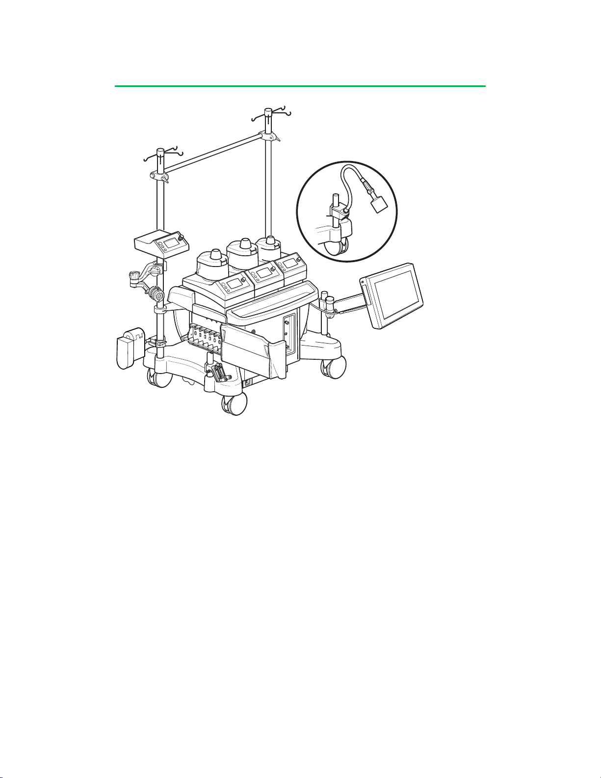
The system base houses the internal network architecture, electronics, power supply
components, batteries, communications and power connections and circuit breakers.
The base has a pair of casters on each side. Each pair of casters has a 3 position
locking lever to control the movement of the casters.
Roller pumps are mounted along a central rail on the top of the base or on the
poles with mounting brackets. There are 2 sizes of pump mounting extensions to
allow different combinations of large and small pumps to be mounted along the
central mounting area. Cable clips are built in to the mounting area to aid in cable
management. The centrifugal control unit is mounted on the system with a pole
mounting bracket.
Modules are connected to the receptacles on the sides of the base. A locking rail
protects the modules from accidental disconnection.
Protective cover panels are attached to the top and sides of the base after
components are installed to protect cables and components from liquid spills.
Long mounting poles are installed on the back corners of the base and short
mounting poles are installed on the front corners of the base. A crossbar can be
mounted between the 2 longest poles.
A pole-mountable lamp is available in 2 sizes, long or short.
A hand crank bracket, which holds 2 hand cranks, can be mounted on a pole in a
convenient location.
There is an auxiliary outlet on the back of the system base for powering additional
equipment.
2-3
Page 25
System Overview
Central Control Monitor
Features
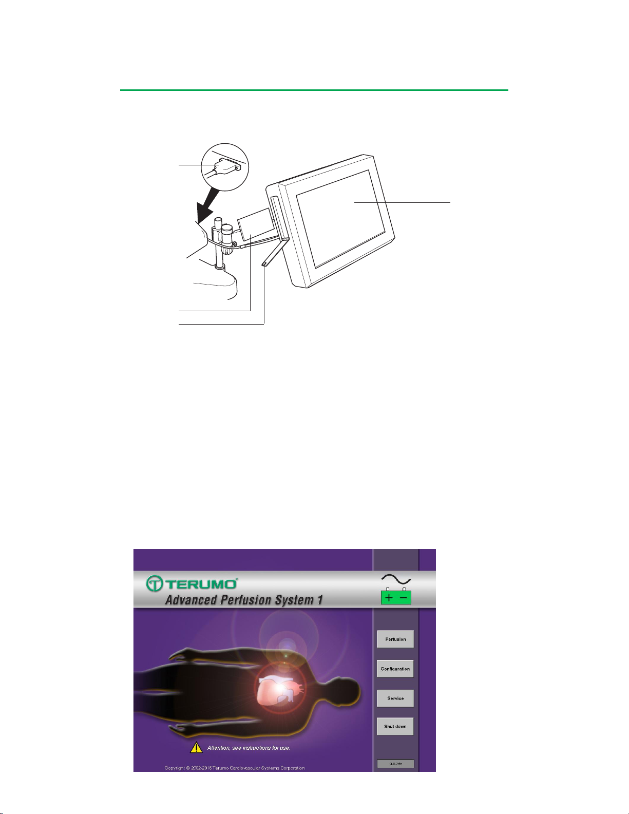
Power Cable Connection
PC Cards
PC Card Door Latch
The Central Control Monitor (CCM) is the primary control and monitoring center for
the Advanced Perfusion System 1. The CCM comprises an embedded computer with
an integrated graphical display and a touch screen.
Display Area
A power cable connects the Central Control Monitor to the system.
The Central Control Monitor holds 2 PC Cards: a system configuration card and a
service data card. The system configuration card may be used to transfer perfusion
screen configurations between systems. The service card collects and stores data
for use by authorized service representatives. Service cards should be handled only
by qualified service technicians.
Display Areas
Main Screen
The Main Screen is the first screen that is displayed after the system completes
initialization and a self test. If any device fails the start up test, a failure message will
be displayed at the top of the screen.
2-4
Page 26
System Overview
Perfusion Screen
Open
View Summary >
Return to Main
Name
Password:
Choose a Perfusion Screen
CABG Roller
CABG Centrif
Yes
Yes
Min AVR
No
Circ-ARREST
Yes
Pediatric
No
CABG ROLLER
Perfusion Screen Summary
Graphic Orientation:
Primary Pump Left - Patient Head Left
Blood Reservoir Type:
Open
Air Detectors:
ART Air
Level Detectors:
Level
Occluders:
Occluder
Pressure Sensors:
ART Pres
CPG Pres
Temperature Sensors:
ART Temp
VEN Temp
Bladder
CPG1 Temp
CDI 500:
CDI 500
Large Roller Pumps:
Arterial
Safety Connections:
Device Event Response
Level Low Level Alarm Stop
Level Low Level Alert Message 0nly
ART Air Air Detected Alarm Stop
ART Pres High Presure Alarm Stop
ART Pres High Presure Alert Message 0nly
CPG
Safety Connections:
Device Event Response
Arterial Pump Stopped Stop
Arterial Pump Paused Stop
CPG Press High Pressure Alarm Stop
CPG Press High Pressure Alert Message Only
Small Roller Pumps:
Vent
Sucker 1
Sucker 2
Timers:
Pump
Clamp
TMR1
Close
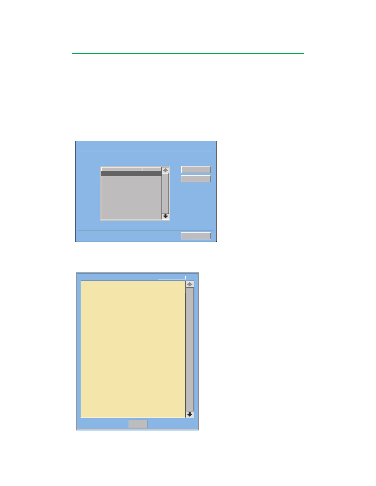
The system software version can be viewed on the lower right side of the Main
Screen. Four buttons, Perfusion, Configuration, Service, and Shut down allow
access to the functional areas or provide a controlled shut down of the system
computer before turning the AC (Mains) power off to the entire system.
Perfusion
A Perfusion Screen is a graphical representation of the perfusion circuit on the CCM
touch screen that is used to control and monitor perfusion parameters during a case.
The Perfusion area allows the user to select a Perfusion Screen for running a case.
The initial screen lists all the Perfusion Screen names and their password protection
status.
A Configuration Summary can be viewed for each Perfusion Screen or the desired
screen can be selected and opened.
Perfusion Screens are created or modified in the configuration area. If desired,
access to a Perfusion Screen can be limited by assigning a password.
2-5
Page 27
System Overview
Setup Safety CPG Aux System
Post Case
Power Source/Battery Status Icon
Select Primary Pump Displa
TM
CDI
Venous
Shared Slide Bar Area
Occluder
FiO2 (if installed)
Gas Flow (if installed)
Fine Adjustment Arrow
Device Icon
Reservoir
Oxygenator
Gas Icon
Primary Pump Slide Bar
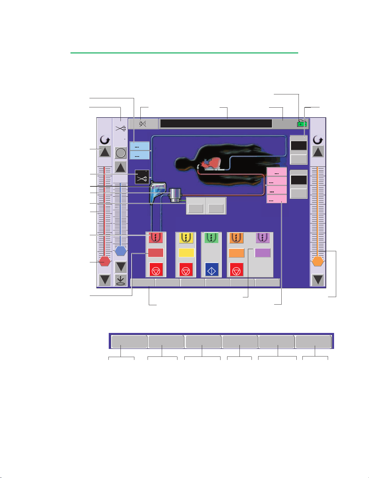
The illustration below is an example of a Perfusion Screen -the different elements
and areas of the Perfusion Screen are labeled. For detailed information about
the function of the Perfusion Screen, refer to the Perfusion Screen section of the
Central Control Monitor chapter.
Arterial
0.000
L/min
10.78
Occluder
0
%Q
100
SO2
HCT
0
Mute All
%
%
%Q
Message Area
Gas
% O2
0
80.0
Time of Day
16:07:51
pH
PO2
mmHg
PCO2
mmHg
K+
mmol/L
Pump
000:00
Reset
Reset
Clamp
000:00
Reset
Reset
Timer
CPG1
0.000
L/min
2.00
Pump Tab
Pulse (Primary Only)
Servo
Scroll Control
L/min
L/min/m
mL/kg/min
CDI
CPG2
0.000
0.00
L/min Total
Post Case
TM
Arterial
1:1
0
Shared Pump
Slide Bar
Arterial
0.000 0.000
0
0
Setup
L/min
STOP
Safety
y
2
Tabs
Vent
L/min
STOP
CPG
Sucker1
L/min
START
Aux System
CPG1
0.000
L/mi
n
STOP
Activates Shared Slide Bar
Tabs and Subtabs
Setup
Patient
Gas
Pumps
Occluders
Timers
Time/Date
Safety
Air
Level
Pressures
Temps
Flow
CPG
Delivery
Auto Dose Setup
Aux
Timers
Messages
System
Settings
Powe r
Reassign Module
Module Info
Post Case
End Case
2-6
Page 28
System Overview
System Settings
Language:
English
Date Format:
dd/mm/yyyy
Roller Pump Direction:
Configuration
Change Settings >
Edit Config Password >
PC Card Utilities >
New
Edit
View Summary >
Rename >
Set Password >
Delete
Return to Main
Name
Ready:
Last Edit:
Password:
Perfusion Screens
Yes
15/05/2002
Yes
15/05/2002
CABG Roller
CABG Centrif
Min AVR
No
Circ-ARREST
Yes
Pediatric
No
15/05/2002
15/05/2002
15/05/2002
Password
Configuration
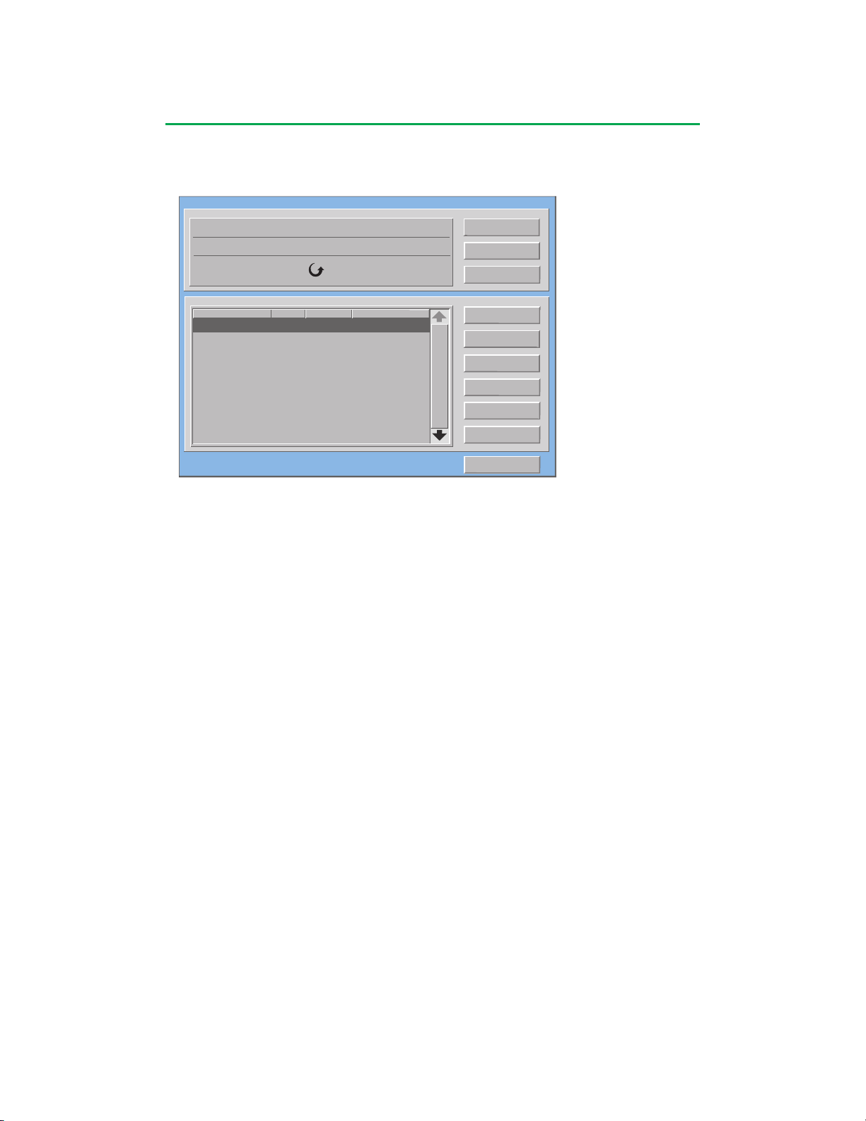
The Configuration area can be password protected and allows authorized users to
view and change system settings and Perfusion Screens.
The System Settings area is used to select the display language, the date format,
set the default system direction for roller pumps, edit the configuration password, and
access the PC Card Utilities.
The PC Card Utilities are used to move or copy Perfusion Screen files between the
CCM and a PC Card, view a Perfusion Screen Summary, and rename or delete a
Perfusion Screen.
The Perfusion Screens area is used to create, edit, rename, or delete perfusion
screens. A Perfusion Screen Summary can be viewed and a password can be
assigned to the screen in order to limit access to authorized users.
When creating a new Perfusion Screen, the user is led through a step by step
process:
• Selecting primary pump and patient orientation
• Selecting additional pumps including on screen names and colors
• Selecting additional modules including names and, if available, colors
• Establishing safety connections
• Setting alert and alarm limits
• Selecting pump responses to external events
• Selecting occluder responses to primary pump events
• Assigning screen representation to physical modules and devices
• Naming the Perfusion Screen and identifying the screen as ready for use
For more details on the operation of the Configuration area, refer to the
Configuration section of the CCM chapter.
Service
Access to the Service area is password protected and limited to authorized
personnel. This area is used to view the system log, export the system log to an
external computer via the service data card, view module error event data and
calibrate the touch screen. It is also used to manage security access control and
view the system software version control area.
Shut down
Provides a controlled shut down of the system computer and must be performed
before AC (Mains) power to the entire system is turned off. Failure to follow the
controlled shut down procedure may result in improper start-up at the next power-on.
2-7
Page 29
System Overview
ARTERIAL 1/2
L/min
4.50
Roller Pumps
Features
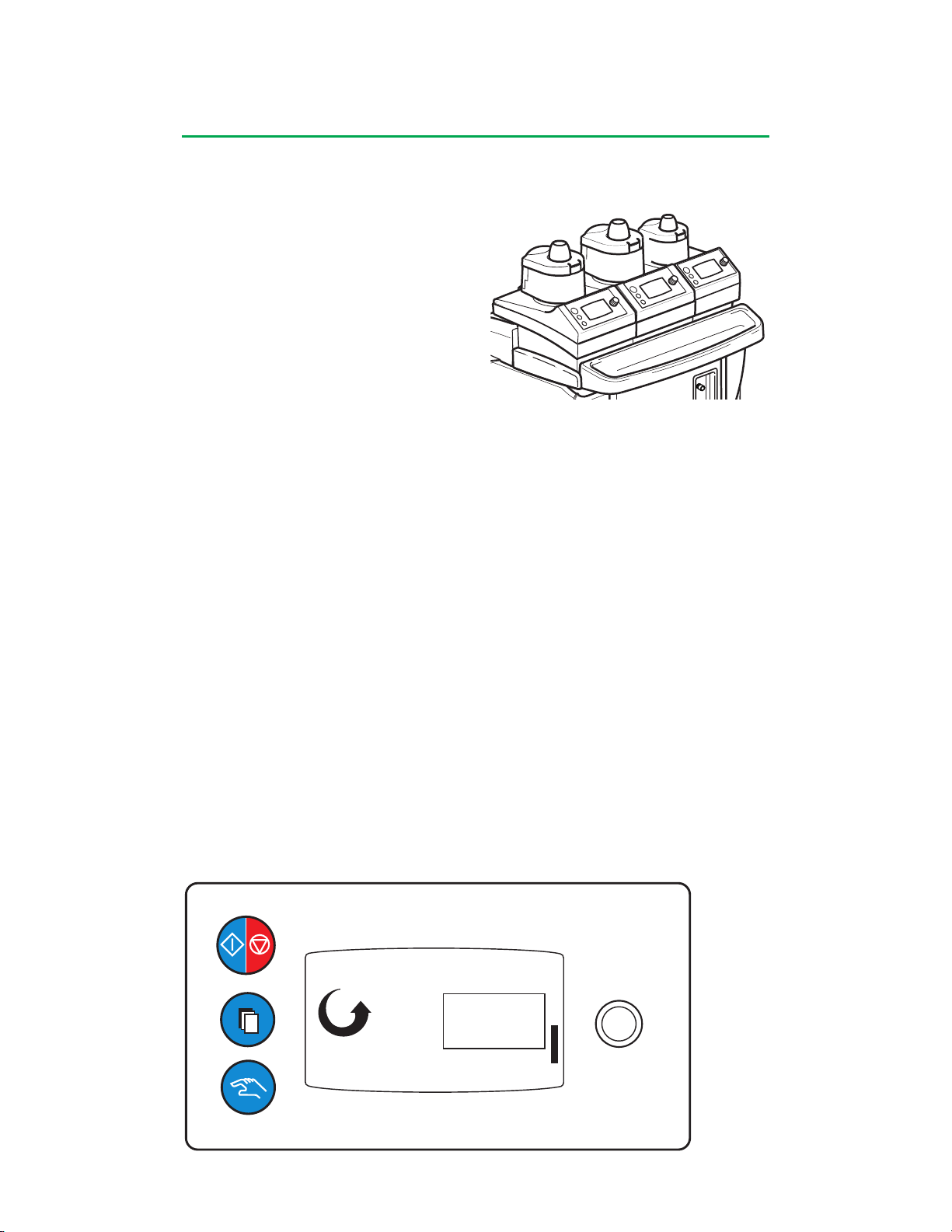
Roller pumps are available in 2 sizes.
Large roller pumps have a 6 inch
(15 cm) raceway and small roller
pumps have a 4 inch (10 cm) raceway.
Large roller pumps can be used for
arterial, cardioplegia, vent and suction
applications. Small roller pumps can be
used for pediatric arterial, cardioplegia,
vent and suction applications.
Pumps can be mounted side by side on the system base or they can be pole
mounted to reduce the lengths of tubing in the perfusion circuit. Roller pumps can
be mounted on the system base or on a pole with an appropriate mounting bracket.
Various arrangements of large and small pumps can be mounted on the system base
using the mounting extensions provided.
Roller pumps are connected to the system with a cable. There are 6 pump
receptacles on the system, 3 on each side. Roller pumps can also be connected to
any of the module receptacles. Up to 8 pumps can be connected to the system, but
only 6 can be controlled through the Central Control Monitor at any given time.
The roller pump raceway can be rotated in 15° increments and locked into position
to allow for options to reduce tubing length. A universal tube clamp mechanism
accommodates a variety of tubing sizes, including dual tubing sets, without the need
for different size inserts.
The occlusion mechanism allows the position of the rollers to be adjusted at any time,
including while the pump is rotating. An audible click can be heard whenever the
occlusion is being adjusted.
Roller pumps can be controlled from the Central Control Monitor or from controls
on the pump itself. Tubing size, direction of rotation, speed, flow rate or RPMs, and
safety, status and error messages are displayed on the pump as well as on the
Central Control Monitor. An amber colored bar graph represents pump speed.
2-8
Page 30

System Overview
There are 5 operating modes for a roller pump:
• Continuous: the pump operates at a constant speed set by the user.
• Pulse: available on the primary pump only; the pump speed alternates between
a peak speed and a baseline speed. Base, Rate and Width can be adjusted
through the Central Control Monitor.
• Master/Follower: set up during configuration; involves two roller pumps in
Continuous Mode. The Follower pump demand flow rate or speed is a percentage
of the master pump flow rate or speed. The percentage can be adjusted
through the Central Control Monitor or from the pump speed control knob on the
follower pump. The pump designated as the primary or arterial pump cannot be
designated as a master/follower pump.
• Servo Control: pump speed is regulated to maintain a specific pressure or flow
rate. The pressure and flow rate setpoints can be adjusted through the Central
Control Monitor or from the pump speed control knob on the pump.
• Automatic Delivery: the pump delivers a set fluid volume or delivers fluid for a set
amount of time and then stops.
Roller pumps can be connected to safety and monitoring systems and other pumps
during configuration, followed by choosing pump responses. Roller pump response
choices are No Response, Stop, Pause, Reduce Speed and Message Only. The
choices allowed for a pump response vary depending on the type of alert or alarm
and the type of device connected to the pump.
When a connected device is in alert or alarm mode, a message will display on the
pump display.
Centrifugal Control Unit
Features
The centrifugal control unit provides an interface between the system and a
centrifugal drive motor. A disposable centrifugal pump magnetically couples to the
drive motor. The drive motor is mounted on a pole and connects to the centrifugal
control unit with a cable. The centrifugal control unit mounts on a pole and connects
to the system with a cable. The control unit can be connected to a pump receptacle
or to any of the module receptacles.
Up to 2 centrifugal control units can be connected to the system at a time. The
centrifugal pump can be controlled from the Central Control Monitor or from controls
on the centrifugal control unit.
2-9
Page 31
System Overview
ARTERIAL
2010 RPM
L/min
4.50
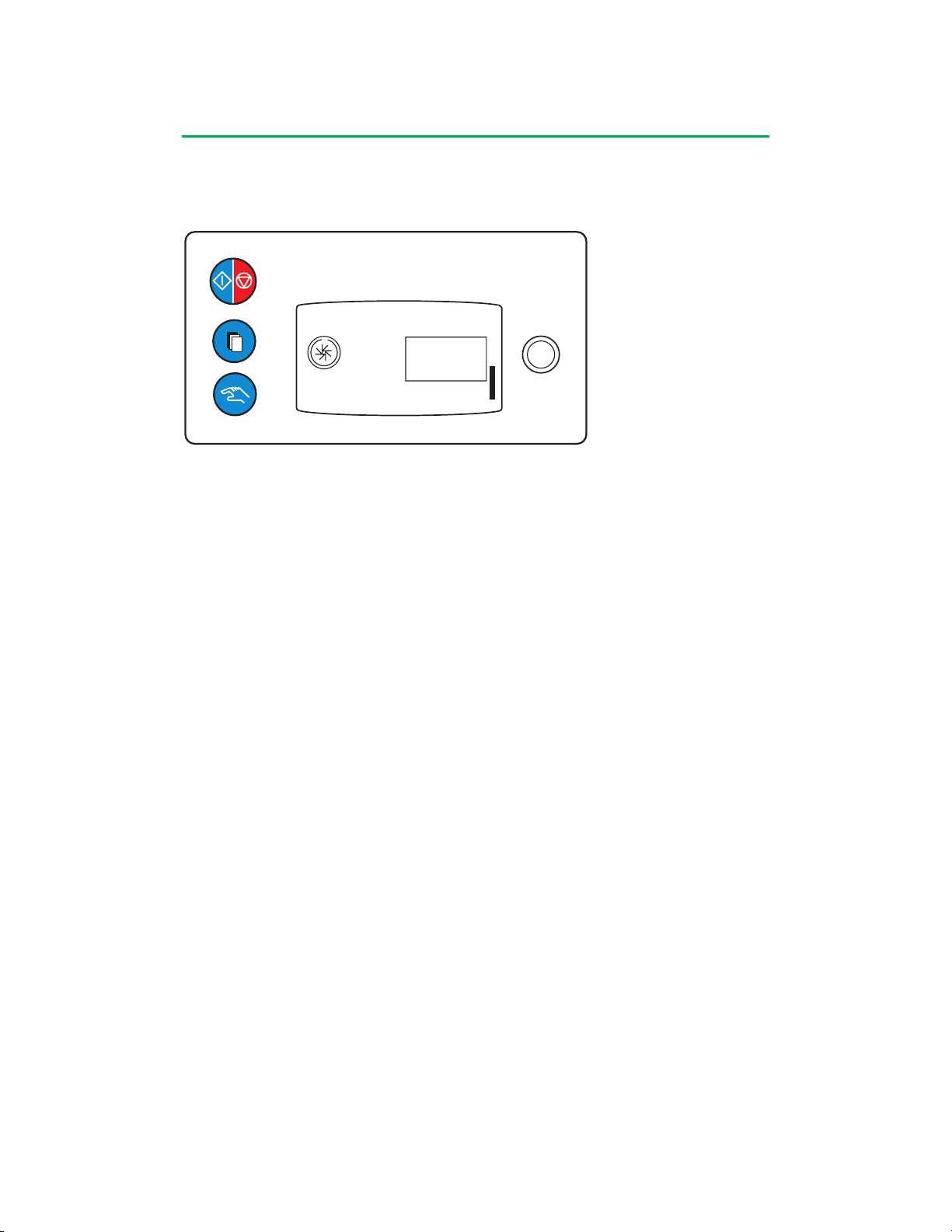
Motor speed, flow rate, as well as safety, status, and error messages are displayed
on the centrifugal control unit control panel as well as on the Central Control Monitor.
Pump speed is displayed in RPMs on the pump as well as represented as an amber
colored bar graph.
There are 3 operating modes for a centrifugal pump:
• Continuous: pump operates at a constant speed set by the user.
• Pulse: available on the primary pump only; the pump speed alternates between a
peak speed and a baseline speed. The baseline speed can be adjusted through
the Central Control Monitor.
• Servo Control: pump speed is regulated to maintain a specific pressure or flow
rate. The pressure and flow rate setpoints can be adjusted through the Central
Control Monitor or from the pump speed control knob on the centrifugal control
unit.
The centrifugal system can be connected to safety and monitoring systems and other
pumps during configuration, followed by choosing centrifugal control unit responses.
Centrifugal control unit response choices are No Response, Stop, Coast and
Message Only. The choices allowed for a pump response vary depending on the type
of alert or alarm and the type of device connected to the pump.
When a connected device is in alert or alarm mode, a message will display on the
centrifugal control unit display.
2-10
Page 32
System Overview
Modules
Features
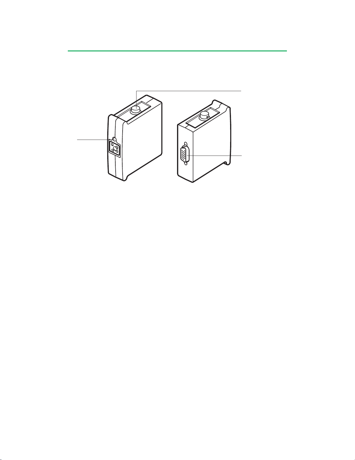
Sensor Connection
LED
System Connection
The following modules connect to the system: Air Bubble Detect, Level Detect,
Occluder, Temperature, Pressure, Flowmeter, Interface Module for CDI 100/101,
Interface Module for CDI 500, and Interface Module RS-232.
Modules provide an interface between an appropriate type of sensor or device and
the system.
Each module has appropriate connections for the type of sensor needed.
Each module has a tricolor LED (light emitting diode) to indicate module status.
Status modes are:
Constant Green – Online Mode Blinking Yellow – Alert Condition
Blinking Green – Assignment Mode Constant Red – Broken Mode
Constant Yellow – Offline Mode Blinking Red – Alarm Condition
Up to 18 modules can be connected to the system; 9 on each side.
Modules are connected directly to the receptacles on either side of the system, with
the exception of the flowmeter module, which is mounted on a bracket and connected
to the system by a cable from the module.
2-11
Page 33
System Overview
Air Bubble Detect Module
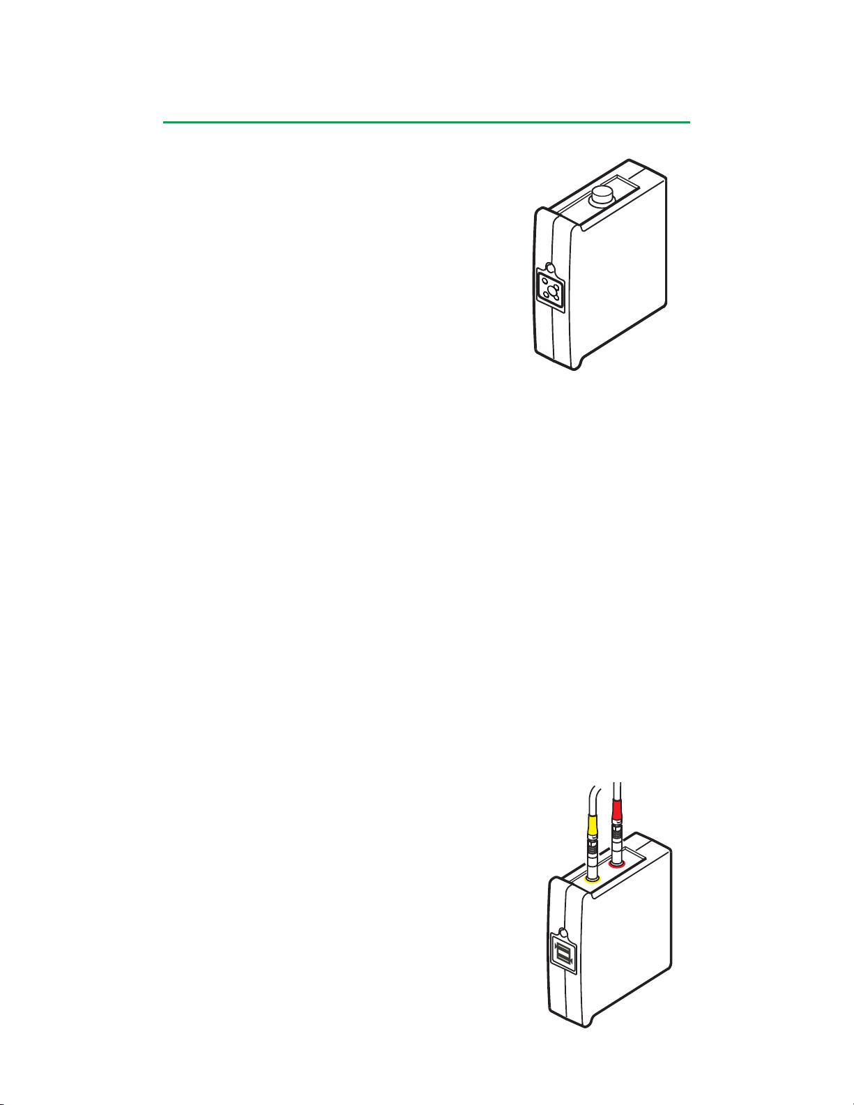
The air bubble detect module (ABD) is used with an air
sensor to detect air bubbles in the perfusion circuit. Use
only Terumo® SarnsTM Ultrasonic Air Sensors with the
system.
Up to 4 air bubble detect modules may be connected to
the system at the same time.
The air sensor connects to the module with the air
sensor cable. The air sensor can be mounted directly on
the tubing or on a bracket.
Select the sensor which is appropriate for the tubing size
and flow rate to be used.
Tubing size can be 3/8 in (9,5 mm) I.D. (Inner Diameter) x 3/32 in (2,4 mm) wall
thickness, 1/4 in (6,4 mm) I.D. x 3/32 in (2,4 mm) wall thickness or 1/4 in (6,4 mm) I.D.
x 1/16 in (1,6 mm) wall thickness.
The air sensor detects air bubbles within clear, flexible medical grade polyvinyl
chloride (PVC) tubing in clear priming solutions or blood with a hematocrit from 15%
to 40%.
The air sensor detects air bubbles of 0.3 cc or larger at flow rates up to 3 L/min for
1/4 in (6,4 mm) I.D. tubing and gas bubbles of 0.5 cc or larger at flow rates up to 6
L/min for 3/8 in (9,5 mm) I.D. tubing.
The air bubble detect module only operates in the alarm mode. Pump responses to
an air alarm are selected during configuration.
In the event of an alarm, an audible dual tone alarm sounds, a message appears on
the Central Control Monitor, the appropriate air detect icon on the Central Control
Monitor flashes red, and the status LED on the appropriate air bubble detect module
flashes red. If a safety connection was made to a pump, a message will also appear
on the message area on the pump control panel, and the pump will react with the
response chosen.
Level Detect Module
Always use a level detect module with level sensors to
monitor blood levels in hardshell reservoirs. Use only
Terumo® SarnsTM Ultrasonic Level Transducers with the
system.
One level detect module may be connected to the
system.
Level sensors are attached to the color coded
connectors on the module and then to a hardshell
reservoir. A yellow alert sensor attaches to the yellow
connector and a red alarm sensor attaches to the red
connector. Level sensors are attached to the hardshell
reservoir with level sensor pads.
2-12
Page 34
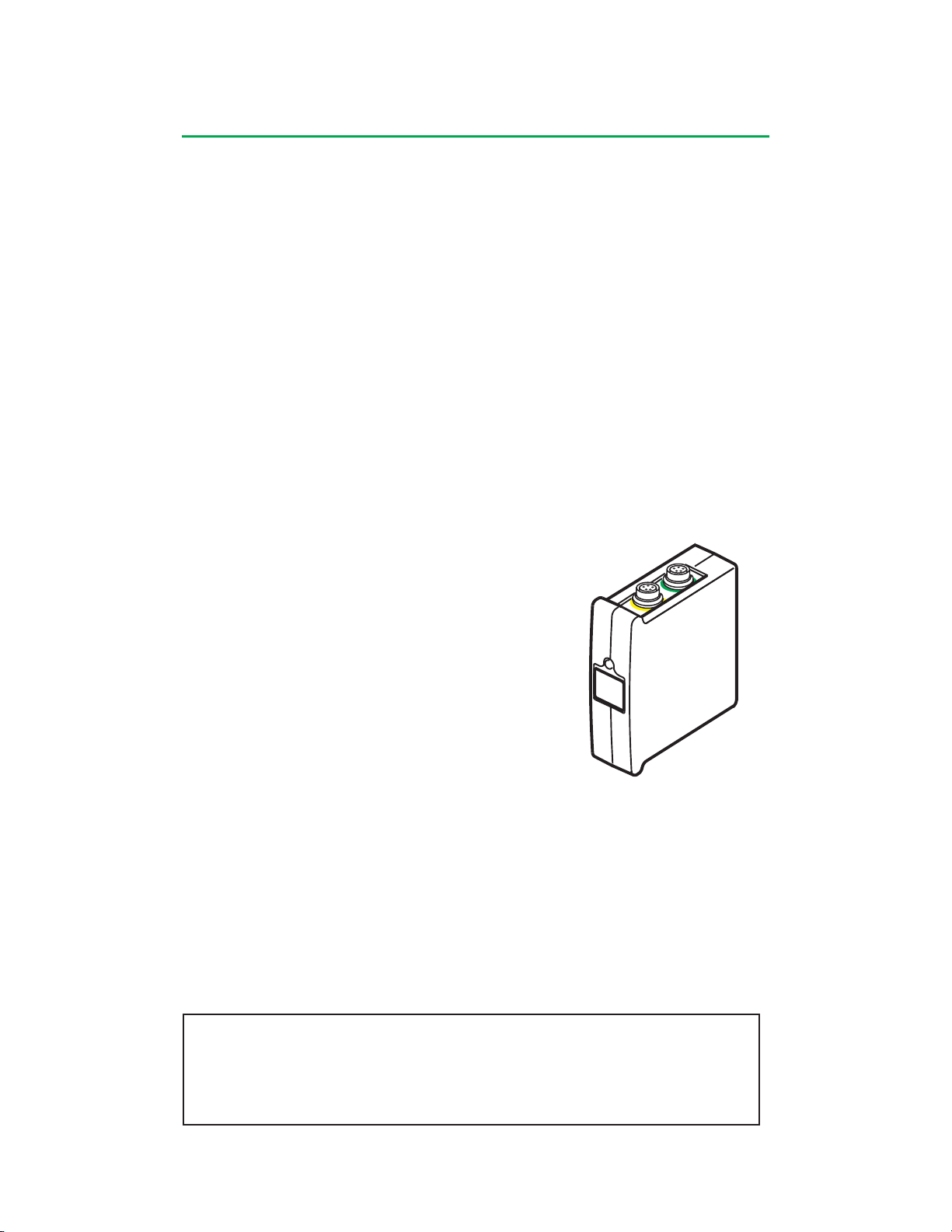
System Overview
mmHg
The hardshell reservoir must be made of polycarbonate material with wall
thicknesses of 0.07 inches (1,8 mm) – 0.15 inches (3,8 mm). Level sensors should
be placed so that internal structures of the reservoir are more than 1 cm away from
the transducer face. The level sensors function normally with clear priming solutions
and blood of any hematocrit.
An operating mode for the module of Alert Only or Alert and Alarm is selected during
configuration. The operating mode can also be changed during a case.
In the event of an alarm, an audible dual tone alarm sounds, a message appears
on the Central Control Monitor, the level detect icon on the Central Control Monitor
flashes red and the status LED on the level module flashes red.
In the event of an alert, an audible single tone alert sounds, a message appears
on the Central Control Monitor, the level detect icon on the Central Control Monitor
flashes yellow and the status LED on the level module flashes yellow.
In the event of an alert or alarm, if a safety connection was made to a pump, a
message will also appear in the message area on the pump control panel, and the
pump will react with the response chosen.
Pressure Module
The pressure module provides the interface between
pressure transducers and the system. Each pressure
module has 2 channels. Two pressure transducers can
connect to each pressure module.
Up to 4 pressure modules can be connected to the
system at a time.
Terumo offers pressure transducers known to be
compatible for use with the pressure module.
Pressure transducers must be calibrated before use.
Pressure alarm limits, alert limits, safety connections and pump responses are set up
during configuration. Pressure information can be viewed and changed through the
Safety tab on the case screen.
The System 1 is capable of displaying pressure values between –250 mmHg and
+900 mmHg. Information is displayed on the Central Control Monitor in the perfusion
screen, in a square icon labeled mmHg.
“CAL” will be displayed if the pressure transducer requires calibration, “– – –”
is displayed at pressures less than –250 mmHg or if no pressure transducer is
connected, “999” is displayed at pressures greater than +900 mmHg. The display is
blank in the event of a module malfunction.
CAUTION: The accuracy of the pressure information is dependent on
the specification of the pressure transducer. Always ensure the pressure
transducers used are appropriately specified for the application. Refer to
instructions for use provided with the pressure transducer for the transducer’s
specifications.
2-13
Page 35
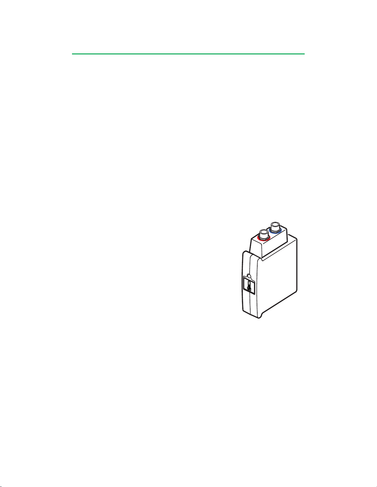
System Overview
If a pressure module has been configured to operate with a pump in servo mode,
pressure information will also be displayed on the pump control panel display during
servo operation.
In the event of a pressure alarm, a dual tone audible alarm sounds, a message is
displayed on the Central Control Monitor, the appropriate icon turns red and flashes,
and the status LED on the appropriate pressure module flashes red.
In the event of a pressure alert, a single tone audible alert sounds, a message is
displayed on the Central Control Monitor, the appropriate icon turns yellow and
flashes, and the status LED on the appropriate pressure module flashes yellow.
In the event of an alert or alarm, if a safety connection was made to a pump, a
message will also appear in the message area on the pump control panel, and the
pump will react with the response chosen.
In the event of overrange/underrange readings or pressure system malfunction,
physiological alerts or alarms are cleared automatically. If a safety connection from
a pressure event had paused or stopped a pump, that pump can then resume or be
restarted (if no other pause or stop responses are in effect). If the pressure reading
returns into range between -250 mmHg and +900 mmHg inclusive, the physiological
alerts or alarms will reoccur as appropriate.
Temperature Module
The temperature module provides the interface
between temperature sensors and the system. In order
to maintain electrical isolation in accordance with
applicable standards, insulated temperature probes must
be used.
YSI Series 400 compatible probes, with the exception
of Model 416, must be used in order to monitor
temperature properly with System 1.
Each temperature module has 2 channels. Two temperature
sensors can connect to each temperature module.
Up to 4 temperature modules can be connected to the system at a time.
Temperature information is displayed on the Central Control Monitor in the perfusion
screen, in a rectangular icon labeled °C. The display will show – – – if no sensor is
attached.
A high temperature alarm can be set for each temperature sensor.
In the event of a temperature alarm, a dual tone audible alarm sounds, a message
is displayed on the Central Control Monitor, the appropriate icon flashes red, and the
status LED on the temperature module flashes red.
2-14
Page 36
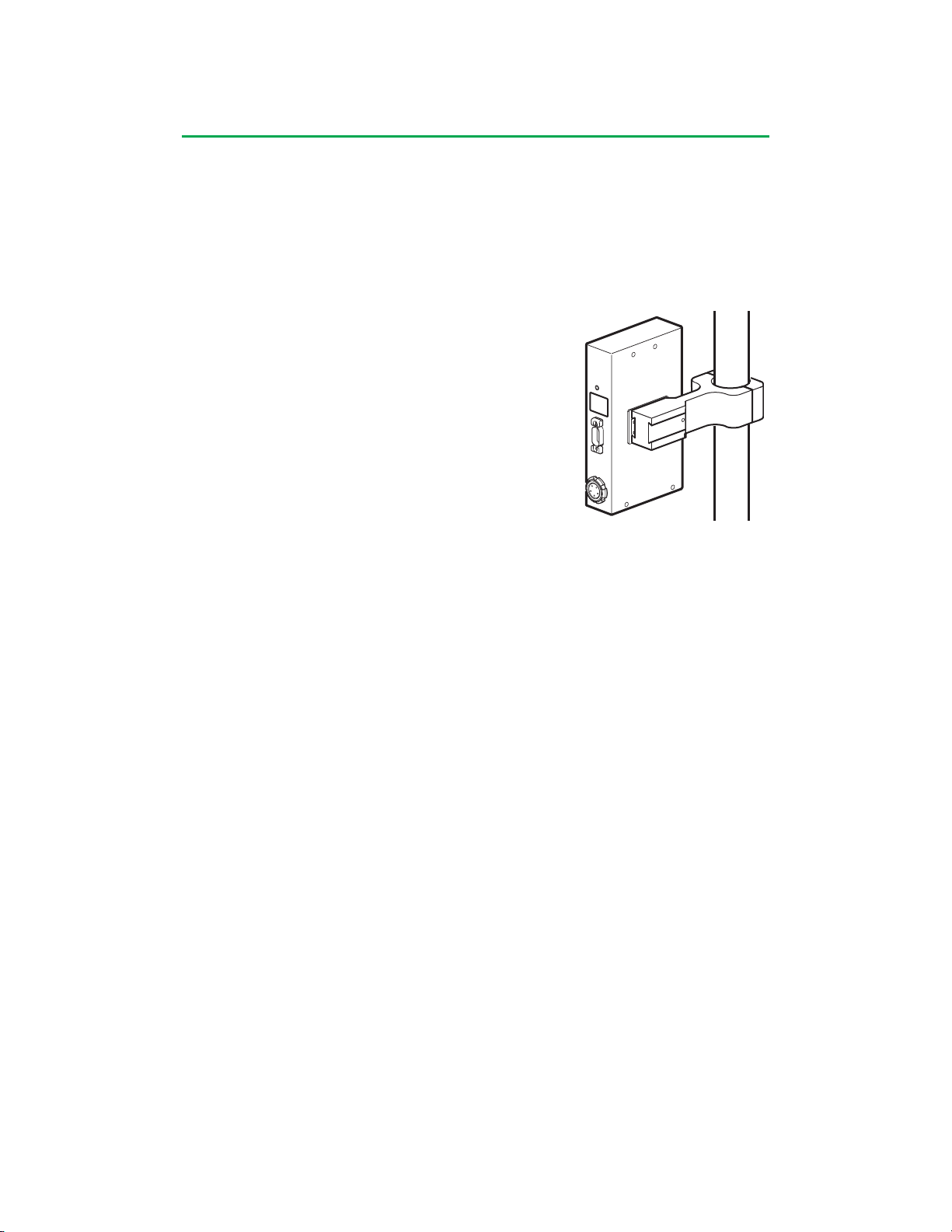
System Overview
L/min
Flowmeter Module
The flowmeter module provides the interface between
an ultrasonic flow sensor and the system. Up to 2
flowmeter modules can be mounted on each flowmeter
mounting bracket. Up to 4 flowmeter modules can be
connected to the system at a time.
It is recommended that a flowmeter module always be
used when a centrifugal pump is used.
Flow information is displayed in a rectangular icon, in
L/min, on the Perfusion Screen. Placement of the icon
is chosen during configuration. If the flowmeter has
been placed on a centrifugal pump, flow data will also
be displayed on the centrifugal control unit display and
the minimum flow alarm will be functional.
For centrifugal pumping, a minimum flow alarm can be
set to warn of reduced flow. In the event of a minimum
flow alarm, a dual tone audible alarm sounds, a message is displayed on the Central
Control Monitor and on the control panel of the centrifugal control unit.
The flowmeter module generates an alarm when backflow is detected. In the event of
a backflow alarm, a dual tone audible alarm sounds, a message is displayed on the
Central Control Monitor, the appropriate icon turns red and flashes (unless the icon
was placed on a centrifugal pump), and the status LED on the appropriate flow meter
module flashes red. If a safety connection was made to a pump, a message will also
appear on the pump control panel and the pump will react with the response chosen.
2-15
Page 37
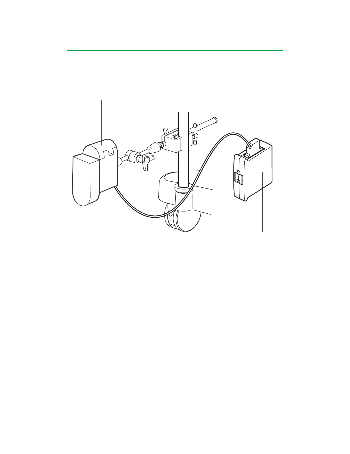
System Overview
Occluder Head
Occluder Module
The occluder module is used with the occluder head to provide a computer-controlled
tube clamping mechanism to regulate the flow in the venous line. The occluder head
is attached to the module with the occluder head power cable.
Occluder Module
Only 1 occluder may be connected to the system.
Tubing is positioned in the occluder head and is compressed by a plunger. Tubing
can range in size from 1/4 in (6,4 mm) I.D. x 1/16 in (1,6 mm) wall thickness to 1/2
in (12,7 mm) I.D. x 3/32 in (2,4 mm) wall thickness with a recommended nominal
durometer range of 65-70 Shore A.
The occluder is controlled through the occluder slide bar on the Central Control
Monitor. Use the Open and Close buttons on the slide bar or choose a percentage
open by using the scroll control. There are no local controls on the occluder head.
The occluder must be calibrated prior to use. The occluder icon on the Central
Control Monitor will display “CAL” to indicate that the occluder needs calibration.
2-16
Page 38

System Overview
Interface Modules
Interface Module for CDITM 100/101
The Interface Module for CDITM 100/101 provides an interface between the system
and a CDITM 100 or 101 Extracorporeal Hematocrit/Oxygen Saturation Monitor*. The
module is connected to the CDITM 100 or CDI™ 101 monitor with a serial cable.
Data from the CDITM 100 or CDI™ 101 monitor can be configured to be displayed on
the Central Control Monitor. Parameters that can be displayed are oxygen saturation,
hematocrit and hemoglobin.
Interface Module for CDITM 500
The Interface Module for CDITM 500 provides an interface between the system and
a CDITM 500 Blood Parameter Monitoring System. The module is connected to the
CDITM 500 monitor with a serial cable.
Data from the CDITM 500 monitor can be configured to be displayed on the Central
Control Monitor. Parameters that can be displayed are arterial PO2, arterial PCO2,
arterial pH, arterial temperature, arterial oxygen saturation, bicarbonate, base
excess, venous PO2, venous PCO2, venous pH, venous temperature, venous
oxygen saturation, potassium concentration, oxygen consumption, hemoglobin, and
hematocrit.
The CDITM 500 monitor receives flow data from System 1. The flow data is displayed
on the front of the CDITM 500 monitor and is used to calculate and display the O2
consumption.
Interface Module RS-232
Data Transfer
The Interface Module RS-232 provides an interface between the system and the
TLink™ Data Management System. The module is connected with a serial cable to
the serial port on the computer on which the perfusion software has been installed.
During a case, perfusion data and events from System 1 are sent through the
Interface Module to be captured by the perfusion software.
* The Terumo CDI™ 101 Hematocrit/Oxygen Saturation Monitoring System is not cleared for marketing
in the United States by the US Food and Drug Administration (FDA).
2-17
Page 39
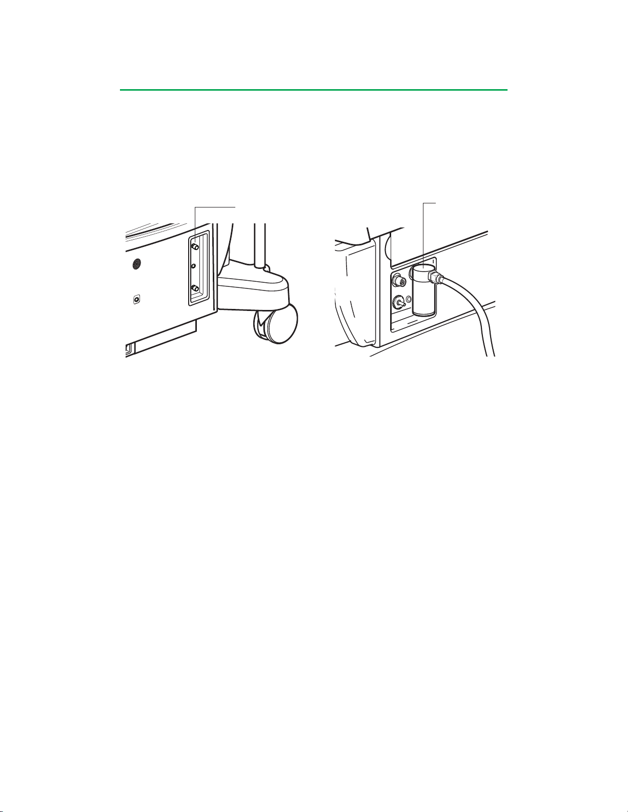
System Overview
Electronic Gas Blender
The electronic gas blender is a module that is internally installed in the system base.
The gas blender provides control and monitoring of the gas output to an oxygenator.
An integrated oxygen analyzer measures the oxygen content of the gas blend.
Electronic Gas Blender
Controls
Front Panel Back Panel
The oxygen analyzer requires, at a minimum, daily calibration and can be calibrated
from the Central Control Monitor.
An air or 95% oxygen/5% carbon dioxide (95/5) inlet, an oxygen inlet, a gas outlet,
and an exhaust port are on the back of the system base. Use only medical grade
gases supplied at an inlet pressure of 50 psi ± 20 psi with the difference between the
two inlet gas pressures being no more than 18 psi.
Water trap
The gas blender can be controlled from the Central Control Monitor by using the Gas
and FiO
flow information is displayed on icons labeled Gas, %O2 and FiCO2, if appropriate, on
the Perfusion Screen. An external, mechanical flowmeter, provided in the accessory
kit, should be connected to the gas outlet and be positioned between the vaporizer
and the oxygenator to monitor the gas flow in the event Central Control Monitor
capability is lost.
An alarm limit for Low FiO2 can be chosen during case setup.
High and low pressure alarms are generated by the system if the inlet pressure of a
source gas exceeds 70 psi or falls below 30 psi. In the event of a pressure alarm, a
dual tone audible alarm sounds and an alarm message is displayed on the Central
Control Monitor.
slide bars or locally by using the control knobs on the front of the base. Gas
2
2-18
Page 40
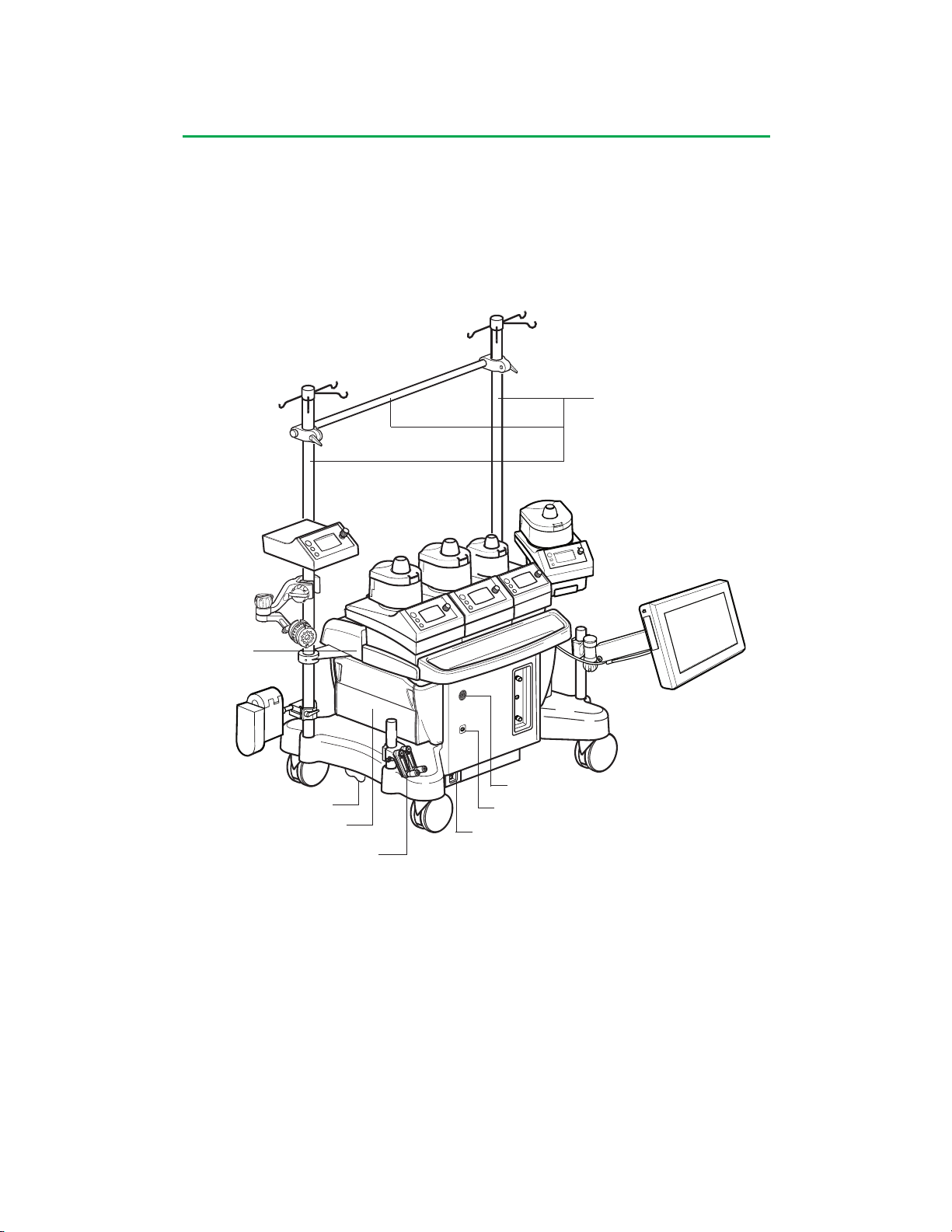
System Base
Vertical Poles and Crossbar
Cable
Cover
Module Cover
Wheel Lock
Hand Cranks
On/Off Switch
Power Status Indicator LED
Audio Output
The system base is a moveable platform designed for the flexible mounting of
system components on poles and on a central rail. The base houses the network
infrastructure that provides power and communications to all system components.
Each component connects to the system network via receptacles on the base. There
are 6 pump connections, 2 receptacles for the Central Control Monitor (CCM), 18
receptacles for modules, and 2 receptacles for a lamp. The base also provides 1 AC
outlet to supply power to auxiliary equipment.
AC (Mains)Power Switch
3-1
Page 41
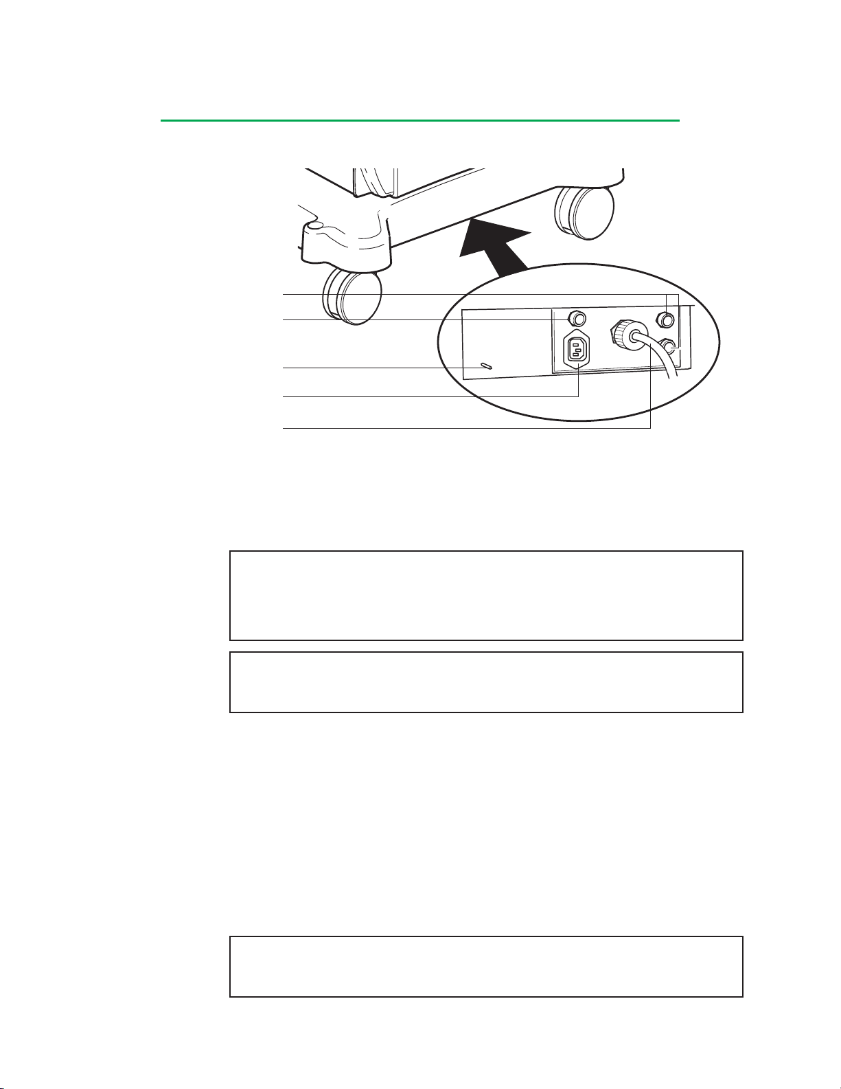
System Base
Base Components
Mains Power Circuit Breakers
Auxiliary Outlet Circuit Breaker
Ground Equalization Stud
Auxiliary Outlet
Mains Power Cord
Mains Power Cord
The AC (Mains) power cord connects the system to the wall electrical supply. When
the system is operating from the AC (Mains) power supply, the AC (Mains) power
status indicator LED located on the front panel is illuminated and steady.
Attach the system AC (Mains) power cord to an appropriate wall electrical supply as
indicated on the name plate label.
WARNING: Check the AC (Mains) power cord and plug for damage prior to use.
Do not use the system if damage to the power cord or plug is found. Damage
may include worn or twisted cord insulation and loose, bent, or missing plug pins.
Additionally, damage may result from tightly wrapping the power cord around any
HLM fixture or pole.
CAUTION: Do not use extension cords to connect the system to AC (Mains)
power or to connect modules or accessories to the system. Use of extension
cords may compromise performance.
In some countries, regulations require potential compensation; in this case, connect
the cable from the potential compensation network to the ground equalization stud.
Circuit Breakers
There are 3 resettable circuit breakers on the system base.
Two resettable circuit breakers located near the AC (Mains) power cord protect the
system from excessive power consumption. The breakers are protected from liquid
by a clear plastic cover.
The system will switch from AC (Mains) to Battery Power in the event that one
or both circuit breakers protecting the system trips. To reset the circuit breakers,
depress the push button(s) until it clicks into place. Verify that the system returns to
AC (Mains) power.
CAUTION: In the event that the breaker trips immediately after a reset, DO NOT
attempt to reset again. The system will only operate from battery power until it
has been repaired. Call for service.
One resettable circuit breaker protects the auxiliary outlet from excessive AC (Mains)
power draw.
3-2
Page 42
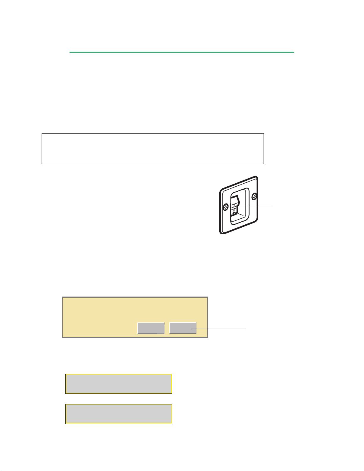
System Base
Please wait for the system to shut down. 10
Yes
Do you really want to shut down the system?
No
If the auxiliary outlet circuit breaker is tripped, devices plugged into this outlet will not
power ON. To reset the circuit breaker, depress the button until it clicks into place.
Auxiliary Outlet
The auxiliary outlet is an AC outlet protected with a 1.5 amp resettable circuit breaker
for the 100-120V system or a 0.7 amp resettable circuit breaker for the 220-240V
system.
Do not use this outlet to power devices or equipment which require voltage or current
above the specified limit.
CAUTION: The auxiliary outlet is not backed up by battery power. During loss
of AC (Mains) power, any equipment connected to the auxiliary outlet will lose
power and will remain unpowered until AC (Mains) power is restored.
Mains Power On and Off
The AC (Mains) power switch turns power to the system On or
Off and enables or disables the automatic battery backup.
When the system is operating from AC (Mains) power, the power
status indicator LED on the front panel is illuminated and steady.
To Turn the System On:
1. Press the top of the AC (Mains) power switch.
The system start-up tone sounds and indicates the audio system is working prop-
erly. If you do not hear the start-up tone, call for service.
To Turn the System Off:
Note: Failure to follow the controlled shut down procedure may result in improper
start-up at the next power-on.
1. Touch the Shut down button on the main screen.
A screen prompts the user to shut down the system.
User returns to main screen
2. Select Yes to shut down.
The shut down process takes approximately 10 seconds. A message will display
when it is safe to power down the system.
AC (Mains) Power Switch
(Switch Guard not shown)
It is safe to power down the system.
3. Turn the AC (Mains) power off by pressing the bottom of the AC (Mains) power
switch.
3-3
Page 43

System Base
System Power
The power system is located within the base and includes two internal DC power
supplies, integrated batteries, and an internal power manager. The power supplies
transform AC (Mains) power into the DC levels required by the system components.
The integrated batteries provide backup power in the event of AC (Mains) power loss
during use or when power needed exceeds power available.
The internal power manager monitors the power needed to run the system and
compares the power needed (load) with the power available (AC (Mains) power
capacity). If the power needed exceeds the power available, the system will switch to
battery power. The auxiliary outlet will remain powered as long as AC (Mains) power
is still available. To decrease the load, noncritical modules or pumps may be turned
off by the user. When the system power need falls below the available power limit for
at least 10 seconds, the system will automatically switch back to using AC (Mains)
power.
If the system switches to battery power, the battery alert tone will sound and the
power status indicator LED will flash. If a Perfusion Screen is open, a message
will be displayed on the CCM and posted in the Aux tab, the Power Source/Battery
Status icon will flash and display a color indicating approximate battery time available
and the approximate battery run time in minutes will be displayed above the Power
Source/Battery Status icon.
If the system switches to battery power, the battery alert tone will sound and the
power status indicator LED will flash. If the Main Screen is open, the Power Source/
Battery Status icon will flash and display a color indicating the approximate battery
time available and the approximate battery run time in minutes will be displayed
above the Power Source/Battery Status icon.
Note: If the system is started by battery power, the auxiliary outlet will not be
available. When AC (Mains) power is connected, the auxiliary outlet is immediately
powered and, after a short delay, the system will automatically switch to AC (Mains)
power.
Battery System
Integrated batteries provide uninterruptible battery backup power in the event AC
(Mains) power is lost or when power needed exceeds power available.
During power loss, fully charged batteries will power a fully loaded System 1 for at
least 60 minutes. A fully loaded System 1 is defined as:
A combination of 6 blood pumps, from the list below:
2 roller pumps, speed set to 120 RPM while using 1/2 in (12,7 mm) I.D. x 3/32 in
(2,4 mm) wall tubing and/or speed set to 190 RPM while using 3/8 in (9,5 mm)
I.D. x 3/32 in (2,4 mm) wall tubing, properly occluded and fluid temperature of
25°C;
2 roller pumps, speed set to 100 RPM while using 1/4 in (6,4 mm) I.D. x 3/32 in
(2,4 mm) wall tubing, properly occluded and fluid temperature of 25°C;
1 roller pump, speed set to 50 RPM while using 1/4 in (6,4 mm) I.D. x 3/32 in
(2,4 mm) wall tubing, properly occluded and fluid temperature of 25°C;
1 roller pump, speed set to 30 RPM while using 8:1 dual tubing set, properly
occluded and fluid temperature of 5°C;
1 centrifugal pump, flow set to 5.0 L/min, a backpressure of 400 mmHg and fluid
temperature of 25°C;
3-4
Page 44

System Base
18 monitoring modules; any combination of flow, temperature, pressure, level,
occluder, air bubble detect, and serial interface modules; all modules assigned and
activated;
1 Electronic Gas Blender module, connected and activated;
1 lamp; connected and activated;
1 Central Control Monitor; connected and activated.
WARNING: If a partially charged battery system is used, there may be less than
60 minutes of battery power available for a fully loaded system.
WARNING: Turn the system power off at the AC (Mains) power switch on the
system before inspection, cleaning, preparation for use, or storage in order to
turn off both the battery power and the AC (Mains) power.
WARNING: Charge the batteries monthly. Storage of a System 1 without charging the batteries monthly may damage the batteries and lead to overstated battery life. This damage, caused by a gradual discharge of the batteries, may cause
loss of battery backup without warning.
Battery charge level should be checked before each case.
The batteries must be fully recharged after storage, prior to use on a case. During storage there is a gradual discharge of the batteries which may reduce the available battery
backup time. A power status indicator LED on the front panel of the base indicates the
status of the battery charge. When starting a system that has been in storage, allow at
least 1 minute to elapse after the CCM displays the Main Screen, before checking the
power status indicator LED.
On the Main Screen, the Power Source/Battery Status icon will display a color indicating
the approximate battery time available. In addition, charge level information can be found
within a Perfusion Screen. The Power Source/Battery Status icon will display a color indicating the approximate battery time available. More information is available in the Power
subtab when a Perfusion Screen is open.
The batteries will charge, as needed, while the system is operating from AC (Mains)
power.
To recharge the batteries, the system must be plugged into the AC (Mains) power supply
with the AC (Mains) power switch turned on. It takes up to 13 hours to fully recharge the
batteries.
As the batteries recharge, the color of the power status indicator LED and Power Source/
Battery Status icon will change to indicate the condition of the batteries:
• Steady green indicates a battery system with one hour or more run time for a fully
loaded system;
• Steady red indicates a battery system with less than one hour run time for a fully
loaded system.
3-5
Page 45
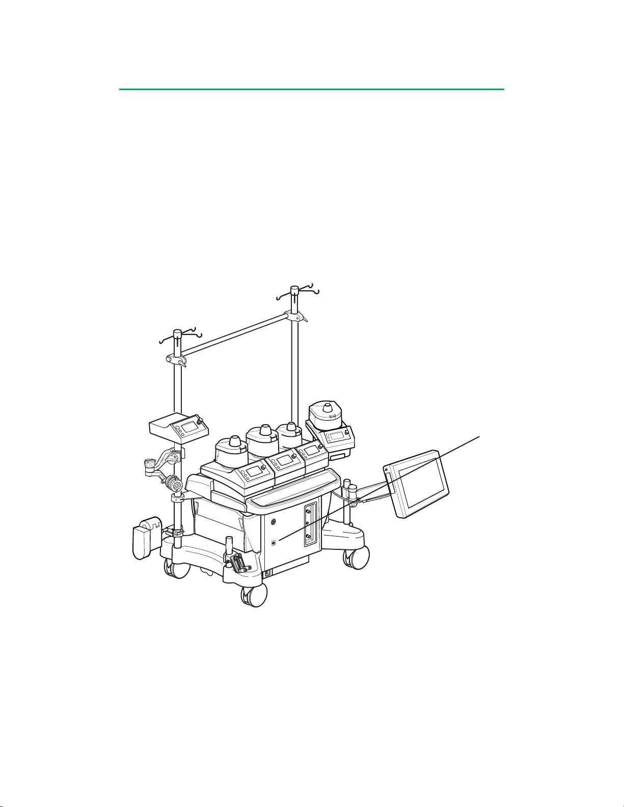
System Base
When the system is operating from battery power, an audible battery alert tone
sounds and repeats every 3 minutes. The battery alert tone is a unique, single tone
pattern used only to indicate that the system is operating on battery power. The battery alert tone cannot be muted. In addition, the Power Source/Battery Status icon
flashes and the power status indicator LED on the front panel flashes. If a Perfusion
Screen is opened, a message is displayed in the message area of the CCM and in
the Messages subtab in the Aux tab.
There are three different indicators that provide information regarding battery status:
the Power Status Indicator LED, the Central Control Monitor Power Source/Battery
Status Icon, and the Power subtab within the System tab.
Power Status Indicator LED – Provides a status as the batteries charge or the battery capacity if the battery system is actively providing backup power. When starting
a system that has been in storage, allow at least 1 minute to elapse after the CCM
displays the Main Screen, before checking the power status indicator LED.
Power Status Indicator LED
The Power Status LED provides information about battery life as follows:
When operating from AC (Mains) power:
• Steady green indicates a battery system with greater than one hour run time
with a fully loaded system.
• Steady red indicates a battery system with less than one hour run time with a
fully loaded system.
When operating from the battery system:
• Flashing green indicates 30 minutes or more battery life at present discharge rate
• Flashing yellow indicates 15 minutes or more, but less than 30 minutes battery life
at present discharge rate
• Flashing red indicates less than 15 minutes battery life at present discharge rate.
3-6
Page 46
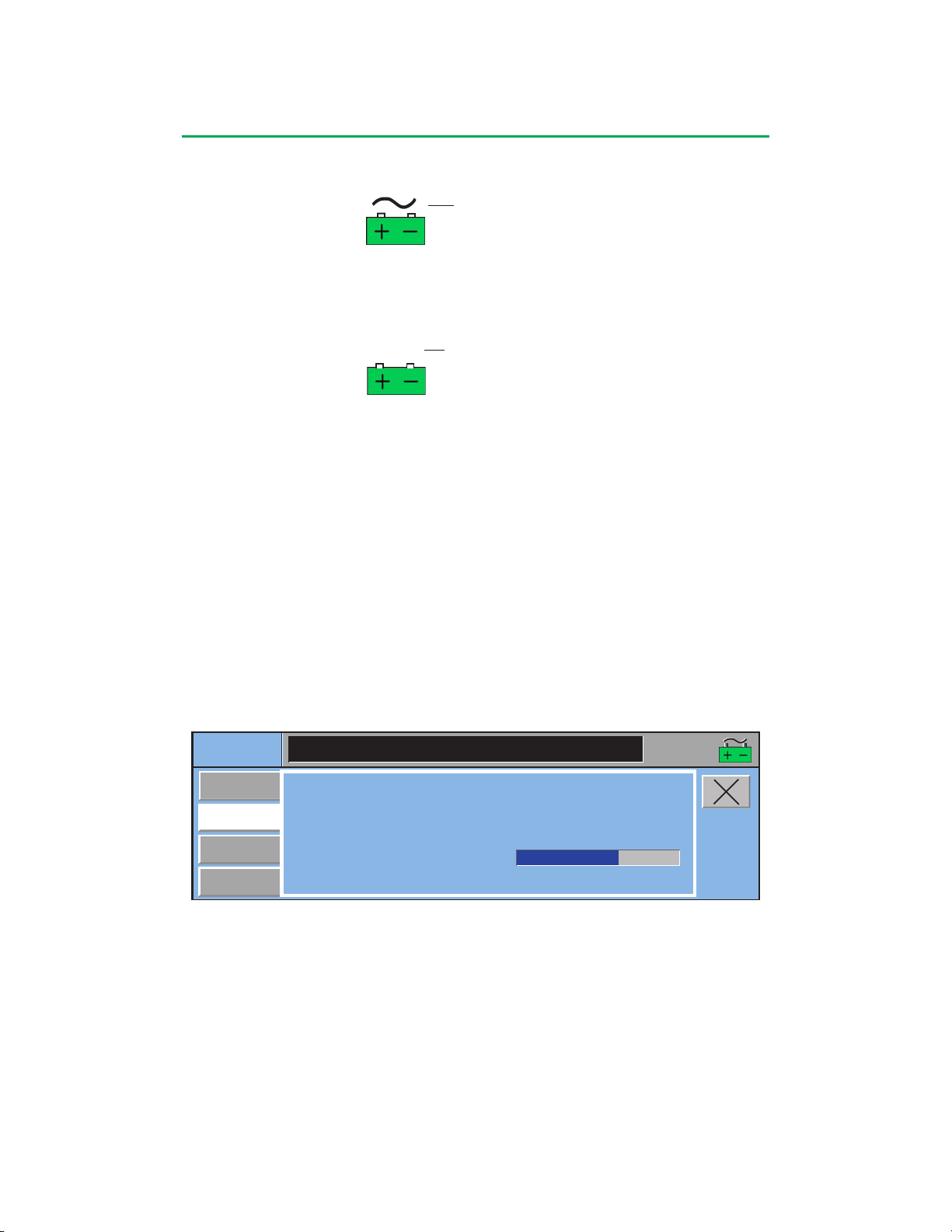
System Base
53 min
53 min
Central Control Monitor Power Source/Battery Status Icon (only displayed on the
Main and Perfusion Screens) – Provides information about battery life as follows:
AC (Mains) Power
When operating from AC (Mains) Power:
• Steady green indicates a battery system with greater than one hour run time
with a fully loaded system
• Steady red indicates a battery system with less than one hour run time with a
fully loaded system
On Battery Indicator
When operating from the battery system:
• The approximate battery life in minutes is displayed above the Power Source/Battery
Status icon
• The color of the Power Source/Battery Status icon will change as the estimated
remaining capacity in minutes decreases:
• Flashing green indicates 30 minutes or more battery life at present discharge rate
• Flashing yellow indicates 15 minutes or more, but less than 30 minutes battery life
at present discharge rate
• Flashing red indicates less than 15 minutes battery life at present discharge rate.
Indicator
The time displayed above the Power Source/Battery Status icon, the color of the
icon, and the available capacity in minutes in the Power subtab within the System tab
should only be used as approximations of the amount of time remaining.
Power subtab within the System tab (only displayed on the Perfusion Screen) Contains a summary of the power information for the system. See the
Central Control Monitor section, Power Subtab for further details.
System
Settings
Power
Reassign
Module
Module Info
Power Source: AC Power
AC Power Capacity Used: 11.8 %
Estimated Battery Time Remaining (min): 82
Battery Charge Level:
16:07:51
The Battery Charge Level found in the Power subtab within the System tab provides
a bar graph indicating the approximate charge status of the battery.
• Power Source - AC power or battery.
• AC Power Capacity Used - Indicator of power consumption when using AC power.
• Estimated Battery Time Remaining - Provides an estimated remaining battery
backup time, regardless of current Power Source.
Note: This will be the same time estimate as shown over the Power Source/Battery Status icon when on battery backup.
• Battery Charge Level - Provides a bar graph indicating the charge status of the
battery.
In summary, if the system is operating from batteries, the Power Status Indicator
LED will flash. If the system is operating from batteries and if a Perfusion Screen is
opened, a message is displayed in the message area of the CCM and in the Messages
3-7
Page 47
System Base
subtab within the Aux tab, and an estimated battery time available appears above the
Power Source/Battery Status icon.
WARNING: Failure to properly charge and maintain the System 1 Base
Batteries can cause the unexpected loss of battery backup function.
WARNING: The Battery Charge Level bar graph and power status indicators
depend on the proper charging and maintenance of the battery system. Failure
to properly charge and maintain the System 1 battery system can cause
battery failures.
CAUTION: Replace the batteries every 2 years, OR whenever the batteries
cannot be fully recharged within 13 hours, OR whenever fully charged batteries
will not power a fully loaded system for 60 minutes.
CAUTION: Do not store batteries in a discharged state as this will damage
them.
Decreasing the power consumption of the system while operating on battery power
can enable the batteries to power the system for more than 1 hour. Turning off noncritical devices will decrease the power needs of the system.
If the system shuts down due to depletion of battery power, make sure to plug the
system into available wall power and that the system power switch is ON.
Battery System Testing
The batteries are tested at different times during use of the system.
Automatic Testing of Switching to Battery System
Each time the system is powered on, a switching test of the battery system is performed. If the system detects an issue with battery system circuitry at start-up, the
following message will be displayed: “Battery Cannot be Charged - Full Backup May
Not be Available”.
If this message is posted, contact Terumo Customer Service. Do not attempt to operate the system until it has been serviced.
In addition, battery circuit components are monitored constantly during operation. If
a problem is detected, the following message will be displayed: “Battery Cannot be
Charged - Full Backup May Not be Available”.
If this message is posted, contact Terumo Customer Service. Do not attempt to operate the system until it has been serviced.
Manual Testing of Switching to Battery System
To test the battery switching function, unplug the system when it is turned on. If the
system does not immediately switch to battery power, contact Terumo Customer Service. Do not attempt to operate the system until it has been serviced.
3-8
Page 48
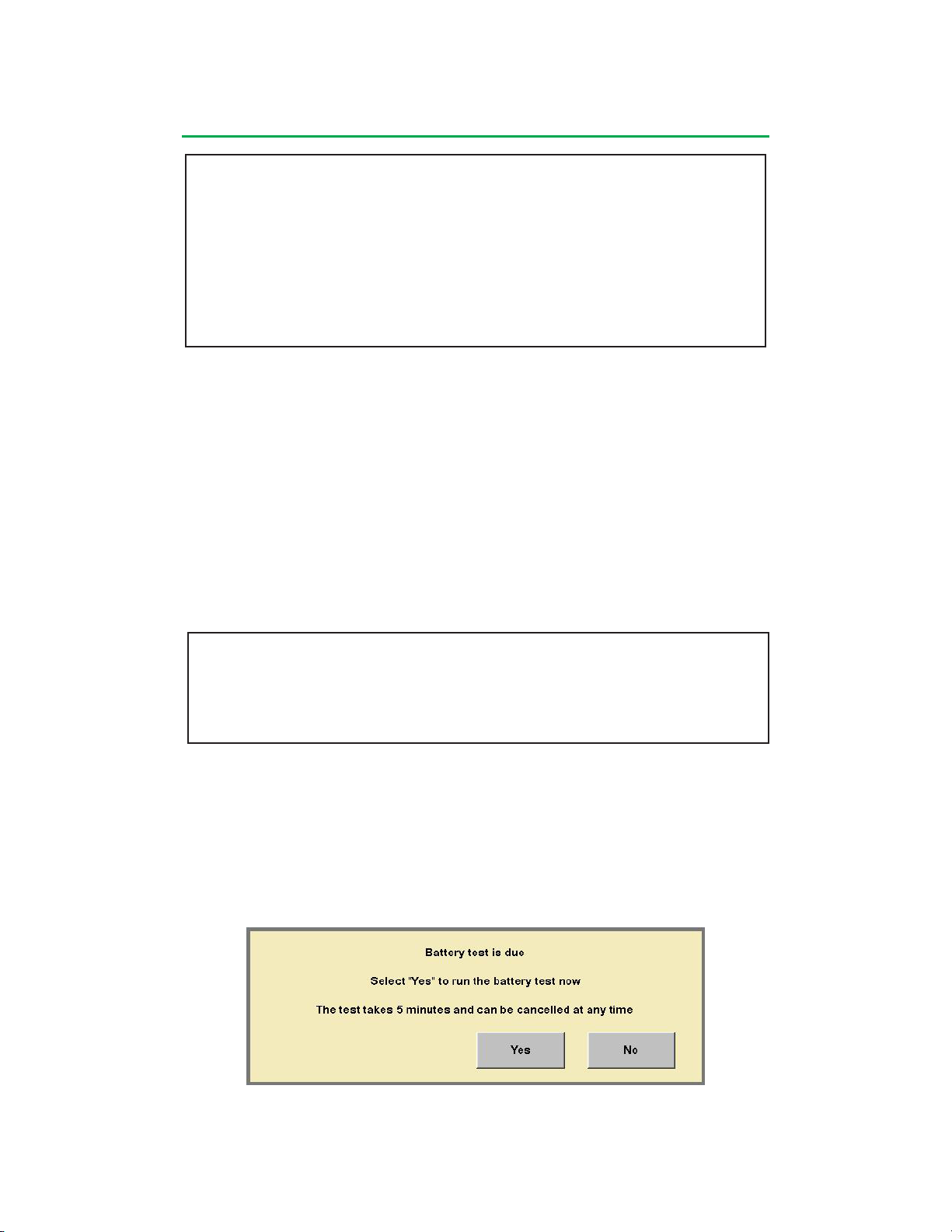
System Base
WARNING: The following behavior while operating on Battery power indicates
discharged or damaged batteries:
• Battery Time Remaining decreases faster than elapsed time on
battery
• Power Source/Battery Status Icon changes color faster than elapsed
time on battery
• Red Power Source/Battery Status Icon after the system is returned
to AC (Mains) Power.
Battery Capacity Updates (Battery Test)
Whenever the system is operating on battery power, it will update its estimate of
battery capacity.
Watch for battery capacity updates whenever the system is operating on battery
power.
If the Battery Test indicates a damaged or discharged battery AND the system may
not be fully charged, recharge the batteries and then repeat Battery Capacity Test.
To fully recharge the batteries, the system must be plugged into the AC power supply
with the AC (Mains) Power switch turned On. It takes up to 13 hours to fully recharge
the batteries. If the Battery Test indicates a damaged or discharged batteries AND
the System should be fully charged, call Terumo Customer Service. Do not use the
system until the battery system has been serviced.
WARNING: If the Battery Capacity Updates indicate less than 60 minutes battery
power AND the battery system should be fully charged, call Terumo Customer
Service. Do not use the system until the battery system has been serviced.
Battery Test Reminder
Every 60 days, if the system has not been run on battery for at least 5 minutes, the
system will post a reminder at the Main Screen to perform a Battery Test. The most
accurate estimate is achieved after 5 minutes operation without AC (Mains) Power.
The Battery Test may be skipped or canceled at any time, but the reminder will return
whenever the Main Screen is entered until the Battery Test is completed.
The Battery Test reminder appears in a message box as follows:
Select “No” to return to the Main Screen
Selecting “Yes” will display the following message box:
3-9
Page 49
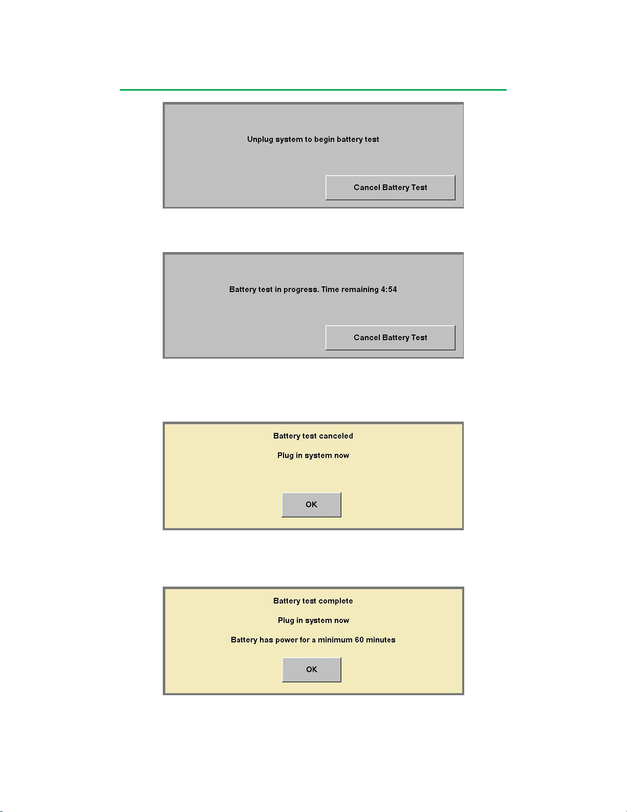
System Base
To return to the Main Screen, select “Cancel Battery Test”
Unplugging the system will display the following message box:
The system will count down to zero from five minutes to complete the Battery Test.
To cancel the test, select “Cancel Battery Test” (or plug the system back in).
If the Battery Test is canceled without plugging the system back in to AC (Mains)
Power, the following message box will be displayed:
Plugging in the system will remove the message box, canceling the Battery Test.
Selecting “OK” will remove the message box canceling the Battery Test.
One of the following message boxes will display upon completion of the Battery Test:
The above message box will be displayed if the battery system has one hour or more
capacity for a fully loaded system
3-10
Page 50
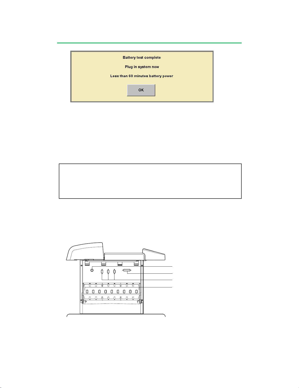
System Base
The above message box will be displayed if the battery system has less than one
hour capacity for a fully loaded system
If the Battery Test indicates the batteries have less than one hour capacity AND
the system may not be fully charged, recharge the battery and then repeat the
Battery Test. To fully recharge the battery, the system must be plugged into the
AC (Mains) Power with the AC (Mains) Power Switch turned on. It takes up to 13
hours to fully recharge the batteries, if battery charge is very low.
WARNING: If the Battery Capacity Updates indicate less than 60 minutes
battery power AND the system should be fully charged, call Terumo Customer
Service. Do not use the system until the battery system has been serviced.
System Network
The network design allows the different types of system modules and pumps to
be connected to any dedicated receptacle on the base. It also allows multiple
types of modules to be connected to the system. The user can define how these
modules interact with the system and each other and can set alert and alarm
responses and monitoring limits via the Central Control Monitor.
Lamp Receptacle
CCM Receptacle
Pump Receptacles
Module Receptacles
There are 9 module receptacles, 3 pump receptacles, a Central Control Monitor
receptacle and a lamp receptacle on each side. If necessary, a pump can be
plugged into a module receptacle.
3-11
Page 51
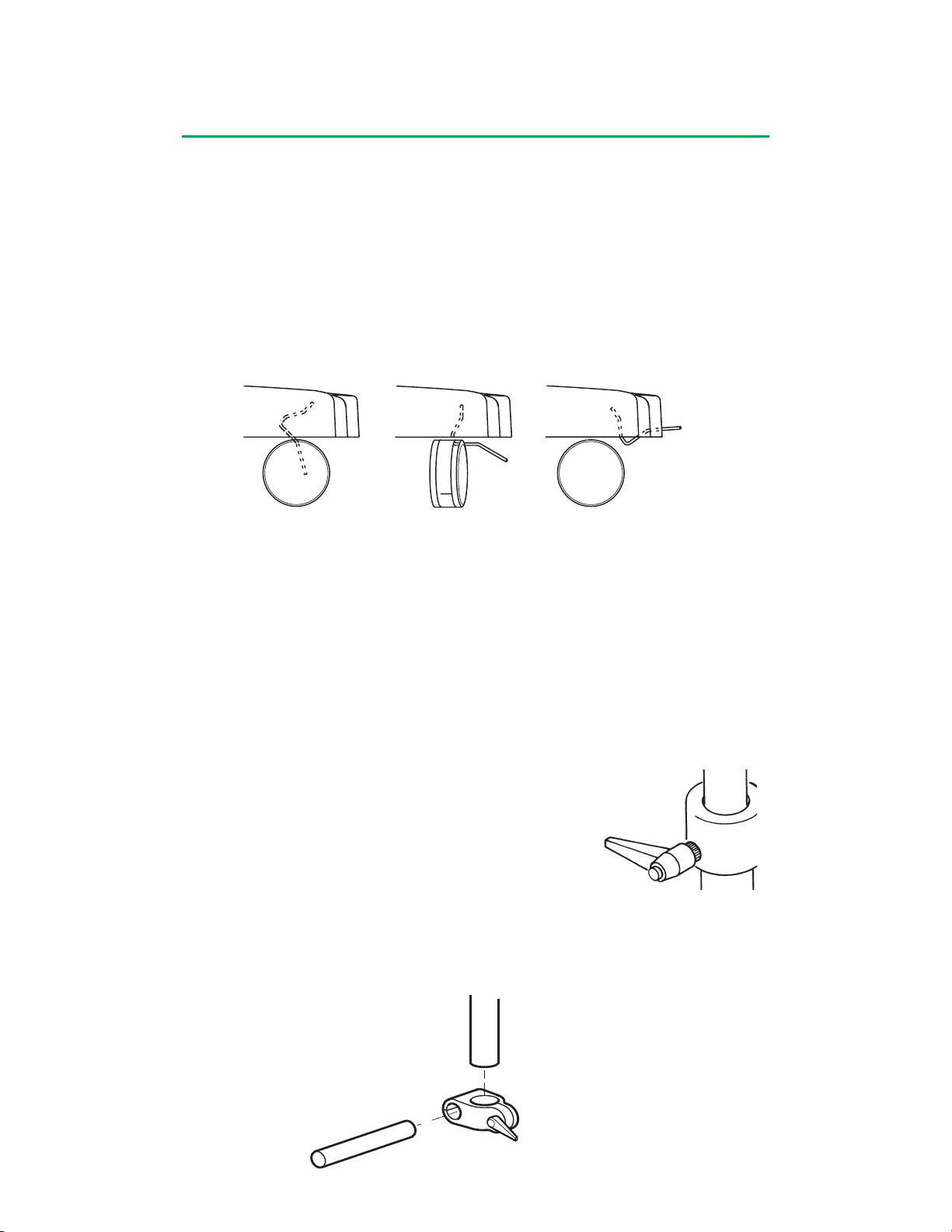
System Base
Standoffs are provided in the accessories kit. Two standoffs should be installed on a
module receptacle to securely fasten a pump cable or flowmeter cable to the module
receptacle. Modules cannot be inserted into a module receptacle when standoffs are
installed.
Casters and Wheel Lock System
The base is mounted on four casters. Each side of the base has a pair of casters
and a locking lever that can be set in three positions to either lock the wheels of the
casters to prevent unintended movement of the base, allow free movement of the
casters and wheels, or lock the casters to allow the base to roll while maintaining a
fixed position of the wheels.
Position 1 Position 2 Position 3
Apply upward or downward pressure on the locking lever to change the position.
Position 1
The casters are locked in place and will not move. When the system is in use, the
wheel lock should be set in the locked position.
Position 2
The casters are unlocked and move in all directions.
Position 3
The casters align parallel to the base and allow side-to-side movement only.
Poles, Shelf, and Brackets
There are two 1.30 in. (3,3 cm) diameter, stainless steel
vertical telescoping poles attached to the base platform
for mounting devices to the system.
Extend the inner section of the telescoping pole by
adjusting the handle screw on the collar of the pole. Do
not extend beyond a maximum of 18 in. (45,7 cm) from
the retracted position.
Special fittings connect a horizontal cross bar to the two vertical poles.
3-12
Page 52
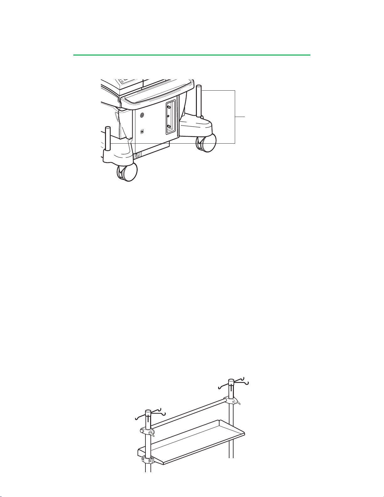
System Base
There are two additional shorter vertical poles, one on either side of the front of the
base.
Short Vertical Poles
The optional System 1 Shelf mounts between the 2 vertical telescoping poles. The
shelf provides storage space for items up to a maximum of 50 pounds (22,6 kg).
Make sure that the shelf is positioned such that it does not interfere with access to
the pumps or other devices. Ensure that all pumps can be hand-cranked without
interference from the shelf.
Do not mount, or otherwise attach, any devices or accessories to the shelf. The
shelf is for storage of lightweight items only.
Do not allow stored items to extend beyond the edge of the shelf.
To mount the shelf to the base:
Loosen the handle screws on the collars of both of the poles. Remove the inner
section of the telescoping pole. Remove both of the collars. If the desired position of
the shelf is below the horizontal crossbar, loosen the handle screws on both of the
crossbar fittings. Remove the crossbar and fitting by sliding up off the poles. Use a
3/16 in. ball driver (provided with Accessory Kit) to loosen the end caps of the shelf.
Position the shelf between the poles by lowering it from the top of the poles to the
desired height. Make sure the shelf is level. Tighten the shelf end caps using the 3/16
in. ball driver. Reinstall crossbar (if removed) and tighten handle screws. Reinstall
the collars taking care that the handle screws extend through the holes at the top
of the vertical poles. Reinsert the inner section of the telescoping pole using the
collar handle screws to adjust the desired height. Make sure all fittings are tight and
secure.
3-13
Page 53

System Base
The instrument tray in front of the pump platform provides storage space for items up
to a maximum of 10 pounds (4,5 kg).
There are dedicated brackets for many of the components used with the Terumo®
Advanced Perfusion System 1. Refer to specific chapters for instructions on how
to attach pole mount brackets for: roller pumps, centrifugal control units, flowmeter
modules, occluder head, and the Central Control Monitor (CCM).
Loading Zones
To prevent tipping, only transport the system in the lengthwise direction. Do not
transport the system up or down an incline greater than 10 degrees. Do not hang
more than 10 lbs. (4,5 kg) total from the hooks on each telescoping pole. A minimum
of two roller pumps must be placed on the system base pump platform. Distribute the
weight of additional system components and accessories according to the following
figures and instructions.
The System 1 Base includes four poles for mounting equipment and a pole-mounted shelf for
holding loose items. When mounting equipment, it is important not to overload the system or
to concentrate the weight where it could cause the system to tip. The mounting area is divided
into six zones, with limits on the amount of that weight can be mounted in each zone. The
table below shows the limits for each zone.
The drawings below show the location of each zone. Some of the zones overlap (e.g., zones A
and E). If you mount equipment in the overlap area, its weight counts against the limits for both
zones (i.e., it is double counted). To help you calculate the loads, the table after the drawings
shows the weight of various pieces of equipment.
Some points to keep in mind:
• For stability, place at least two roller pumps on the base
• For calculating load, the center of the weight of the equipment determines which zone it is
in, regardless of which pole the equipment is mounted on
• Area D is for the CCM only
• The load in Area C includes both equipment mounted in the area and the weight of
anything placed on the shelf. The weight of the shelf is not included.
• The weight of fluids contained in the equipment (e.g., a reservoir) must be included in the
load calculations
Zone Weight
A 90 lbs. 40,8 kg
B 90 lbs. 40,8 kg
C 50 lbs. 22,7 kg
D CCM and Mounting Arm
E 90 lbs. 40,8 kg
F 90 lbs. 40,8 kg
Note: The dimensions noted in the following graphics refer to inches and (meters).
3-14
Page 54
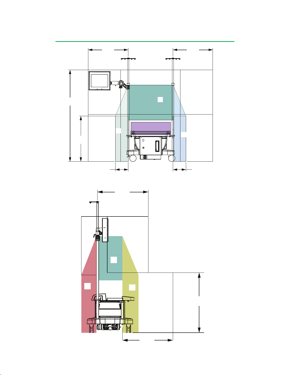
System Base
29.5 in.
29.5 In.
(0,75 m)
(0.75 m)
67.5 in.
67.5 In.
(1,71 m)
(1.71 m)
29.5 In.
29.5 in.
(0,75 m)
(0.75 m)
D
C
33.5 in.
33.5 In.
(0,85 m)
(0.85 m)
A
2 PUMPS MINIMUM
B
9.5 in.
9.5 In.
(0,24 m)
(0.24 m)
(0,24 m)
(0.24 m)
Front View of System Showing Loading Zones
29.5 In.
29.5 in.
(0.75 m)
(0,75 m)
D
C
9.5 in.
9.5 In.
E
F
29.5 In.
29.5 in.
(0.75 m)
(0,75 m)
Side View of System Showing Loading Zone
3-15
34.9 in.
34.9 In.
(0,89 m)
(0.89 m)
Page 55
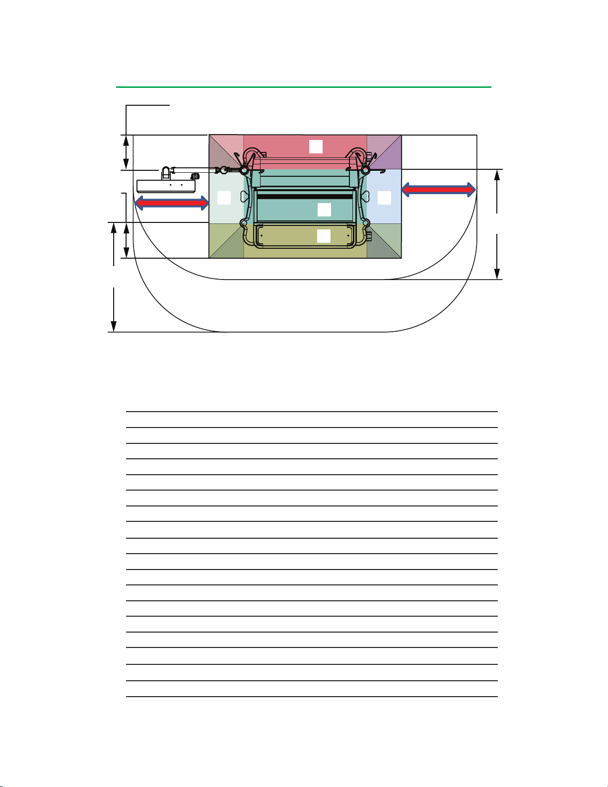
System Base
9.5 in.
9.5 In.
(0,24 m)
(0.24 m)
E
9.5 in.
9.5 In.
(0,24 m)
(0.24 m)
29.5 In.
29.5 in.
(0.75 m)
(0,75 m)
Transport Direction
Transport Direction
A B
C
D
F
Top View of System Showing Loading Zones
Weights of various system components are given in the table below.
Component Weight
Central Control Monitor and mounting arm 26 lbs. (11,8 kg)
Roller Pump, 4 in. 23.5 lbs. (10,7 kg)
Roller Pump, 6 in. 28.5 lbs. (12,9 kg)
Centrifugal Control Unit 2.4 lbs. (1,1 kg)
Centrifugal Drive Motor 3.2 lbs. (1,5 kg)
Manual Drive Unit 5.1 lbs. (2,3 kg)
Lamp, 33 inch (83,8 cm) 3.1 lbs. (1,4 kg)
Lamp, 15 inch (38,1 cm) 2.2 lbs. (1 kg)
Occluder head 4.2 lbs. (1,9 kg)
Air Sensor 0.48 lbs. (0,22 kg)
Flowmeter Module 1 lb. (0,5 kg)
Roller Pump Pole Mount 3.6 lbs. (1,6 kg)
Dual Pumps Pole Mount 5.7 lbs. (2,6 kg)
Descending Pump Bracket 5.5 lbs. (2,5 kg)
Centrifugal Unit Pole Mount 1.4 lbs. (0,6 kg)
Shelf 7 lbs. (3,2 kg)
Flexible Mounting Arm 3.5 lbs. (1,6 kg)
Flowmeter Mounting Bracket 0.6 lbs. (0,27 kg)
Hand Crank Bracket and two Hand Cranks 1.7 lbs. (0,8 kg)
29.5 in.
29.5 In.
(0,75 m)
(0.75 m)
3-16
Page 56
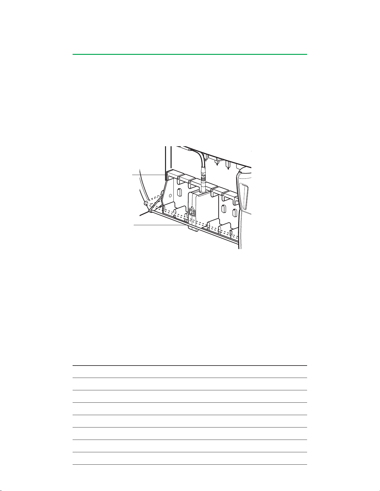
System Base
Module Bracket System
Each module receptacle is surrounded by a rectangular shaped bracket that is
mounted on the side of the base. This bracket, along with a crossbar, holds the
modules in place.
To Insert or Remove Module:
1. Pull crossbar down.
2. Insert or remove module
from receptacle.
3. Release crossbar
Bracket
Crossbar
Pump Platform
The pump platform is designed to provide adaptable mounting combinations of roller
pumps onto the system base. The platform consists of a rail, adjustable endcaps,
and extensions that are used in conjunction with the endcaps.
The chart below represents the placement of roller pumps on the platform.
L indicates a large roller pump, S indicates a small roller pump. Other roller pump
combinations require the use of a pole mount bracket.
Based on the chart, determine the size extension that is required for the pump
combination to be used. Extensions are located in the accessories kit.
No Extension Small Extension Large Extension
L S S S S S L S S L L
S S L L S S S S L S L
L S L L S S L L S L S
S L S S S L S L L S S
S L L S L S S L S L L
L L S S S S S L L S L
L L L S L L S
S S S
3-17
Page 57
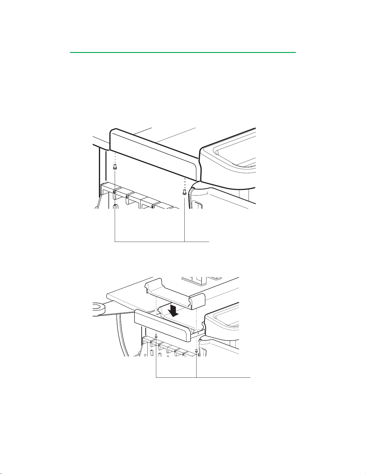
System Base
To Install or Remove Extensions:
1. Remove cable cover.
2. Remove pumps.
3. Remove module cover.
4. Loosen set screws on each side of the base. Some modules may need to be
removed to access the set screws.
5. Slide endcaps out.
Set Screws
6. Insert or remove the extension.
• If removing extensions, remove securing screws and remove extension.
• If adding extension, insert extension and install securing screws.
Securing Screws
7. Push the end caps in until they stop.
8. Tighten set screws. Set screws must be securely tightened to ensure pump
stability during operation.
9. Install pumps according to the instructions in Roller Pump chapter.
10. Install module covers and cable cover according to the instructions at the end of
this chapter.
3-18
Page 58
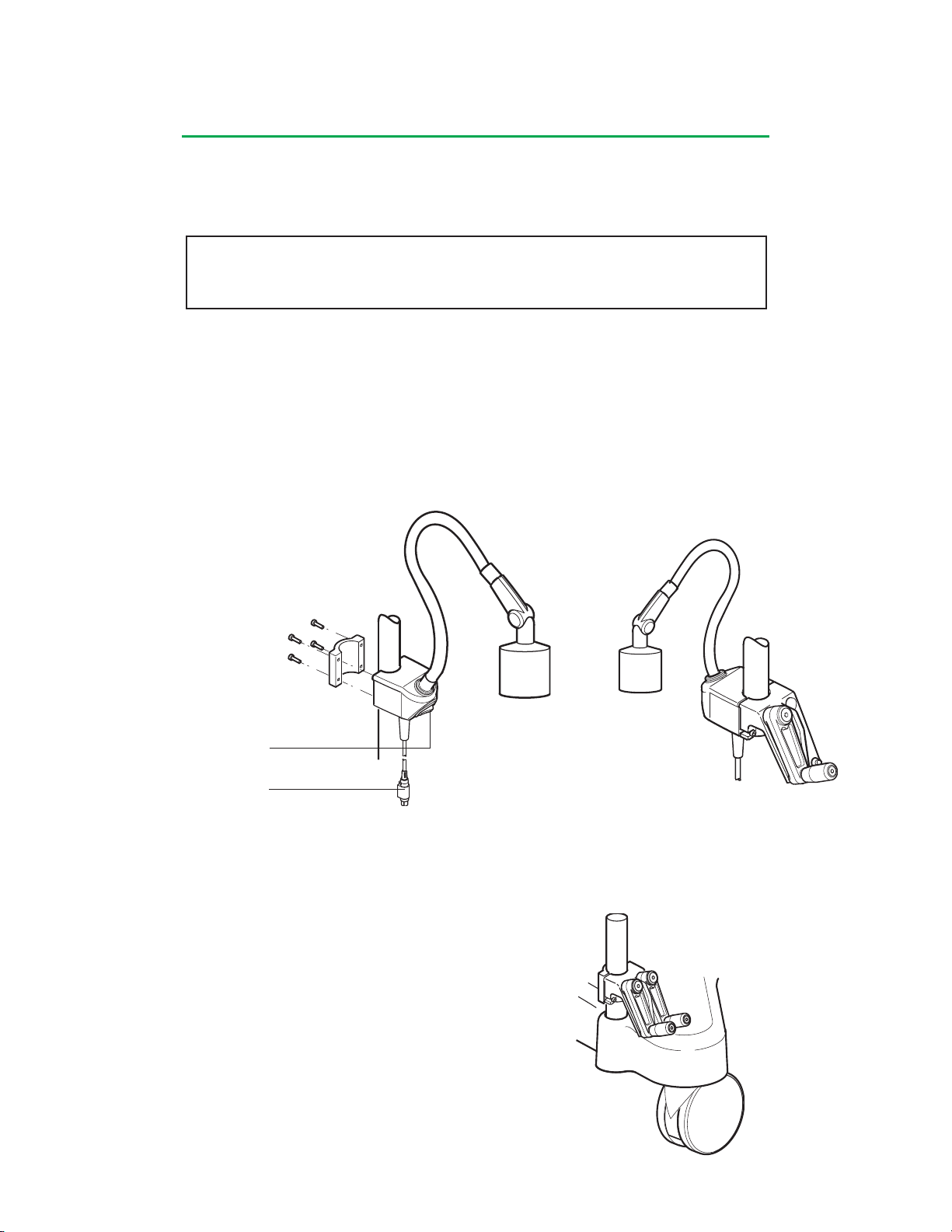
System Base
Lamp
The system lamp is an optional item. The lamp mounts to any of the system poles. It
connects to the system base for power and uses a 20 watt, 24 volt halogen bulb. The
lamp has a flexible shaft for easy positioning.
CAUTION: The lamp may get hot when powered on for extended durations. Do
not allow the lamp housing to touch the patient, user, perfusion circuit or other
equipment
To Mount a Lamp to the System Base:
1. Mount lamp bracket to pole.
2. Plug lamp into base receptacle.
3. Turn lamp On.
4. Position as needed.
The front portion of the lamp bracket and the front portion of the hand crank bracket
can be coupled into one system to reduce the number of brackets attached to the
poles.
On Switch
To base connector
Hand Cranks
Hand cranks should be positioned for easy access during emergency conditions.
To Mount the Hand Cranks to a Pole:
1. Mount hand crank bracket to pole.
2. Place hand cranks in the bracket slots.
3-19
Page 59
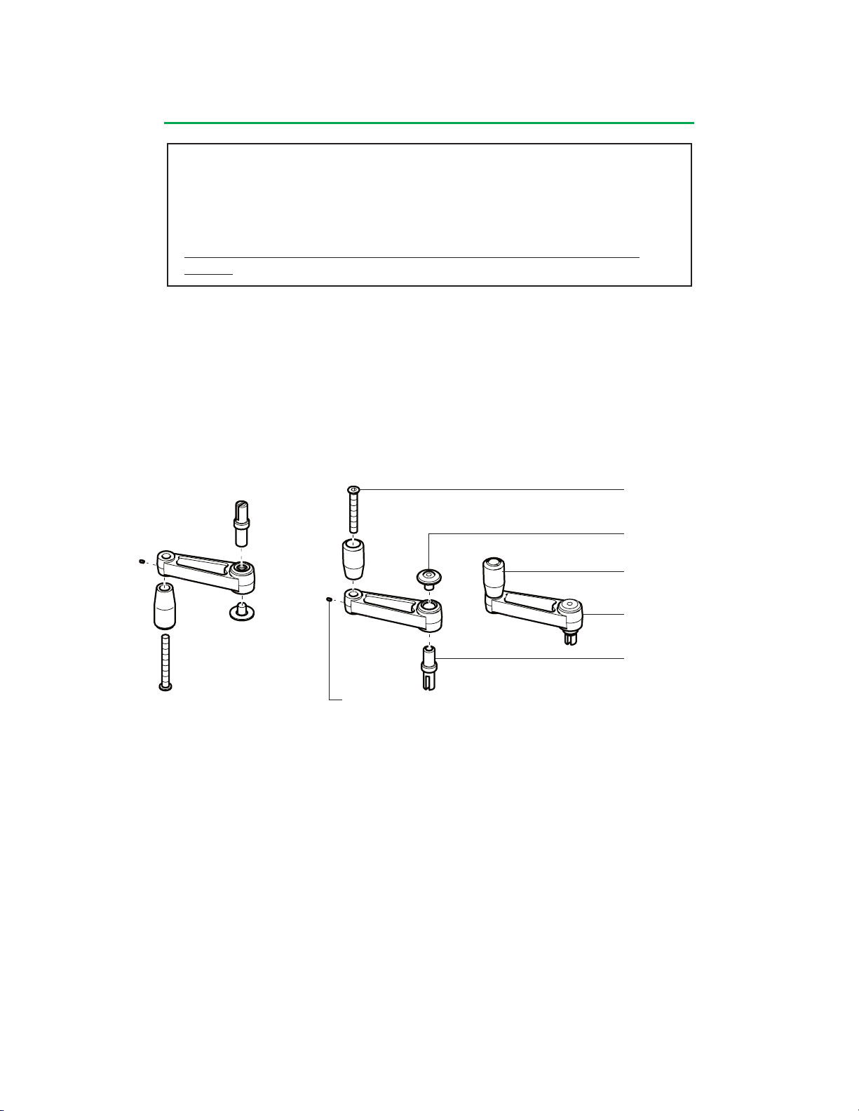
System Base
WARNING: Hand cranks must be properly setup to allow hand cranking in the
same direction as that selected for forward flow for the roller pump.
WARNING: All roller pumps used in a hospital must be set to run in the same
default direction for forward flow to prevent unintended retrograde pumping.
RETROGRADE PUMPING MAY CAUSE SEVERE PATIENT INJURY OR
DEATH.
To Change Hand Crank Direction:
1. Remove screw and cap from the hand crank arm.
2. Remove shaft from the hand crank arm by sliding the shaft out of the bearing.
3. Insert the shaft into the bearing on the opposite side of the hand crank arm.
4. Reinstall the cap and screw and tighten screw.
5. Loosen the setscrew and remove the handle screw and remove the handle.
6. Insert handle into opposite side of hand crank and tighten setscrew and handle
screw.
Handle Screw
Cap and Screw
Handle
Hand Crank Arm
Shaft
Set Screw
Test Before Use
Test hand crank to ensure it rotates the pump rollers in the direction of forward flow.
If the pump is difficult to turn, unplug the pump cable either at the system connection
or at the pump. Reconnect the cable after test. Verify that the hand crank turns freely
without moving the pump rollers when it is rotated in the opposite direction of forward
flow.
Ensure that the hand crank can be used properly without interference from pole
mounted pumps.
Cable Management
The base provides a cable management system that uses a series of cable clips
attached to the pump platform and cable management tray.
There are 3 clips on each side of the base and 5 clips on the back of the system.
To Arrange Cables:
1. Push the cable into individual clips and route cable toward the cable access area
of the module cover.
3-20
Page 60
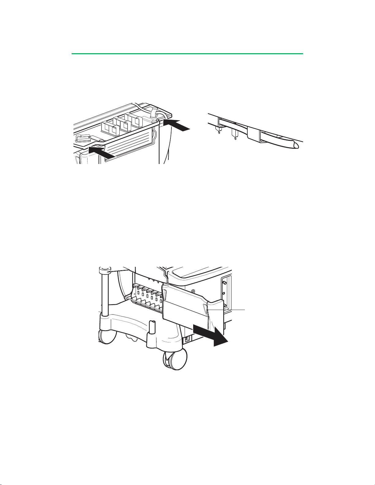
System Base
2. For pump cables, route cable through the clips and attach to the pump.
3. For modules, the cable exits at the access area. Route to the appropriate
location.
4. Install module and cable covers.
Access Area
Access Area
Module Covers
The module covers are located on each side of the base and provide protection from
liquid spills. Users may view modules through the cover if required.
To Remove Module Cover:
1. Grasp the module cover handle.
2. Pull toward the front of the base.
To Replace Module Cover:
1. Align the cover on the slide rail.
2. Push into place.
Handle
Cable Cover
The cable cover is mounted on the back of the system base and provides protection
from spills.
To Install Cover:
1. Slide front part of cover under roller pumps on the base.
2. Align the latches with the holes in the pole retaining brackets and insert the
latches through the holes.
3. Push the latch lever down to close each latch and secure the cable cover to the
base.
3-21
Page 61
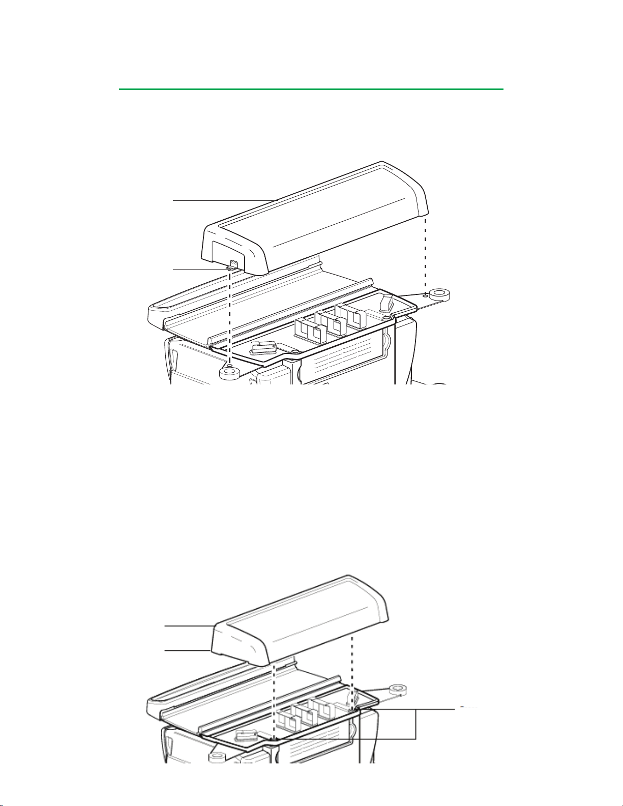
System Base
To Remove Cover:
1. Pull up the latch lever to open each latch.
2. Lift the cover off the base and out from under the roller pumps.
Front
Latch
Cable Cover (for the Terumo® Advanced Perfusion System 1, 801763 and 801764,
with serial numbers less than 1000)
To Install Cover:
1. Slide front part of cover under roller pumps on the base.
2. Place cover over rear cable management tray.
3. Apply pressure to the outer edges of the front of the tray until tabs snap into
place over the cable management tray.
4. Apply pressure to the rear of the tray to lock the cable cover into the snaps.
To Remove Cover:
1. Grasp the outer edges of the side of the cover firmly and lift.
Front
Tabs
Snaps
3-22
Page 62
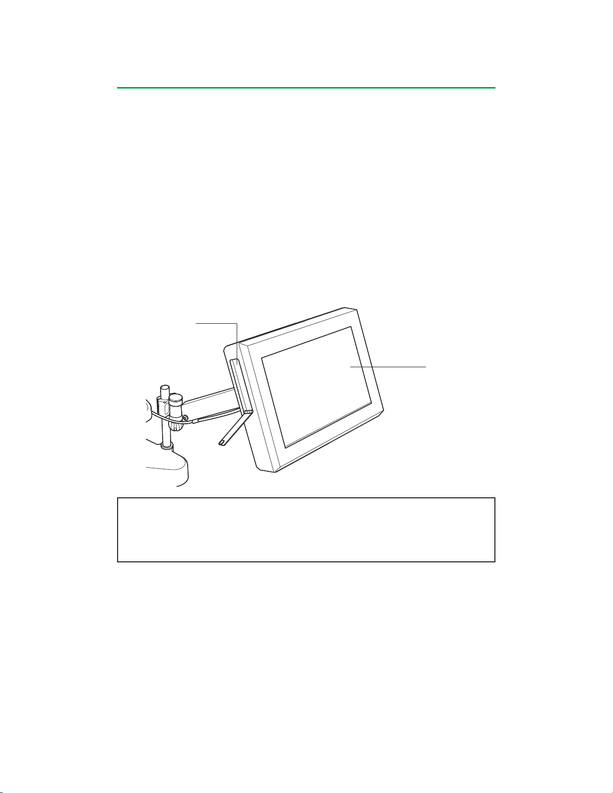
Central Control Monitor
Features
The Central Control Monitor (CCM) combines an embedded computer, a touch
screen, and a graphical user interface (GUI) to provide a centralized display of
system information and on-screen control of all system devices. The CCM is used
to create perfusion screens including selecting the number and types of devices
and sensors, selecting device names and colors, assigning Perfusion Screen
representations to physical modules, connecting devices to safety systems, and
selecting alert and alarm limits and device responses. During use, the CCM monitors
the system for alert, alarm, error, or status messages and displays the highest priority
message in a dedicated message area. The CCM also allows the user to initiate
automatic control functionality such as Pulse mode flow, servo regulation to pressure
and flow, and automatic cardioplegia time or volume delivery.
A cover protects the CCM when the system is not in use. The cover must be removed
and properly stored before the system is powered on.
PC Card Slot
Touch Screen
CAUTION: The computer touch screen is designed to be a single point control
system. Use only one finger when operating the screen. Ensure that there is
no additional contact with the touch screen during operation as unintended input
may result.
4-1
Page 63
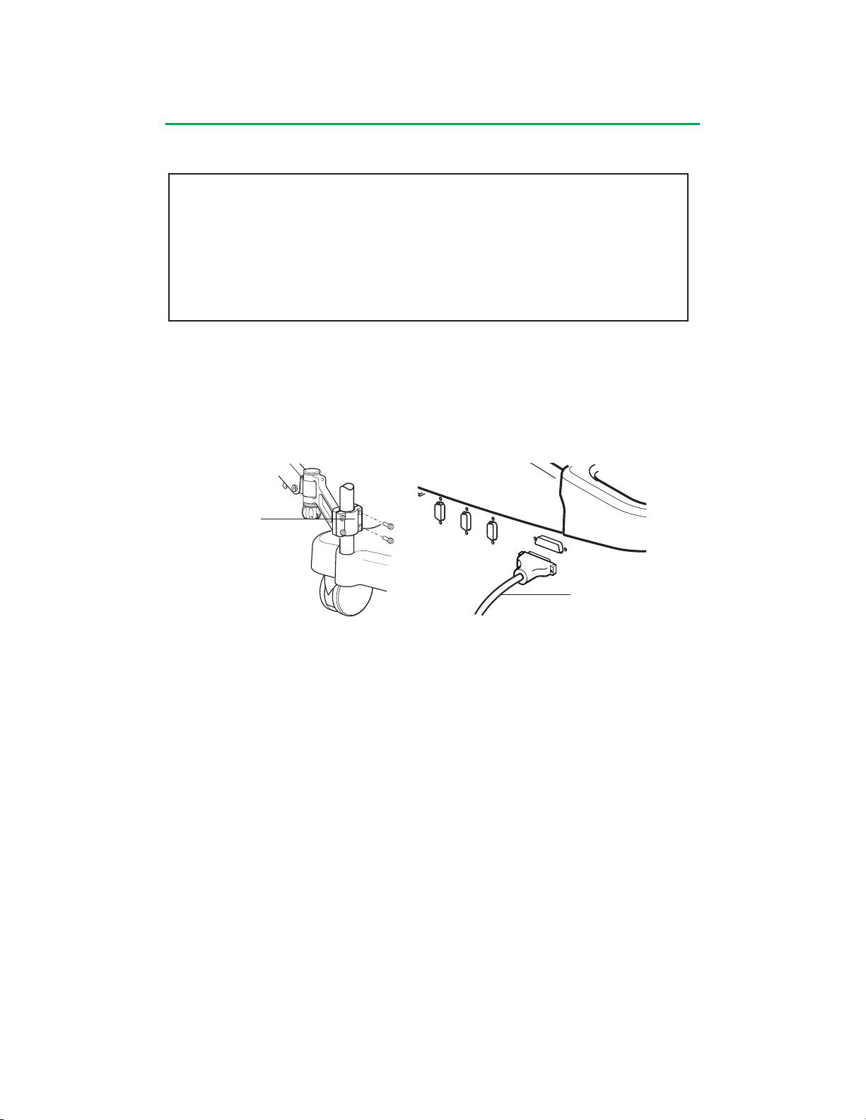
Central Control Monitor
Connect CCM
CAUTION: Use care when handling the Central Control Monitor as the
controls, displays, or circuitry may be damaged if the display is dropped,
struck, or immersed in liquid.
CAUTION: Pump control panels and Central Control Monitor are intended
for hand and gloved hand operation only. Do not use any instruments on
the pump control panels or Central Control Monitor as this may damage the
device.
Attach the CCM bracket to a system pole that will provide easy viewing and access to
the CCM while running a perfusion case.
Make sure AC (Mains) power is OFF before connecting or disconnecting the CCM.
Attach the CCM power cable to one of the receptacles located on the left or right side
of the base, being careful not to damage the connector pins.
CCM Bracket
CCM Power Cable
Before use, check that the CCM is within reach and positioned for maximum visibility.
The display should be positioned within a viewing angle of ± 45° horizontal and ± 30°
vertical; exceeding these viewing angles will decrease the contrast of various colors.
When power to System 1 is turned on, the CCM, the entire system, and attached
modules perform self tests.
4-2
Page 64

Central Control Monitor
Start-Up Messages
If the Power On Self Test fails, the results are displayed continuously at the top of the
Main Screen as long as the Main Screen is displayed or the condition exists. The
failure message is displayed in the following format:
<Module Type Name>: X “Fail”,
where X is the number of modules of this type that failed their Power-On Self-Test.
A maximum of 8 failure messages can be displayed simultaneously. Possible
messages are as follows:
“System Power” “Temperature Sensors”
“System Computer” “Gas System”
“System Network” “CDI 100”
“Air Detectors” “CDI 500”
“Level Detectors” “Large Roller Pumps”
“Occluders” “Small Roller Pumps”
“Pressure Sensors” “Centrifugal Pumps”
“Flow Sensors” “Data Transfer”
The roller pump default direction is set to the system direction during start-up. For
more information on setting system direction, see Configuration, System Settings
in this chapter.
In the event of a System Power, System Computer, System Network, or Gas System
start-up failure, cycle power by turning the Mains Power off and then back on. If the
message is still displayed, contact Terumo Customer Service.
For a roller pump, centrifugal pump, or flow module start-up failure, disconnect and
then reconnect the cable from the back of the pump or module. If the message
appears again, follow the module reassign procedure in this chapter, System tab,
Reassign Module subtab, and contact Terumo Customer Service.
For all other start-up failure messages, disconnect and then reconnect the module
to the module receptacle. If the message appears again, follow the module reassign
procedure in this chapter, System tab, Reassign Module subtab, and contact
Terumo Customer Service.
In the event of a CCM start-up failure, the CCM may lose communication capability
with the system. The message “No System Computer” will be displayed on the
control panels of the roller pumps and centrifugal control unit and the message
“System Computer Needs Service” may appear on the CCM.
4-3
Page 65
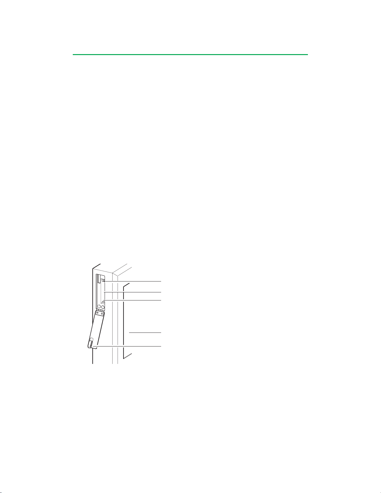
Central Control Monitor
PC Card Compartment
The CCM holds two PC cards: a system configuration card and a service data card.
The system configuration card is used to backup Perfusion Screens and can also
be used to transfer Perfusion Screens between systems and upgrade the CCM and
module software.
The service data card collects and stores data for use by authorized service
representatives.
The system configuration card and service data card are not interchangeable and
must be used in the appropriate slot.
To Install a PC Card:
1. Slide the door latch down to open the compartment door.
2. Insert the PC card into the appropriate slot. The release button above the card
protrudes when the card is fully seated in the slot.
3. Close the compartment door.
To Remove a PC Card:
Ensure the CCM is not accessing the card before removal.
1. Slide the door latch down to open the compartment door.
2. Depress the release button.
3. Remove the card.
4. Close the compartment door.
Release Button
Service Data Card Slot (Right)
System Configuration Card Slot (Left)
Front
Door Latch
4-4
Page 66
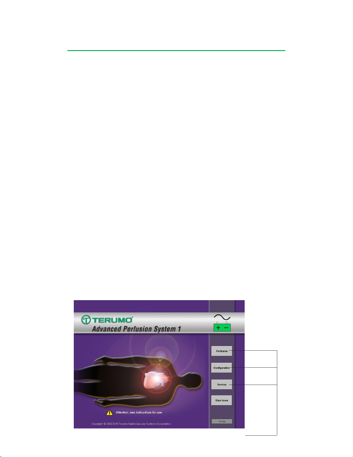
Central Control Monitor
Functional Areas
The CCM has 3 functional areas: Perfusion, Configuration, and Service.
The main screen allows access to these functional areas and provides access to
initiate a controlled system shut down.
The Perfusion area allows the user to select a Perfusion Screen and run a case.
In preparation to run a case, patient information can be entered, calibrations can
be performed, and safety system limits can be checked, modified if needed, and
activated. During use, the CCM can be used to control and monitor all system
modules and devices. The CCM monitors the system for any alert, alarm, error, or
status messages and displays the highest priority message in a dedicated message
area. The user can also initiate advanced functionality such as primary pump
Pulse mode, flow and pressure servo regulation, cardioplegia volume tracking, and
automatic cardioplegia time or volume delivery.
The Configuration area of the CCM is used to define Perfusion Screens including
number and names of modules and devices, assignment of screen icons to physical
devices, safety system connections, and selection of alert and alarm limits. The
displays are organized around a patient graphic representation for identification of
system data.
The Service area is password protected and allows an authorized user to:
• View system log
• Export system logs, module logs, and Perfusion Screens to an external computer
via the service data card
• View module error event data
• Manage security access controls
• View system software version control area
• Upgrade CCM and/or module software
• Calibrate the touch screen.
The Shut down button provides a controlled system shut down and must be used
before turning power off to the system base. Failure to follow the controlled shut
down procedure may result in improper start-up at the next power-on.
4-5
Functional Areas
Page 67

Page 68
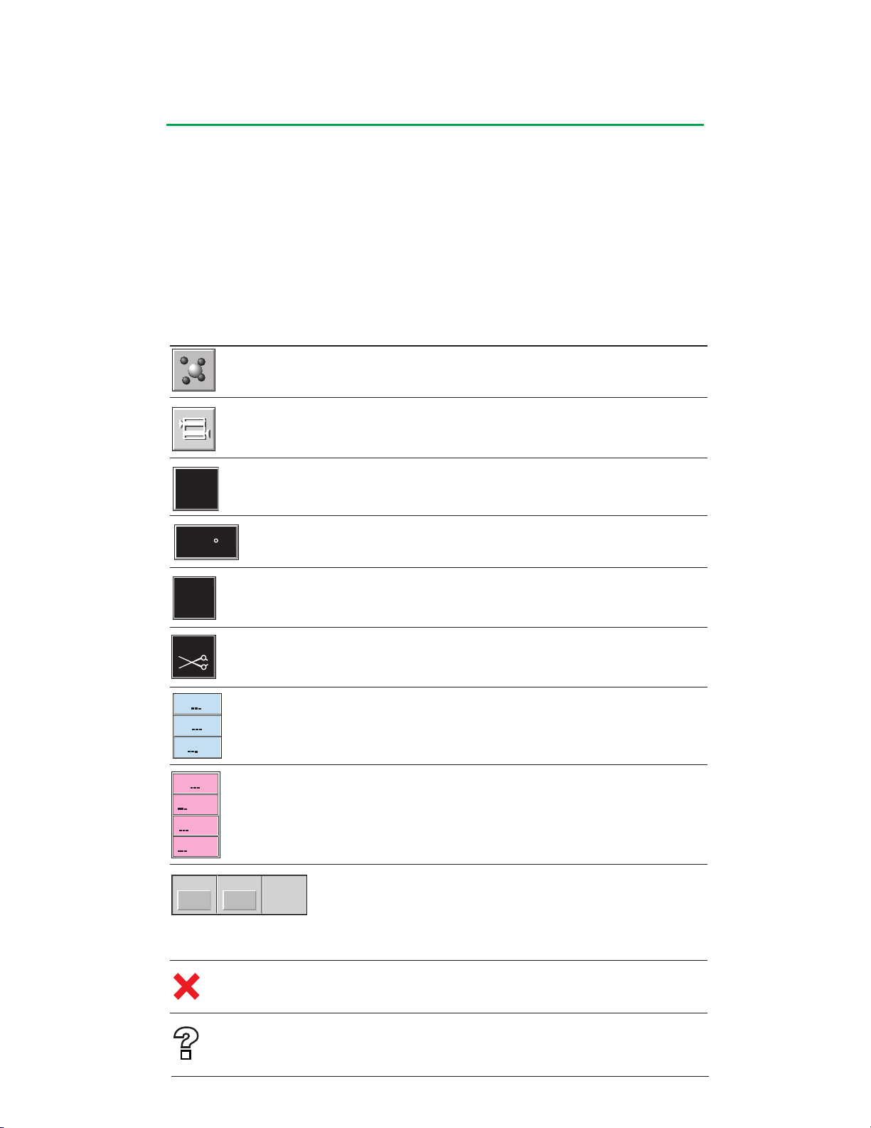
Central Control Monitor
mmHg
C
L/min
0.00
SAT %
HCT %
g/dL
HB
PCO2
K+
pH
mmHg
PO2
mmHg
mmol/L
Gas % O2
FiCO2
0.00
0
0
Displays and Controls
The Graphical User Interface has features and functions common to both of the
Perfusion and Configuration functional areas. The action of the button or icon on the
CCM is initiated when the user lifts the finger from the touch screen.
Ensure that the touch screen cursor arrow is within the perimeter of the button when
using the touch screen. If the cursor arrow is outside the perimeter of the button, the
control or icon will not be activated.
Device Icons and Displays
Icon/Display Device Action when Pressed
Air Detector Opens Air subtab in perfusion screen or selects the
device in configuration.
Level Detector Opens Level subtab in perfusion screen or selects
the device in configuration.
Pressure Sensor Opens Pressures subtab in perfusion screen or
selects the device in configuration.
Temperature Sensor Opens Temp subtab in perfusion screen or
selects the device in configuration.
Flowmeter Opens Flow subtab in perfusion screen or
selects the device in configuration.
Occluder Occluder slide bar appears if hidden, disappears if
displayed in perfusion screen, or selects the device
in configuration.
CDI 100/101 display No action - display only.
CDI 500 display No action - display only.
Electronic Gas When %O2 button pressed, FiO2 slide bar appears
Blender if hidden, disappears if displayed.
When Gas button pressed, Gas slide bar appears if
hidden, disappears if displayed.
FiCO2 display, no action, displays only if using 95/5.
Broken Module Opens Reassign Module subtab. (Refer to
Emergency Procedures chapter, Network
Malfunction for further information.)
Opens Reassign Module subtab. (Refer to
Emergency Procedures chapter, Network
Malfunction for further information.)
Noncommunicating
or missing module
4-6
Page 69
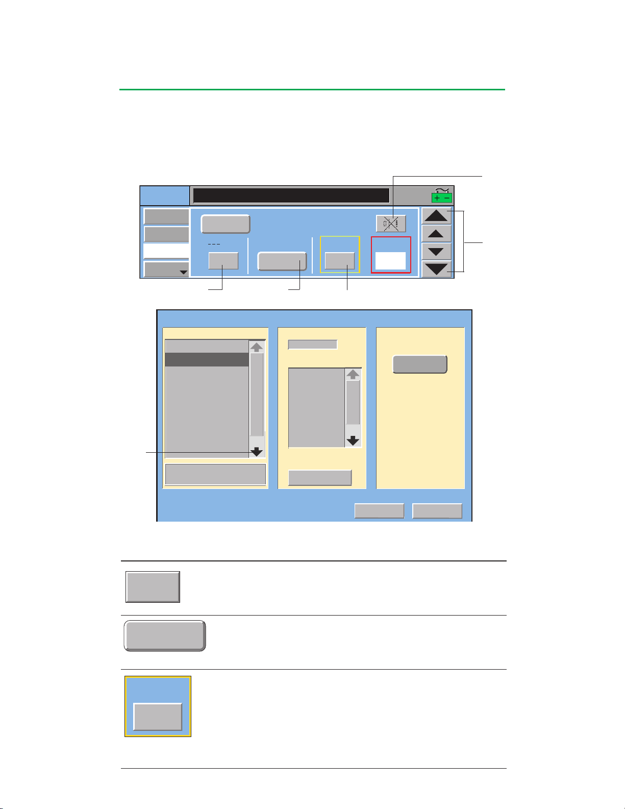
Central Control Monitor
Zero
Average
300
Alert:
Or Enter New Name:
Enter New Name >
To Add Device:
Cancel
Current defined: 0
Maximum allowed:1
Air Detector
Level Detector
Select Device Type:
Occluder
Pressure Sensor
Flow Sensor
Select From List:
Temperature Sensor
CDI 100
CDI 500
Next >
Select Device Name:
Level
VENLevel
CPGLevel
LEVEL1
LEVEL2
Level Detection:
Alert/Alarm
Safety
ART Pres
Average
Air
Next
Pressures
Zero
mmHg
Display:
300 360
Alert:
Alarm:
Level
Limits (mmHg)
16:07:51
Buttons
There are several types of buttons used throughout the Graphical User Interface
screens to select and display information or to accomplish specific tasks. The Safety
tab and To Add Device Screens shown below illustrate examples for a Task button,
Toggle button, Display button, arrows, Mute button, and Scroll arrows.
Mute
Button
Arrows
Toggle ButtonTask Button
Display Button
Scroll Arrows
Button/Display Description Action when Pressed
Task Button Action displayed on the button will
be taken.
Toggle Button Each time the button is pressed, the next
value from a selection list is displayed.
The label that is displayed is the enabled
selection.
Display Button The button background turns white and
value can be adjusted using control arrows
that appear on the right side of the subtab.
The button should be pressed again to
confirm the new value. The control
arrows disappear and other buttons may
be activated when the new value is
confirmed.
4-7
Page 70
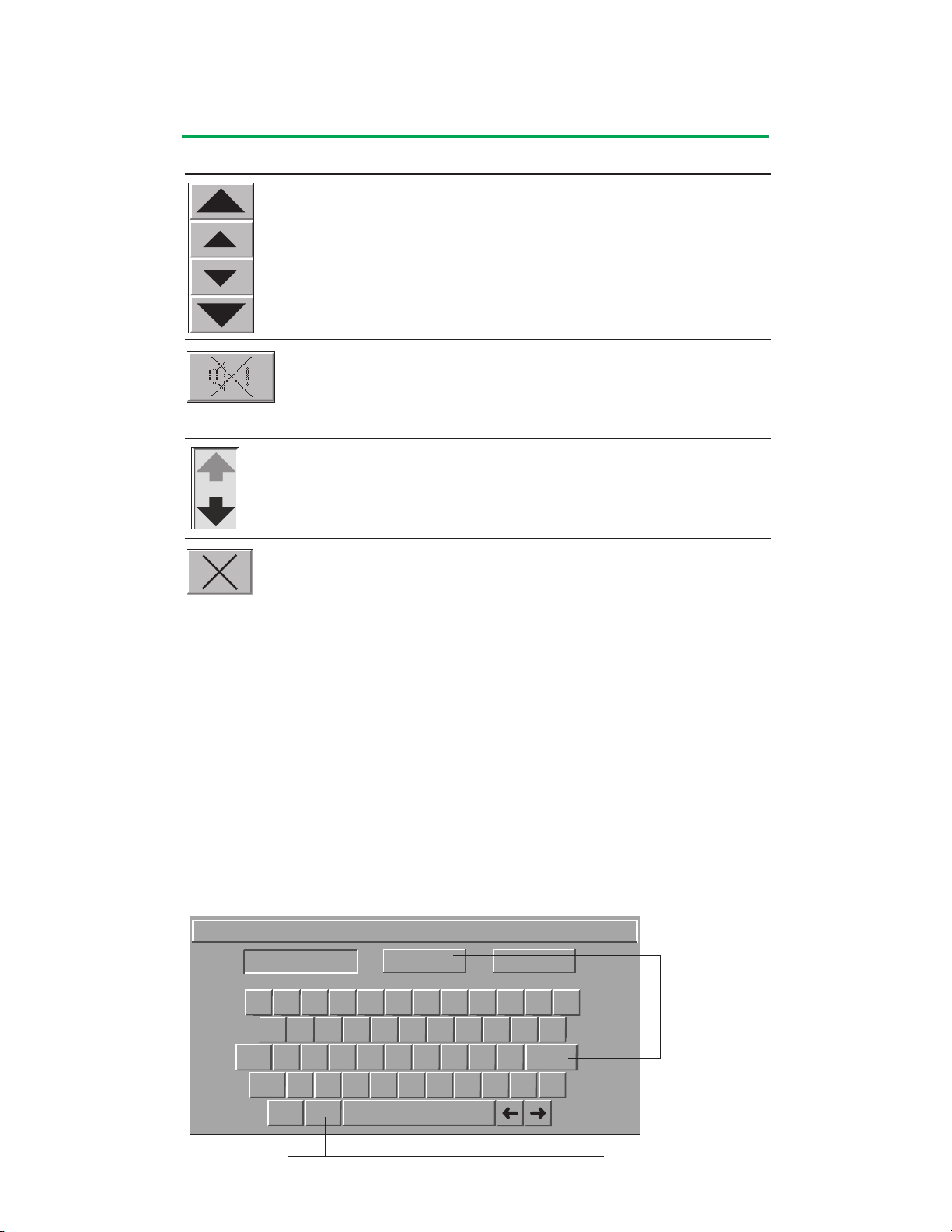
Central Control Monitor
Edit Perfusion Screen Password
Ok Cancel
!1@2#3$4%5^6&7*8(9)0_-+
=
Q
_
-
WERTYUIOP
Caps EnterASDF GH JKL
ZXCVBNMShift
<,>
.
?
/
Back Del
Button/Display Description Action when Pressed
Arrows Appear when a display button is pressed
to adjust the displayed value and
disappear when the new value is stored.
Touching the small arrows adjusts the
selected parameter in small increments;
touching the large arrows adjusts the
selected parameter in large increments.
Mute Button This button appears on all safety subtabs
and is activated by an alert or alarm.
Pressing this button while active silences
the audible alert or alarm tone for that
specific alert or alarm.
Scroll Arrows Enabled when all the items in a list cannot
be viewed within the display area.
Touching the arrows will allow additional
list items to be viewed.
Close Button Use this button to close subtab screen.
Keyboard
The keyboard is used to create and edit passwords and assign names. Please note
the “shift + number” characters are not active.
Passwords are used to limit access to Perfusion Screens and the Configuration area.
A password may contain up to 12 characters, consisting of both upper and lower
case letters, numbers, and the space key.
Perfusion Screen names are used to identify specific screens and may contain up
to 12 characters, consisting of both upper and lower case letters, numbers, and the
space key. Perfusion Screen names must be unique.
Device names are used to identify specific devices and may contain up to 8
characters, consisting of letters both upper and lower case, numbers, and the space
key. Device names must be unique within each Perfusion Screen.
Use Ok or Enter
Use Back and Del to edit input
4-8
Page 71

Central Control Monitor
Security
Password protection can be used to limit access to the Perfusion Screens and the
Configuration area only to authorized users. If no passwords are created, any user
will be able to select any Perfusion Screen or create and modify Perfusion Screen
configurations using the Configuration area.
If the password security feature of the System 1 is used, Terumo Cardiovascular
Systems Corporation recommends including the following elements in any current
security policies and procedures:
•Definition of user levels:
- Who will have access to Perfusion Screens.
- Who will have access to Configuration area.
•Definition of password characteristics:
- Length (e.g., passwords shall contain a combination of at least 6 but no more than
8 alphanumeric characters).
- Characters (e.g., at least one character shall be a number).
- Unique (e.g., each Perfusion Screen shall have a unique password, all of which
shall be different from the Configuration password).
•Description of whether passwords will be changed on a regular basis.
•Identification of the title or name of the person responsible for the creation and/or
modification of passwords.
•Description of how passwords will be communicated to defined users.
•Description of any documentation that will be maintained to demonstrate that the
security procedures are being followed.
•In multilingual settings, only use characters that are common to all keyboards.
4-9
Page 72
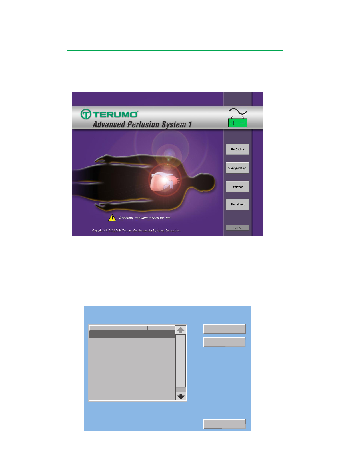
Central Control Monitor
Open
View Summary >
Return to Main
Name
Password:
Choose a Perfusion Screen
CABG Roller
CABG Centrif
Yes
Yes
Min AVR
No
Circ-ARREST
Yes
Pediatric
No
Perfusion Screen
The Perfusion functional area is used to select and run a perfusion case.
Touch the Perfusion button to go to Choose a Perfusion Screen.
The screen lists all Perfusion Screens by name and indicates whether the screen is
password protected. All screens that are password protected require the password to
be entered before the screen will display graphically on the CCM.
The user has three options from this screen:
1. View a summary of a Perfusion Screen.
2. Return to the Main Screen.
3. Open a Perfusion Screen.
4-10
Page 73
CABG ROLLER
Perfusion Screen Summary
Graphic Orientation:
Primary Pump Left - Patient Head Left
Blood Reservoir Type:
Open
Air Detectors:
ART Air
Level Detectors:
Level
Occluders:
Occluder
Pressure Sensors:
ART Pres
CPG Pres
Temperature Sensors:
ART Temp
VEN Temp
Bladder
CPG1 Temp
CDI 500:
CDI 500
Large Roller Pumps:
Arterial
Safety Connections:
esnopseRtnevEeciveD
Level Low Level AlarmStop
Level Low Level AlertMessage 0nly
ART Air Air Detected AlarmStop
ART Pres High Presure AlarmStop
ART Pres High Presure AlertMessage 0nly
CPG
Safety Connections:
esnopseRtnevEeciveD
Arterial Pump Stopped Stop
Arterial Pump Paused Stop
CPG Press High Pressure AlarmStop
CPG Press High Pressure AlertMessage Only
Small Roller Pumps:
Vent
Sucker 1
Sucker 2
Timers:
Pump
Clamp
TMR1
Close
Screen Name
Central Control Monitor
View Summary
The summary screen displays information about the defined
configuration for that Perfusion Screen. The name of the Perfusion
Screen, graphic orientation, type of venous reservoir, devices included
in the Perfusion Screen, and the assigned names of the devices are
displayed. Also included is information about the pumps, such as type,
name, and any safety connections between the pumps and the other
configured devices.
To view a Perfusion Screen Summary:
1. Touch the Perfusion Screen name. The selected screen will be
highlighted.
2. Touch the View Summary button to view a summary of the screen.
3. Select the Close button to return to the previous screen.
To Return to Main:
Touch the Return to Main button to return to the Main Screen.
4-11
Page 74
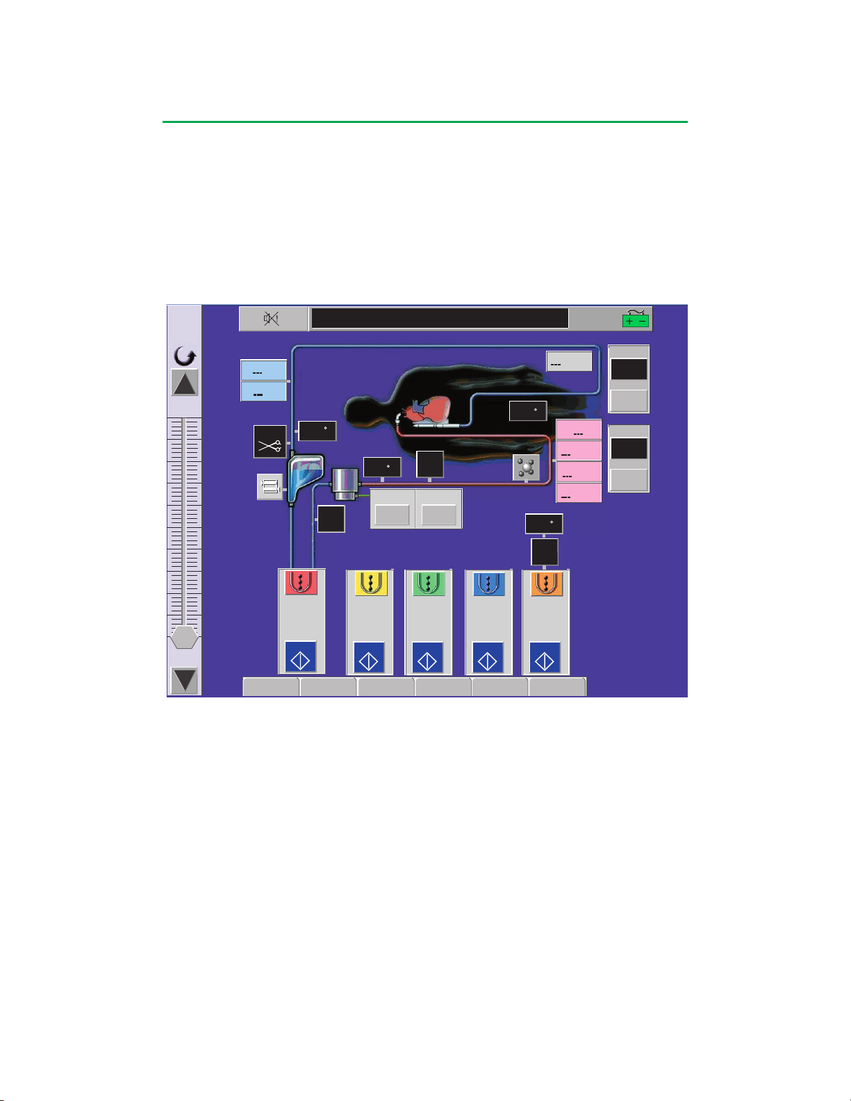
Central Control Monitor
Setup
Safety
CPG
Aux System
Post Case
PCO2
K+
pH
mmHg
PO2
mmHg
mmol/L
16:07:51
Arterial
0.000
L/min
10.78
0
Clamp
Reset
Reset
000:00
Pump
Reset
Reset
000:00
SO2
%
%
HCT
Arterial
L/min
START
Vent
L/min
START
Sucker1
L/min
START
Sucker2
L/min
START
CPG
L/min
START
mmHg
C
mmHg
mmHg
C
C
C
VO2
mL/min
Gas
% O2
00
To Open a Perfusion Screen:
1. Touch the Perfusion Screen name. The selected screen will be highlighted.
2. Touch the Open button.
3. Enter password if the screen is password protected. The CCM will open and
display the Perfusion Screen. When a Perfusion Screen is opened, the status
of all devices that are a part of the Perfusion Screen will change from offline to
online. Online pumps display the pump name and the LED of online modules is
constant green.
Perfusion Screen
Although a Perfusion Screen can be customized to accommodate many different
perfusion setups, all Perfusion Screens share some common characteristics including
the patient and perfusion circuit graphics, message area, system time, power source/
battery status icon, primary pump, pump and clamp timers, pump control area, tabs,
control slide bars, and device icons.
Primary Pump
A Perfusion Screen must have a primary pump, usually the arterial pump, designated
in the Configuration area. The controls and displays for this pump are always
displayed on the right or left side of the Perfusion Screen.
4-12
Page 75
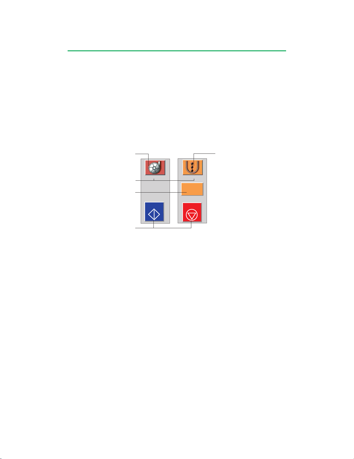
Central Control Monitor
Arterial
L/min
START
CPG
L/min
STOP
0.000
Pump Controls and Displays
Pump control boxes displayed on the lower third of the CCM can be used to start and
stop pumps and to monitor current pump speed or flow values. Each pump has a
corresponding slide bar located either on the right or left side of the Perfusion Screen
which can be used to adjust the pump speed on the CCM. Pumps can also be
controlled from their front panel controls.
Pump Control Box
All pump control boxes consist of three elements: a Start/Stop button, a speed/flow
display button, and a pump icon button. The only exception is a master/follower pump
control box (see Roller Pumps chapter for details of a master/follower pump control
box). The pump type, name, color, display units, and position are all defined in the
CCM Configuration area.
Centrifugal Pump Icon
Pump Name
Speed/Flow Display
Roller Pump Icon
Start/Stop Buttons
Start Button or Stop Button
The Start button activates and starts the pump at a speed of 0 RPM or a flow of
0.000 L/min. The Stop button stops the pump if it is running and also deactivates it.
If the pump is stopped and deactivated using the Stop button, it must be reactivated
using the Start button for the pump to be used again.
To start a pump:
1. Touch the Start button.
• The button color changes to red and the label changes to Stop.
• The pump speed/flow display button appears.
• The pump slide bar appears on one side of the CCM (the primary pump slide bar
is always displayed).
To stop a pump:
1. Touch the Stop button.
• The button color changes to blue and the label changes to Start.
• If the pump is not the primary pump, the speed/flow button and the pump slide
bar disappear.
Pump Speed/Flow Display
The current value of the pump speed or flow rate is displayed in the units selected
during Configuration.
Touching the button on a primary pump will scroll through three possible display
selections: L/min, L/min/m2, or mL/kg/min.
Note: If a centrifugal pump is not configured to display flow through the use of a
flowmeter, the button will display dashes.
For all other pumps, the pump speed/flow display button appears when the pump is
started and disappears when the pump is stopped. Touching the speed/flow display
button will open the slide bar for that pump and close any open slide bar in the
shared location.
4-13
Page 76
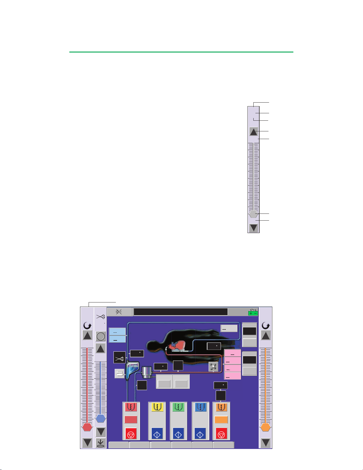
Central Control Monitor
Setup
Safety
CPG
Aux System
Post Case
Arterial
0.000
L/min
10.78
0
Occluder
100
0
CPG
0.000
L/min
3.92
0
0
%Q
16:07:51
Arterial
L/min
Vent
L/min
START
Sucker1
L/min
START
Sucker2
L/min
START
CPG
L/min
PCO2
K+
pH
mmHg
PO2
mmHg
mmol/L
Clamp
Reset
Reset
000:00
Pump
Reset
Reset
000:00
SO2
%
%
HCT
mmHg
C
mmHg
mmHg
C
C
C
VO2
mL/min
Gas
% O2
0
STOP
0.000
0.000
STOP
0
Pump Icon
The symbol on the pump icon button indicates whether a pump is a roller or
centrifugal pump. When the pump is running, the icon will spin in relation to the pump
speed. The roller pump icon also reflects the direction of rotation. Touching the pump
icon button opens the Pump tab. See the Perfusion Screen Tabs, Pumps subtab
section for more details.
0
0
Device Name
Set Point Display
Display Units
Adjustment Arrow
Maximum Value
Scroll Control
Minimum Value
Slide Bars
Slide bars are vertical bars located on either side of the Perfusion
Arterial
RPM
Screen that are used to control roller and centrifugal pump
speeds, occluder position, total gas flow rate, and the FiO2 setting.
All slide bars include a device name, set point display, display
3600
units, adjustment arrows, maximum and minimum value labels,
and a scroll control. The central strip and scroll control are color
coded to match the device color. When operating a slide bar from
a shared location, ensure that the slide bar displayed is for the
device you intend to operate.
To adjust an active slide bar:
1. Touch and hold the slide bar scroll control.
2. Slide the scroll control to the desired slide bar position. The
set point display should display the new setting.
3. Use the adjustment arrows to make fine adjustments.
Each pump has a corresponding slide bar which is used to adjust
its speed on the CCM. While in a Perfusion Screen, the primary
pump slide bar is always displayed and is configured to appear
on the right or left side of the Perfusion Screen. All other pumps share a slide bar
location on the side opposite the primary pump slide bar.
Primary Pump Slide Bar
While in a Perfusion Screen, the primary pump slide bar is always displayed on the
same side as the primary pump. All other pump slide bars appear one at a time in a
single location on the side opposite the primary pump slide bar when the pump speed/
flow display button is pressed.
Primary Pump Slide Bar
4-14
Page 77
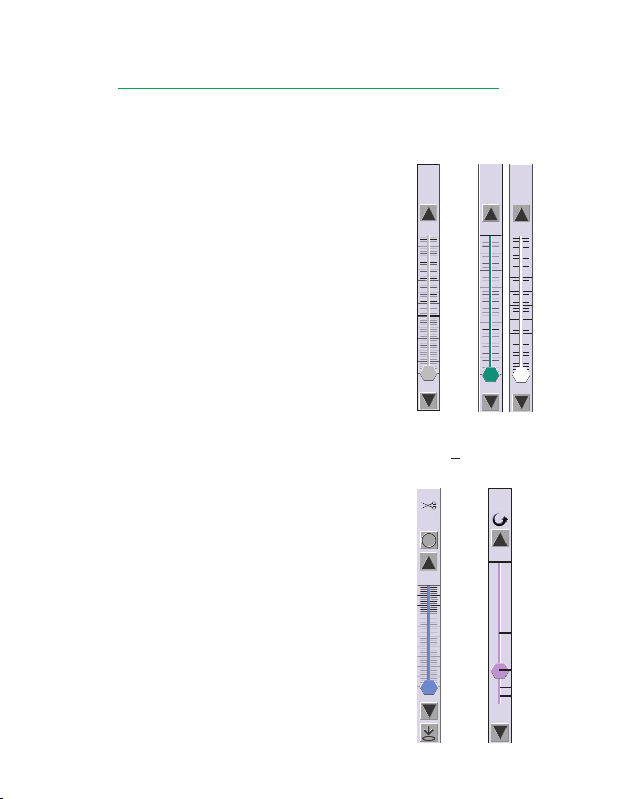
0
%Q
Occluder
100
0
4:1
1:1
0
2:1
8:1
16:1
Cryst
4:1
FiO2
0.21
% O2
1.00
0.21
Gas
0.00
L/min
10
0
21.2
Arterial
0
3600
0
RPM
Central Control Monitor
Roller Pump Slide Bar
A roller pump slide bar includes the roller pump name, current speed or flow rate, a
flow direction icon, a minimum value of 0 and a maximum value determined by the
pump size and selected tube size. The adjustment arrows can be used to adjust the
pump speed by 1 RPM. The corresponding change in flow rate will depend on the
pump size and selected tube size.
Centrifugal Pump Slide Bar
A centrifugal pump slide bar will include the centrifugal pump name,
motor speed in RPM, minimum value of 0 and maximum of 3600
RPM. The adjustment arrows can be used to adjust the motor speed
by 10 RPM.
The bold black horizontal line on the slide bar indicates 1500 RPM.
At the onset of a Coast response, the centrifugal slide bar is disabled
and grayed out for 2 seconds. This occurs even if the Coast response
does not include a speed change.
Note: Using the centrifugal pump slide bar to reduce the pump speed
to 0 RPM will stop and deactivate the pump. Restarting the pump will
required touching start. This is different than the roller pump behavior
which does not stop and deactivate at 0 RPM.
Electronic Gas Blender Slide Bars
Two slide bars are associated with the electronic gas blender: gas flow
and FiO2. The slide bars share one location with the occluder slide
bar. They appear one at a time, adjacent to the primary pump slide
bar when either the gas flow or the FiO2 icons is pressed.
The gas flow slide bar displays the name Gas and the set point flow
rate in L/min. The minimum value is 0 and the maximum is 10 L/min.
The adjustment arrows can be used to adjust the flow rate by 0.1 L/
min.
The FiO2 slide bar displays the name FiO2, the FiO2 setpoint and the
%O2 value from the oxygen analyzer, and the current FiO2 setting.
When the blending gas is air, the minimum value is 0.21 and the
maximum value is 1.00. When the blending gas is 95-5, the minimum
value is 0.95 and the maximum is 1.00.
Occluder Slide Bar
The occluder slide bar appears adjacent to the primary pump slide
bar and shares its location with the gas flow and FiO2 slide bars. The
occluder slide bar will appear when the occluder icon is pressed.
The occluder requires an initial calibration. If the calibration has not
been performed, “CAL” will be displayed at the top of the slide bar and
on the button at the bottom of the slide bar. To calibrate the occluder,
touch the CAL button.
The calibrated occluder slide bar includes the occluder name,
occluder symbol, current value in % open, a full close button, and a
full open button. The minimum value is 0 and the maximum value is
100% open. The adjustment arrows can be used to change the %
open by 1%.
Centrifugal
Pump
Slide Bar
Bold line
indicates
1500 RPM
Electronic
Gas Blender
Slide Bars
Full
Open
Follower Slide Bar
The follower slide bar includes the pump name, the current % of
master flow, and adjustment arrows. The minimum value is 0% and
maximum value is 1:1 or 100%.
4-15
Occluder
Slide Bar
Full
Close
Follower
Slide Bar
Page 78

Central Control Monitor
Displays
The information displayed in the top portion of the Perfusion Screen appears in all
Perfusion Screens. This includes the Mute All button, Message area, Time Display,
and the Power Source/Battery Status icon.
Mute All
All active alert and alarm tones are silenced when the Mute All button is touched with
the exception of the battery alert tone.
Note: The unique, repeating, audible battery alert tone which indicates that the
system is operating from battery power, cannot be muted.
Message Area and Priorities
The message area in the top part of the Perfusion Screen displays the highest priority
alarm, alert, status, or error message. If two conditions of equal priority exist at the
same time, the condition that was detected first will be displayed on the screen. All
messages will post in the Messages subtab within the Aux tab.
In general, the order in which messages are displayed in the Perfusion Screen
message area is determined first by the type of message, then by the order in which
the Central Control Monitor receives the message. Messages are prioritized in order
of importance as:
• Alarms – Flash red
• Alerts – Flash yellow
• Error messages – Flash white
• Status messages – White
If two conditions of equal priority exist at the same time, the message for the
condition that occurred first will be displayed in the message area until it clears. If the
second condition still exists after the first has been cleared, then that message will be
displayed.
For example, if a pressure alert condition is detected and no alarm or other alert
conditions exist, the pressure icon flashes yellow, an audible alert tone sounds, the
Pressures subtab within the Safety tab opens, and the message “<Pressure Name>:
CHECK PRESSURE” is displayed in the message area. If a level alert condition
now occurs, the level icon will flash yellow, the alert tone will sound, but the level
alert message is not displayed in the message area until the pressure alert condition
clears.
Status messages post only once. If the message area has a higher priority message,
the status message will post only in the Messages subtab within the Aux tab.
At any time during the case, the user can view all messages by pressing the Aux tab
and opening the Messages subtab. This subtab displays all system messages along
with the time the message was generated. See the CCM Aux Tab section for further
details.
System Time
The time of day is displayed on the upper right side of the Perfusion Screen. See the
Setup Tab, Time/Date subtab section in this chapter for details on modifying the time
of day.
Power Source/Battery Status Icon
The Power Source/Battery Status icon on the upper right of the Perfusion Screen
provides the user with:
• Power Source – AC or On Battery
4-16
Page 79
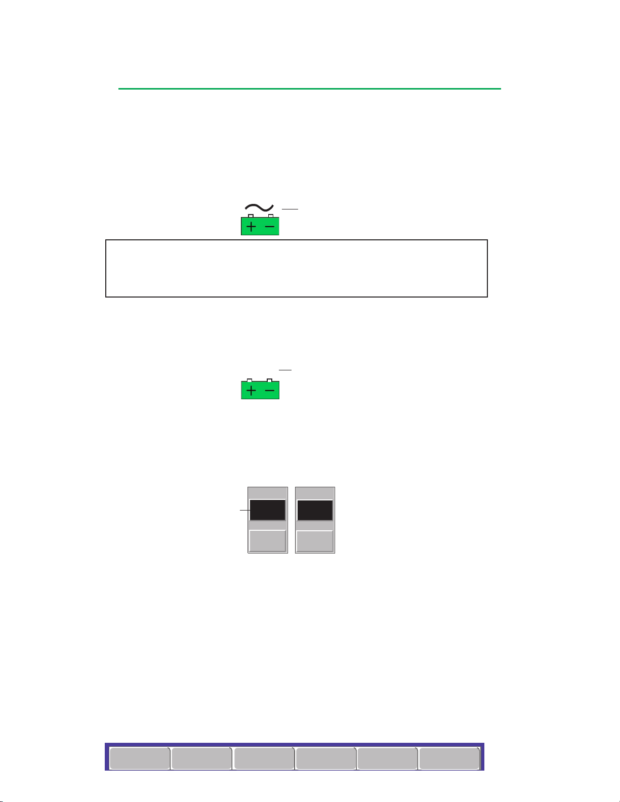
Central Control Monitor
Setup
Safety
CPG
Aux System
Post Case
Clamp
Reset
Reset
000:00
Pump
Reset
Reset
000:00
53 min
53 min
• Estimated battery time remaining in minutes displayed above the Power Source/Battery
Status icon when on battery. An AC (Mains) Power Indicator is shown over the Battery
Status icon when on AC (Mains) Power.
• Estimated battery time remaining as indicated by icon color:
• When on AC (Mains) Power:
• Steady green indicates a battery system with greater than one hour run time
with a fully loaded system
• Steady red indicates a battery system with less than one hour run time with a
fully loaded system.
AC (Mains) Power
WARNING: If the Battery Capacity is indicated at less than 60 minutes battery
power, do not start a case. If the system should be fully charged, but the Battery
Capacity indicates less than 60 minutes, call Terumo Customer Service. Do not
use the system until it has been serviced.
• When on Battery Power:
• Flashing green indicates 30 minutes or more battery life at present discharge rate
• Flashing yellow indicates 15 minutes or more, but less than 30 minutes battery life
at present discharge rate
• Flashing red indicates less than 15 minutes battery life at present discharge rate
On Battery Indicator
Indicator
Pump and Clamp Timers
A pump and clamp timer are always available on the Perfusion Screen. A Perfusion
Screen can be configured to include up to 2 additional timers, for a maximum of 4
timers. The additional timers can be configured to count up from zero or to count
down from a chosen value. Count up timers have a range from 00:00 to 990:59;
count down timers have a range from 990:59 to 00:00. The pump and clamp timer
can only be used in count up mode.
Time Display Area
To operate a timer:
1. Start the timer by touching the Time Display area. The timer starts counting in
minutes and seconds. The start time appears below the Time Display area.
2. To stop the timer, touch the Time Display area again. The stop time appears to
the right of the start time. The Reset button is activated.
3. To restart the timer, touch the Time Display area again. The timer continues
counting from the current value. The stop time disappears.
4. To reset a count up timer to 0 or a count down timer to its initial value, touch the
Reset button. The start and stop times disappear.
Perfusion Screen Tabs
The area of the Perfusion Screen below the pump control boxes displays the 6
Perfusion Screen tabs: Setup, Safety, CPG, Aux, System, and Post Case. An
additional tab, the Pump tab, is accessed by touching the pump icon. Pressing any
one of these opens a screen. Each screen may contain a number of subtabs, which
open additional screens that allow access to more information and functions for
individual sensors and devices.
4-17
Page 80
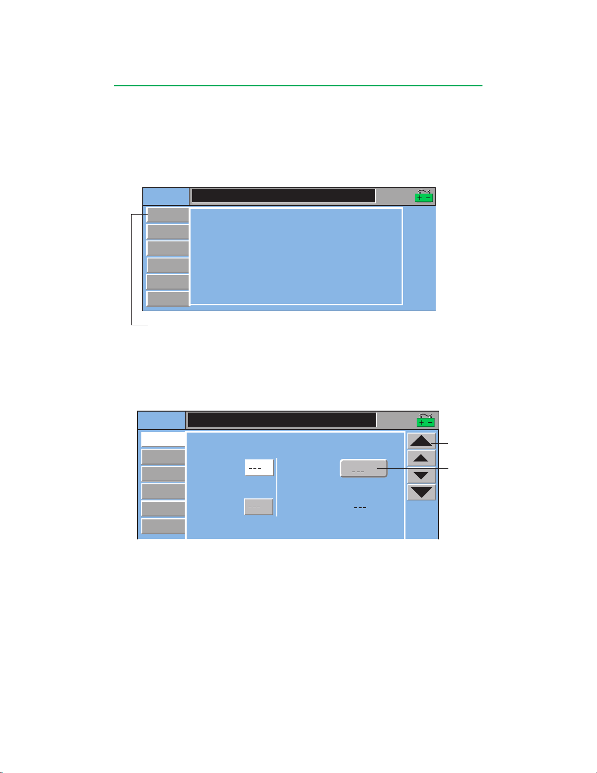
Central Control Monitor
Setup
Gas
16:07:51
Occluders
Time/Date
Timers
Pumps
Patient
Setup
Gas
16:07:51
Height
Occluders
Patient
Time/Date
Timers
Pumps
Dubois
m2
Body
Surface Area
Weight
mL
Blood Volume:
cm
kg
Perfusion Screen Tabs
Setup Tab
The Setup tab contains six subtabs, which allow the user to enter patient data, control
various functions of the gas system, pumps, occluders, and timers, as well as setting
the system time and date.
Subtabs
Patient Subtab
Patient height and weight are entered during the case setup and the patient’s body
surface area and blood volumes are calculated automatically. The patient data
is retained for the current case only and is reset each time a Perfusion Screen is
opened.
Arrows
Choices are:
Dubois
Boyd
Pediatric
To Adjust the Height:
1. Touch the Height button. The Height button changes to white.
2. Use the arrows to enter patient height in cm. The large and small arrows initially
adjust the value to 30 cm. Subsequent adjustments are 20 cm for the large
arrows and 1 cm for the small arrows. The maximum height is 250 cm.
3. Touch the Height button again to store the new value.
To Adjust the Weight:
1. Touch the Weight button. The Height button changes to white.
2. Use the arrows to enter patient weight in kg. The large arrows adjust the value
by 2 kg up to 20 kg, then adjust the value by 20 kg increments. The small arrows
value. The maximum weight is 300 kg.
adjust the value by 0.1 kg or 1 kg and correspond to the large arrow increment
3. Touch the Weight button again to store the new value.
4-18
Page 81
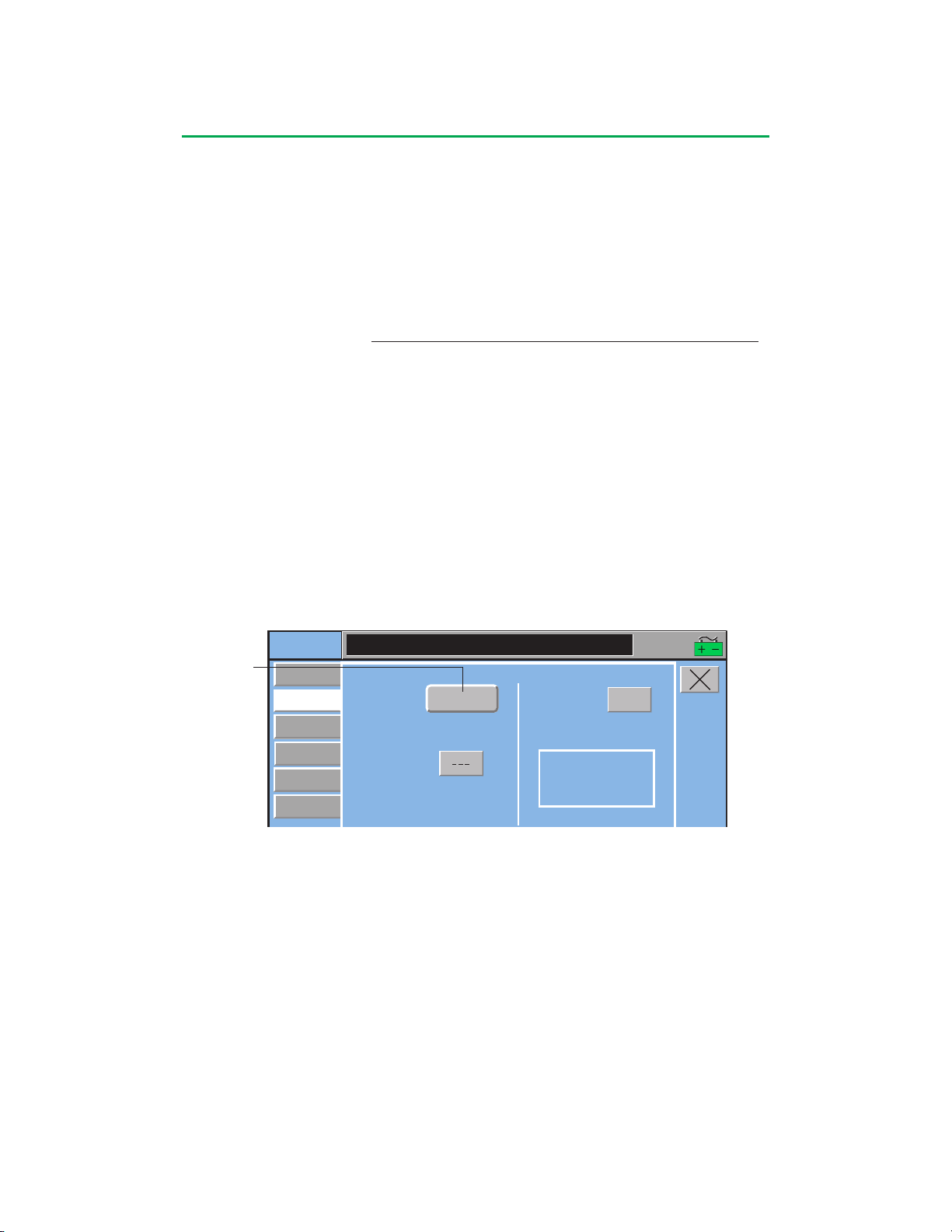
Central Control Monitor
Body Surface Area (BSA)
The BSA is calculated automatically when the height and weight data are entered.
Touch the Body Surface Area button to toggle through the selection for the formula
used to calculated the BSA. BSA can be calculated using the Dubois, Boyd, or
Pediatric formulas.
The Dubois formula is BSA = (Height)
.725
The Boyd formula is BSA = 3.207 (Height)
x (Weight)
0.3
x (Weight x 1000)
.425
x 0.007184.
(0.7285 – 0.0188 Log (Weight x 1000))
10000
The Pediatric formula is BSA = (Wt
.5378
x Ht
.3964
) x 0.024265.
Blood Volume
The Blood Volume is automatically calculated using the patient weight information
and is displayed in milliliters. If the patient weight is greater than or equal to 20 kg,
the formula used is 70 mL x Wt (kg). If patient weight is greater than or equal to 10 kg
and less than 20 kg, the formula is 75 mL x Wt (kg). If the patient weight is less than
10 kg, the formula is 80 mL x Wt (kg).
Gas Subtab
From the Gas subtab, the user selects the type of gas to blend with O2, sets the low
FiO2 alarm and calibrates the oxygen analyzer. See the Electronic Gas Blender
chapter for detailed information about connecting and operating the gas blender.
Choices are:
Air
95/5
Setup
Patient
Gas
Pumps
Occluders
Timers
Time/Date
02 Blend:
Low FiO2 Alarm:
Air
O2 Analyzer:
Calibration Status:
Not Calibrated
16:07:51
Calibrate
To Select O2 Blend:
Touch the O2 Blend button to toggle between Air and 95/5. The O2 blend selected
(95/5 or Air) will be displayed within the button.
To Set Low FiO2 Alarm:
1. Touch the Low FiO2 Alarm button. The button changes to white.
2. Use the arrows to change the alarm limit. The large arrows adjust the FiO2 limit
by increments of 0.5 and small arrows adjust the limit by increments of 0.1.
3. Touch the Low FiO2 Alarm button again to store the new value.
Note: The low FiO2 Alarm is retained for the current case only and is reset each time
a Perfusion Screen is loaded.
With air selected as the O2 blend, the Low FiO2 Alarm defaults to “---” and has a
range of 0.21 - 0.99. With 95-5 selected as the O2 blend, the Low FiO2 Alarm defaults
to “---” and has a range of 0.95 – 0.99. Asterisks are displayed and the alarm is
disabled if the alarm limit is set lower than the default value.
4-19
Page 82
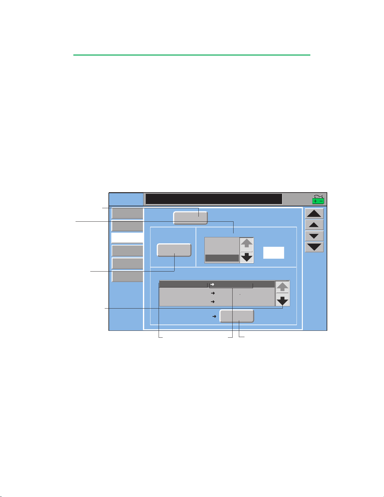
Setup
Gas
Display Units:
Occluders
Patient
Time/Date
Timers
Pumps
Pump Response:
Events
Pump:
Arterial
Type: Large Roller Pump
Tube Size:
Custom
Custom
S4:1
S8:1
ART Pres Pres Alert Reduce Speed : 300 mmHg
ART Pres Pres Alarm Stop : 360 mmHg
ART Flow Back Flow
Stop
ART Pres Pres Alarm
Stop
16:07:51
FC144
Flow Constant
L/min
L/min
Tube Size Box
1/8 in.
3/16 in.
1/4 in.
5/16 in.
3/8 in.
7/16 in.
1/2 in.
6mm
8mm
10mm
12mm
Central Control Monitor
To Calibrate O2 Analyzer:
Touch the Calibrate button.
• Calibration takes approximately 2 minutes.
• “Calibrating O2 analyzer” is displayed during calibration.
When the calibration is complete, the message “O2 Analyzer Calibration Complete”
will display in the Messages subtab within the Aux tab and in the message area of the
CCM if there are no higher priority messages.
Pumps Subtab
The Pumps subtab allows the user to change the roller pump display units, tube size,
and pump response to a safety event. The Pumps subtab also allows the user to
change centrifugal pump display units, pump response to a safety event, and set the
minimum flow alarm. See the Roller Pumps or Centrifugal Control Unit chapter for
detailed information about connecting and operating pumps.
For Roller Pumps
Touch the Pump button until the correct name is displayed on the button. The roller
pump must be in Stop mode to change the display units and the tube size.
Pump Button
S1:1
S2:1
S4:1
S8:1
Custom
Display Units Button
• L/min
• RPM
• L/min/m
• mL/kg/min
Only 3 events can be viewed
at one time. Use scroll arrows
to view other configured events
and pump response.
2
}
Primary
Pump Only
To Change Display Units:
Touch the Display Units button to toggle through the selections. Stop when the
desired selection is displayed. Changes are only retained for the current case.
To Change Tube Size:
1. Use the scroll arrows to view the list of available sizes.
2. Touch the correct tube size from the list. The tube size selection is highlighted
The system will retain this selection until a new selection is made from this
Device Name
and Event
Response
Response Selection Button
and the tube size will display above the selection box and on the roller pump local
display.
To enter a custom tube size:
1. Select Custom from the list.
2. Touch the Flow Constant button.
3. Use arrows to adjust value.
4. Touch button again to retain the value.
screen or from the pump local display.
4-20
Page 83
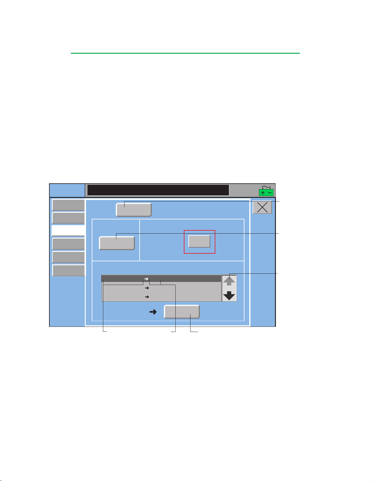
Central Control Monitor
Only 3 events can be viewed at
one time. Use scroll arrows to
view other configured events
and pump response.
and Event
To Change Pump Response:
The bottom portion of the screen displays the configured safety connections and
gives the user the ability to edit them for the current case only.
1. Select the event/pump response to be changed. The Response button at the
bottom of the screen displays the current pump response.
2. Touch the Response button to toggle through the list of available response
choices. The response that is displayed on the button is the response of the
pump for the specified event.
Changes made to pump response from the Perfusion Screen are only retained for the
current case. The response will revert to the response set in Configuration when the
case is exited.
For Centrifugal Pumps
Touch the Pump button until the correct name is displayed on the button. Changes
can be made while the pump is operating.
Setup
Patient
Gas
Pumps
Occluders
Timers
Time/Date
Pump:
Display Units:
Events
Level Level Alarm Stop
Level Level Alert Message Only
ART Air Air Alarm
Level Level Alarm
Device Name
L/min
Arterial
Min Flow Alarm
(L/min):
Pump Response:
Stop
Response
Type:
Centrifugal Pump
1.0
Stop
Response Button
16:07:51
Change Display Units:
Touch the Display Units button to toggle through the choices. Stop when the desired
selection is displayed. Changes are retained for the current case only.
Pump Button
Display Units Button
Primary Pump
only with a
configured
flowmeter
• RPM
• L/min
• L/min/m
{
• mL/kg/min
2
Set Min Flow Alarm:
The Min Flow Alarm button is only available when a flowmeter has been placed on
the centrifugal pump icon. The range for the Min flow alarm is 0.0 to 8.0 L/min.
1. Touch the Min Flow Alarm button.
2. Use the arrows to adjust the minimum flow value. The large arrows adjust the
value by 1 L/min and the small arrows adjust the value by 0.1 L/min.
3. Touch the Min Flow Alarm button again to store the new value.
4-21
Page 84
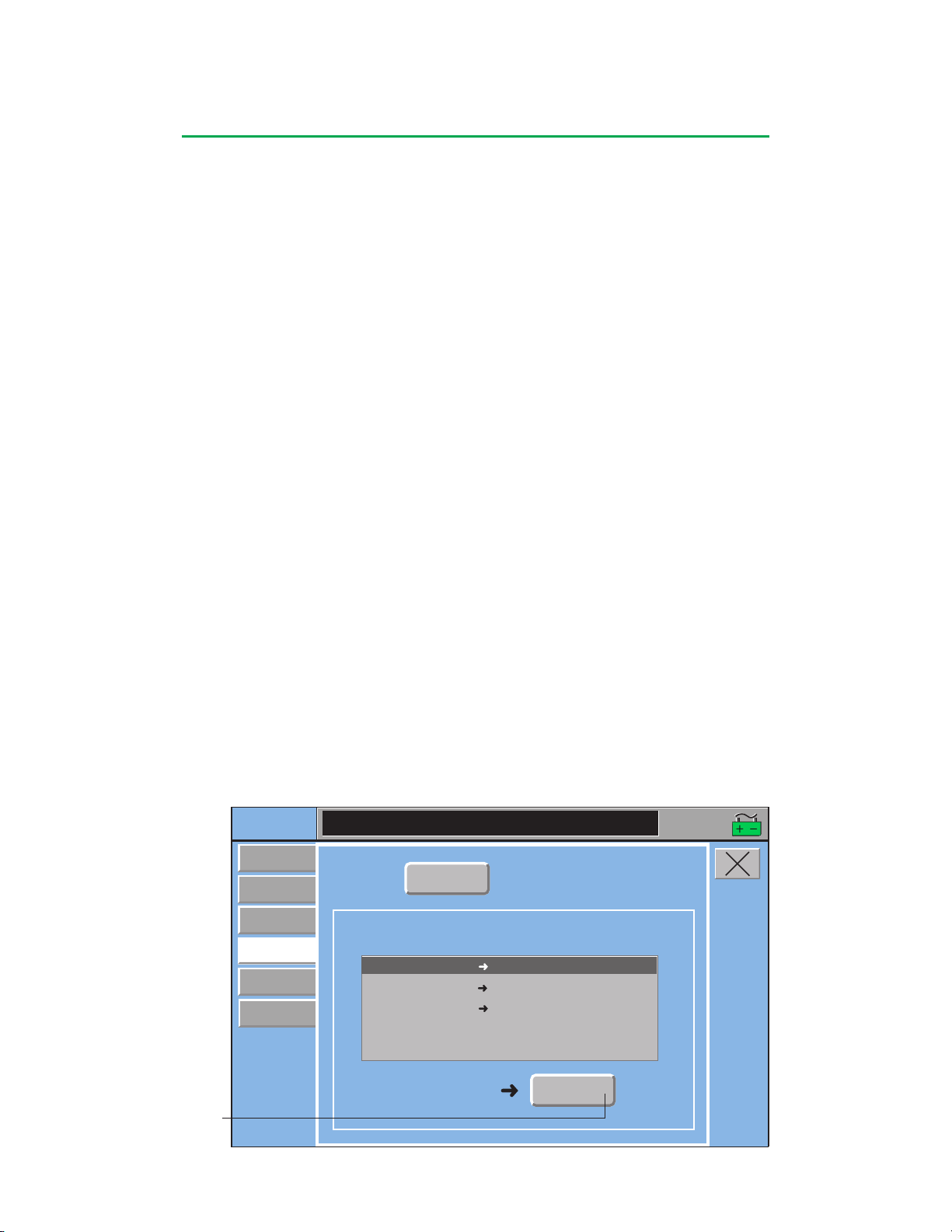
Central Control Monitor
Setup
Gas
Occluders
Patient
Time/Date
Timers
Pumps
Arterial Pump Stop
Events
Occluder:
Occluder
Full Close
3/8 in.
Arterial Pump Start Full Open
Arterial Pump Stop Full Close
Arterial Pump Pause
Full Close
Occluder Response:
16:07:51
To Change Pump Response:
The bottom portion of the screen displays the configured safety connections and
gives the user the ability to change them for the current case.
1. Select the event/pump response to be changed. The Response button at the
bottom of the screen displays the current pump response.
2. Touch the Response button to toggle through the list of available response
choices. The response that is displayed on the button is the response of the
pump for the specified event.
Changes made to pump responses from the Perfusion Screen are only retained for
the current case. The response will revert to the response set in Configuration when
the case is exited.
Occluders Subtab
From this subtab, the user can change an occluder response to an external event
generated by the primary pump. The name of the occluder will be displayed on the
Occluder button.
Occluder responses to the following centrifugal pump events must be the same:
pump stop, pump Coast, and minimum flow. The system will automatically assign the
response chosen for stop, Coast, or minimum flow to the other two events.
To Change Occluder Response:
1. Select the event/response to be changed. The Response button at the bottom of
the screen displays the current occluder response.
2. Touch the Response button to toggle through the list of available response
choices. Occluder response choices include No Response, Full Open, Full
Close, or Go to % Flow. The response that is displayed on the button is the
response of the occluder for the specified event. If Go to % Flow is a response
that is selected, touch the 0% button. Use the arrows to adjust the value. Large
arrows adjust the value by 10% and small arrows adjust the value by 1%.
Changes made to a safety response from the Perfusion Screen are only retained for
the current case. The response will revert to the response set in Configuration when
the case is exited.
Response Button
4-22
Page 85
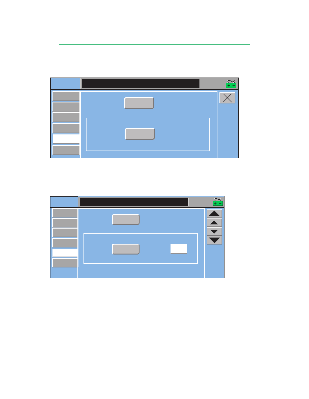
Central Control Monitor
Setup
Gas
Timer:
Occluders
Patient
Time/Date
Timers
Pumps
Type:
Clamp
16:07:51
Count Up
Count Up
Setup
Gas
Timer:
Occluders
Patient
Time/Date
Timers
Pumps
Type:
TMR1
010:00
Start Value:
16:07:51
Count Down
Count Down
Timers Subtab
From this subtab, the user can check the mode of a timer. The Pump and Clamp
timers are controlled from the Perfusion Screen. Other timers are controlled from the
Timers subtab within the Aux tab.
For Count Up Mode:
The timer is ready for use.
For Count Down Mode:
Timer Button
Type Button
Start Value Button
1. Touch the Start Value button.
2. Use the arrows to set the start value. The large arrows adjust the value by 1
minute, the small arrows adjust the value by 1 second. The maximum value that
can be entered is 990:59.
3. Touch the Start Value button to store the value.
4-23
+ 1 min
+ 1 sec
– 1 sec
– 1 min
Page 86
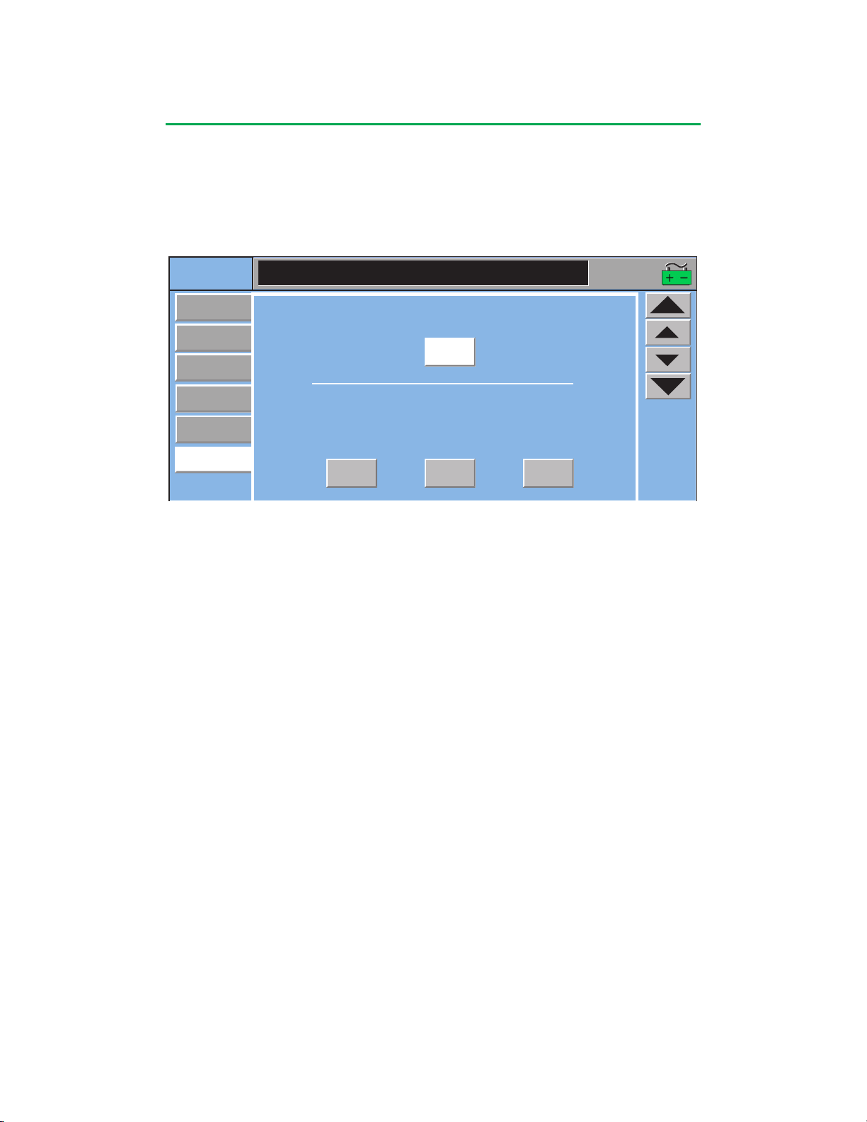
Central Control Monitor
Setup
Gas
16:07:51
Time:
Occluders
Patient
Time/Date
Timers
Pumps
Day
Year
09:58
01 29 2002
Month
Date:
Time/Date Subtab
The time is displayed in the upper right corner of the Perfusion Screen. The date
appears in various locations throughout the Perfusion, Configuration, and Service
functional areas. Both the time and date are set from the Time/Date subtab. Please
note that all pumps and timers must be stopped in order to change the time and/or
date.
To Change the Time:
1. Touch the Time button. The button will turn white.
2. Use the large arrows to adjust the hour and the small arrows to adjust the
minutes.
3. Touch the button again to store the new value.
To Change the Date:
1. Touch the Month button. The button will turn white.
2. Use the arrows to adjust the value. The large arrows adjust the value by 3 and
the small arrows adjust the value by 1.
3. Touch the button again to store the new value.
4. Touch the Day button. The button will turn white.
5. Use the arrows to adjust the value. The large arrows adjust the value by 5 and
the small arrows adjust the value by 1.
6. Touch the button again to store the new value.
7. Touch the Year button. The button will turn white.
8. Use the arrows to adjust the value. The large arrows adjust the value by 5 and
the small arrows adjust the value by 1.
9. Touch the button again to store the new value.
4-24
Page 87
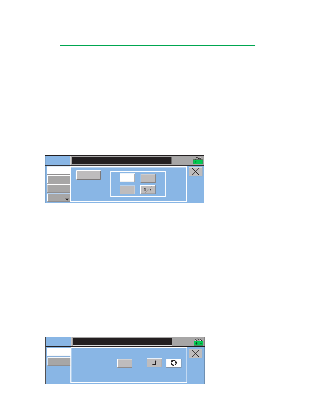
Central Control Monitor
Safety
ART Air
Next
Reset
Air
Pressures
Off
On
16:07:51
Level
CPG
Auto Dose
Setup
Delivery
Time Since Last Delivery:
000:00
mL
Current Delivery:
0
0mL
Deliver:
Recirculate:
Total Delivery:
16:07:51
Safety Tab
There are 5 subtabs within the Safety tab: Air, Level, Pressure, Temperature, and
Flow. If a device type was not configured for the Perfusion Screen, the name on the
subtab for that type of module cannot be selected. Use the Previous or Next buttons
to scroll through the subtabs.
Access an area by touching the subtab or by touching the device icon on the
Perfusion Screen.
If more than one sensor for a device type is assigned to a Perfusion Screen, toggle
through the sensor names by touching the button.
A Mute button appears in all the Safety subtabs. The Mute button becomes available
when the selected safety device has an active alarm or alert and will silence the
audible tone when pressed. If there is no active alarm or alert, the Mute button is
unavailable.
Touch the Mute Button to
silence an active alert or alarm
For detailed information about operating safety systems from the CCM, see the
module chapters:
• Air Bubble Detection
• Level Monitoring
• Pressure Monitoring
• Temperature Monitoring
• Flow Monitoring
CPG Tab
If a pump was identified as the cardioplegia pump during perfusion screen
configuration, this tab can be used to track cardioplegia volume delivery and can be
set up to deliver up to three separate cardioplegia doses based on delivery volume or
delivery time.
Delivery Subtab
The Delivery subtab calculates the current and total accumulated volume delivered
by the cardioplegia pump, based on the pump speed and tube size. A timer displays
the time since last delivery between cardioplegia doses. The Deliver and Recirculate
mode buttons enable and disable the cardioplegia volume tracking.
4-25
Page 88
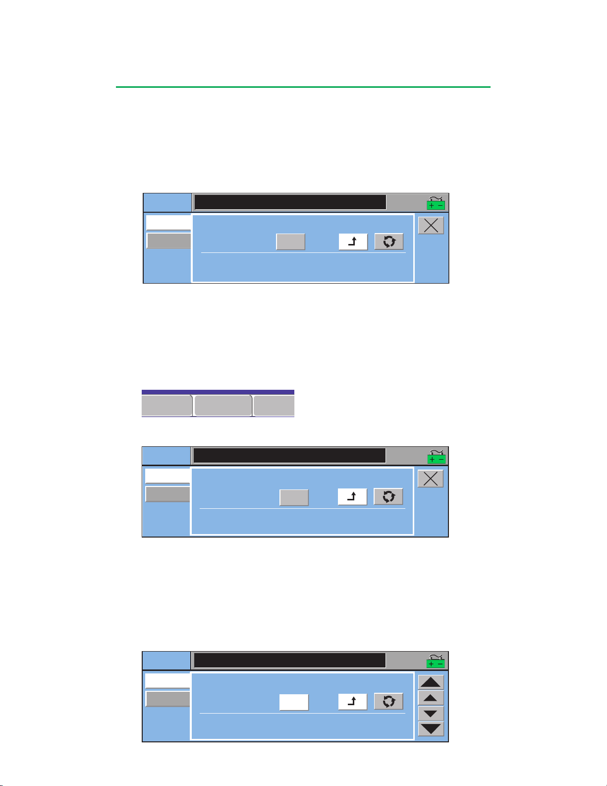
Central Control Monitor
CPG
Aux System
Post Case
001:18
CPG
Auto Dose
Setup
Delivery
Time Since Last Delivery:
000:00
mL
Current Delivery:
0
0 mL
Deliver:
Recirculate:
Total Delivery:
16:07:51
CPG
Auto Dose
Setup
Delivery
Time Since Last Delivery:
001:18
mL
Current Delivery:
1000
1000 mL
Deliver:
Recirculate:
Total Delivery:
16:07:51
CPG
Auto Dose
Setup
Delivery
Time Since Last Delivery:
001:18
mL
Current Delivery:
1000
1000 mL
Deliver:
Recirculate:
Total Delivery:
16:07:51
Deliver Mode
To start tracking cardioplegia delivery:
1. Select Deliver mode by pressing the Deliver button.
2. Start the cardioplegia pump. The cardioplegia pump must be in L/min mode for
total flow rate to be displayed on the CCM and pump local display.
• The system tracks and displays the volume for Current Delivery and Total Delivery.
• The Total Delivery value is grayed out indicating that it cannot be modified.
To stop cardioplegia delivery:
1. Touch the cardioplegia pump Stop button.
• Volume tracking stops.
• Time Since Last Delivery is set to 0 and the timer starts counting the time since
last delivery.
• If the subtab is closed while the timer is active, the time since last delivery is
displayed on the CPG tab on the CCM.
• The Total Delivery value is displayed in black indicating that it can be modified.
To modify the Total Delivery volume:
1. Touch the Total Delivery button. The button background turns white.
2. Use the arrows to adjust the total volume. The small arrows change the volume
by 10 mL, the large arrows change the volume by 100 mL.
3. Touch the Total Delivery button again to store the new Total Delivery value.
• The adjustment arrows disappear and the Total Delivery button background turns
gray.
4-26
Page 89
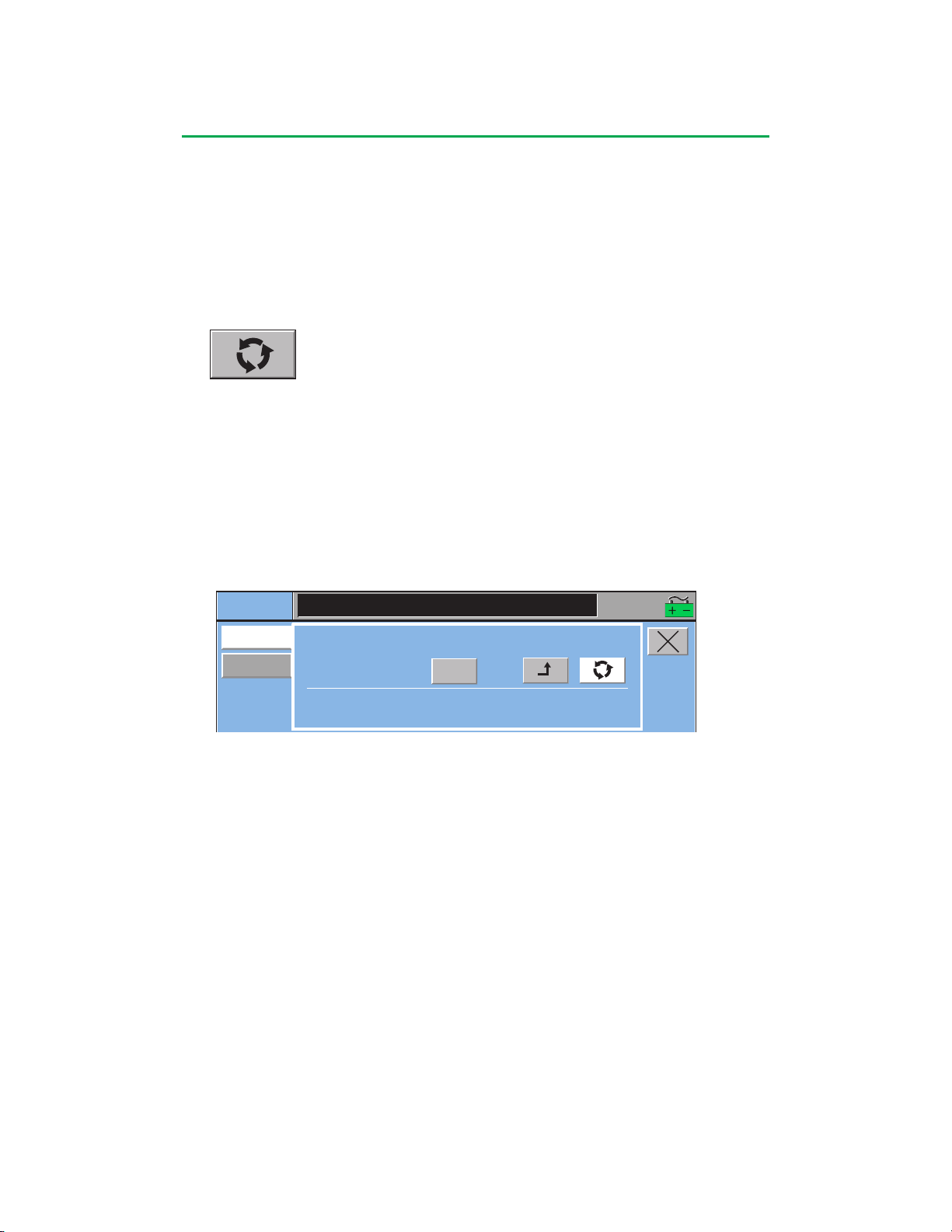
Central Control Monitor
CPG
Auto Dose
Setup
Delivery
Time Since Last Delivery:
2:10
mL
Current Delivery:
401
1401 mL
Deliver:
Recirculate:
Total Delivery:
16:07:51
Resume cardioplegia delivery:
1. Restart the cardioplegia pump.
• The Time Since Last Delivery timer stops.
• The Current Delivery value is set to 0 and the system tracks the volume for
Current Delivery and the accumulated volume for Total Delivery.
• The Total Delivery value is grayed out indicating that it cannot be modified.
Recirculate Mode
In Recirculate mode, cardioplegia volume tracking is disabled to allow the
cardioplegia pump to run without tracking the volume. This may occur when the
volume is being recirculated, but not delivered to the patient.
To use Recirculate Mode:
1. Select Recirculate mode by pressing the Recirculate button.
2. Start the cardioplegia pump.
• Volume is not tracked.
• Time Since Last Delivery timer continues counting.
• Total Delivery value is displayed in black indicating that it can be modified.
To Switch from Recirculate to Deliver Mode:
1. Select the Deliver mode by pressing the Deliver button.
• If the cardioplegia pump is running:
n
Time Since Last Delivery timer stops.
n
The Current Delivery value is set to 0 and the system tracks the volume for
Current Delivery and the accumulated volume for Total Delivery.
n
The Total Delivery value is grayed out indicating that it cannot be modified.
• If the cardioplegia pump is in Stop mode:
n
The Current Delivery value is set to 0.
To Switch from Deliver to Recirculate Mode:
1. Select Recirculate mode by pressing the Recirculate button.
• If the cardioplegia pump is running:
n
Volume tracking stops.
n
Time Since Last Delivery is set to 0 and the timer starts counting the time since
last delivery.
n
If the subtab is closed while the timer is active, the time since last delivery is
displayed on the CPG tab button on the CCM.
n
The Total Delivery value is displayed in black indicating that it can be modified.
• If the cardioplegia pump is in Stop mode:
n
No changes occur.
4-27
Page 90
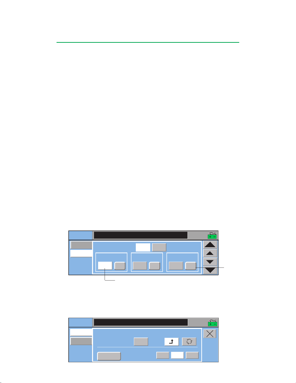
Central Control Monitor
CPG
Auto Dose
Setup
Delivery
Automatic Dose Delivery:
1000
Induction Dose:
Hide
0
mL
mL
mL
Maintenance Dose:
Other Dose:
16:07:51
View
0
CPG
Auto Dose
Setup
Delivery
Time Since Last Delivery:
11:48
mL
Current Delivery:
63
mL
Deliver:
Recirculate:
Total Delivery:
Auto Dose Select:
mL
137
Auto Manual
16:07:51
1614
1614
Reset
Reset
Maintenance
Maintenance
Automatic Dose Delivery
The Automatic Dose Delivery feature is used to select one of three cardioplegia
doses that automatically stop the pump once the dose has been delivered. This
feature is set up and enabled using the Auto Dose Setup subtab.
Refer to the Roller Pumps chapter, Roller Pump Messages section for details on
messages which will display in the display area on the front panel of the cardioplegia
pump.
Auto Dose Setup Subtab
View and Hide Buttons
Enable the Auto Dose Delivery feature:
1. Touch the View button (default is Hide).
• View button background turns white. The Hide button background turns gray.
• Auto Dose Screen appears on the lower half of the Delivery subtab.
Disable the Auto Dose delivery feature:
1. Touch the Hide button (default is Hide).
• Hide button background turns white. The View button background turns gray.
• Lower half of the Delivery subtab is blank.
Dose Setup
For each selection, Induction Dose, Maintenance Dose, and Other Dose:
1. Touch the Dose toggle button to display the desired units – mL or time (minutes
and seconds).
2. Touch the Dose Value button.
• The Dose Value button turns white. Adjustment arrows appear.
3. Use the arrows to modify the Dose Value. For mL, the small arrows change the
volume by 10 mL and the large arrows by 100 mL. For time, the small arrows
change the time by 1 sec and the large arrows change the value by 1 min.
4. Touch the Dose Value button again to confirm the value.
• The adjustment arrows disappear. The Dose Value button background turns gray.
• If the View button has been pressed, the value corresponding to the Auto Dose
selection appears on the Delivery subtab.
When Automatic Dose Delivery is enabled, the lower half of the Delivery subtab
displays a toggle button for selecting the auto dose, a Reset button to reset the dose
value after the automatic dose has been delivered, and two mode buttons - Auto
and Manual - used to initiate and stop auto dose delivery. The dose value cannot be
changed while the dose is being delivered.
Dose Value Button
Dose Toggle
Button
• mL
• Time
4-28
Page 91
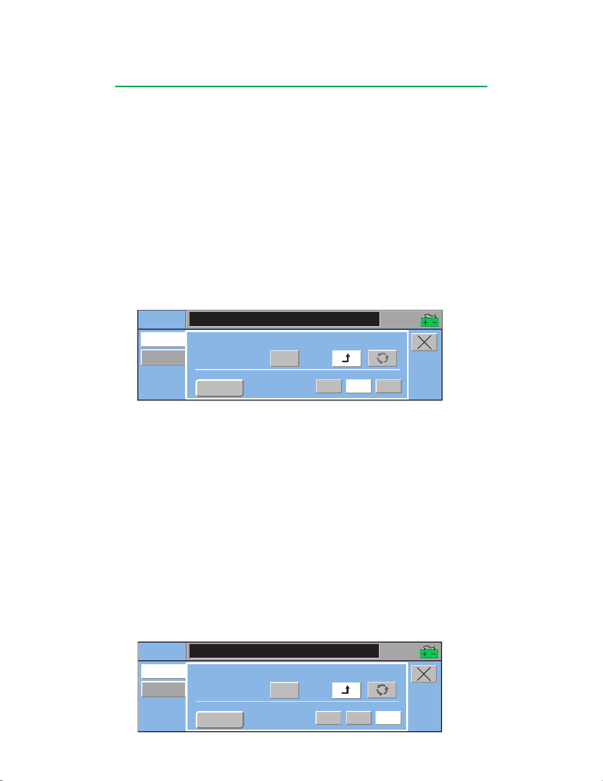
Central Control Monitor
CPG
Auto Dose
Setup
Delivery
Time Since Last Delivery:
11:48
mL
Current Delivery:
63
mL
Deliver:
Recirculate:
Total Delivery:
Auto Dose Select:
mL
137
Auto Manual
16:07:51
1614
1614
Reset
Reset
Maintenance
Maintenance
CPG
Auto Dose
Setup
Delivery
Time Since Last Delivery:
001:48
mL
Current Delivery:
200
mL
Deliver:
Recirculate:
Total Delivery:
Auto Dose Select:
mL
0
Manual
16:07:51
1751
Maintenance
Reset
Auto
Auto
To select Auto Dose:
Make sure the cardioplegia pump is stopped or that the Manual button is selected.
Otherwise, the Auto Dose Select button text will be gray indicating that the Auto
Dose selection cannot be changed.
1. Touch the Auto Dose Select button to display the desired Auto Dose. Options
are Induction Dose, Maintenance Dose, and Other Dose.
• The value displayed to the right of the Auto Dose Select button is its current value
set up in the Auto Dose Setup subtab.
To initiate Auto Dose delivery:
1. Make sure the delivery mode is Deliver.
2. Touch Auto button (default is Manual). Start the cardioplegia pump.
• The auto dose value starts counting down.
• The Auto Dose Select and Reset button text turn gray indicating that the auto
dose type cannot be changed and the auto dose value cannot be reset.
• Volume tracking operates as described in the Deliver mode and Recirculate
mode sections.
• The volume delivered or time remaining is displayed on the cardioplegia pump
control panel display.
To Interrupt Auto Dose Delivery:
• Stop the cardioplegia pump or change delivery mode from Auto to Manual.
• Auto Dose value stops decreasing and the current value is displayed.
• If the cardioplegia pump is running and Manual mode was selected, Current and
Total Delivery continue to increase.
To Resume Auto Dose Delivery:
• Restart the cardioplegia pump or change delivery mode from Manual to Auto.
• Auto Dose continues to decrease.
• The Current Delivery resets to zero and counts up. Total Delivery continues to
increase.
Auto Dose Delivery Completion:
• Auto Dose decreases to zero.
• Pump stops automatically when the auto dose delivery is finished.
• The Auto button turns gray and the Manual button background turns white
indicating that the auto dose delivery is no longer active.
• A message indicating that the dose is finished is displayed on the cardioplegia
pump control panel display.
4-29
Page 92
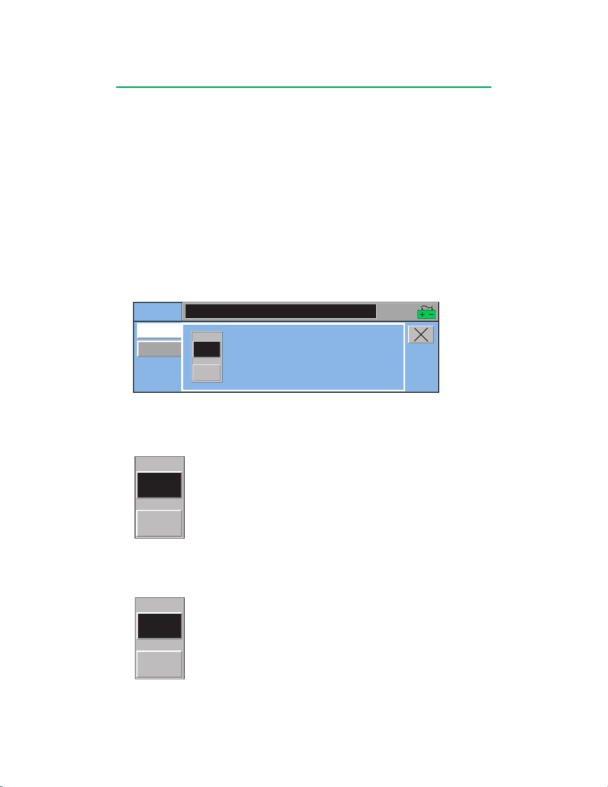
Central Control Monitor
TMR1
Reset
000:08
10:16
TMR1
Reset
000:21
10:16 10:17
Aux
Messages
TMR1
Reset
000:00
Timers
16:07:51
To Reset Auto Dose Selection:
Make sure the cardioplegia pump is stopped or that the Manual button is selected.
Otherwise, the button text will be gray indicating that the Auto Dose value cannot be
reset.
1. Touch the Reset button.
• The value set in the Auto Dose Setup subtab for the selected Auto Dose appears
to the left of the Reset button.
• An additional dose can now be delivered and automatically stop the pump.
Aux Tab
The Aux tab has two subtabs: Timers and Messages.
Timers Subtab
Timers, other than Pump and Clamp, are controlled through the Timers subtab. To
change the start value of a count down timer, use the Timers subtab within the Setup
tab.
To start the timer:
1. Touch the black box.
• The start time appears on the left side of the button.
To stop the timer:
1. Touch the black box again.
• The stop time appears on the right side of the timer display.
To resume the timer:
1. Touch the black box again.
• The timer continues counting.
• The resume time appears on the left side of the button.
4-30
Page 93
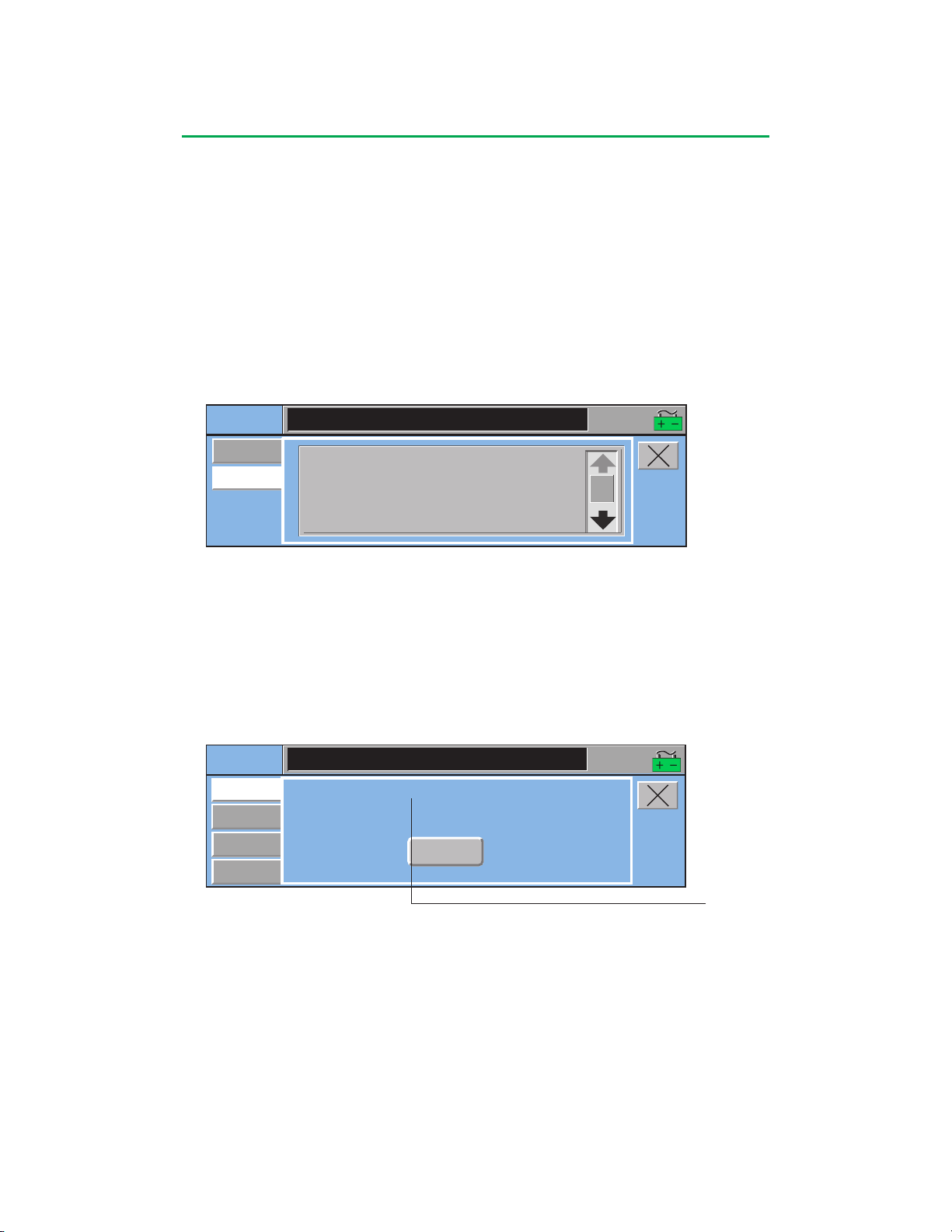
Central Control Monitor
Aux
Timers
Messages
08:45 Air Detected: Arterial STOPPED
08:45 Gas System Warming Up
08:45 Gas Flow: Off
08:28 NO CDI 500 Data
08:28 Calibrate OCCLUDER
16:07:51
System
Power
Settings
Audio Volume:
High
Perfusion Screen Name: CABG Roller
Reassign
Module
Module Info
16:07:51
To reset the timer:
1. Stop the Timer.
2. Touch the Reset button.
• The timer resets to 0.
Messages Subtab
The Messages subtab allows the user to access a list of the system messages that
have occurred during a case, along with the time that they occurred. The messages
are sorted by order of occurrence, with the most recent messages listed first. All
system messages including alarm, alert, error, and status messages appear in this
list. The list is accessible for the duration of the case and is capable of logging up to
3000 messages.
Use the scroll bar to view messages that are beyond the viewing area.
System Tab
The System tab has four subtabs: Settings, Power, Reassign Module, and Module
Info.
Settings Subtab
This subtab allows the user to view the current Perfusion Screen name and adjust the
volume of the audio tone.
Perfusion Screen Name
To Adjust Volume:
Touch the Audio Volume button to toggle through the choices: High,
Medium, Low. Default is High and is reset to High when a Perfusion Screen is
opened.
4-31
Page 94
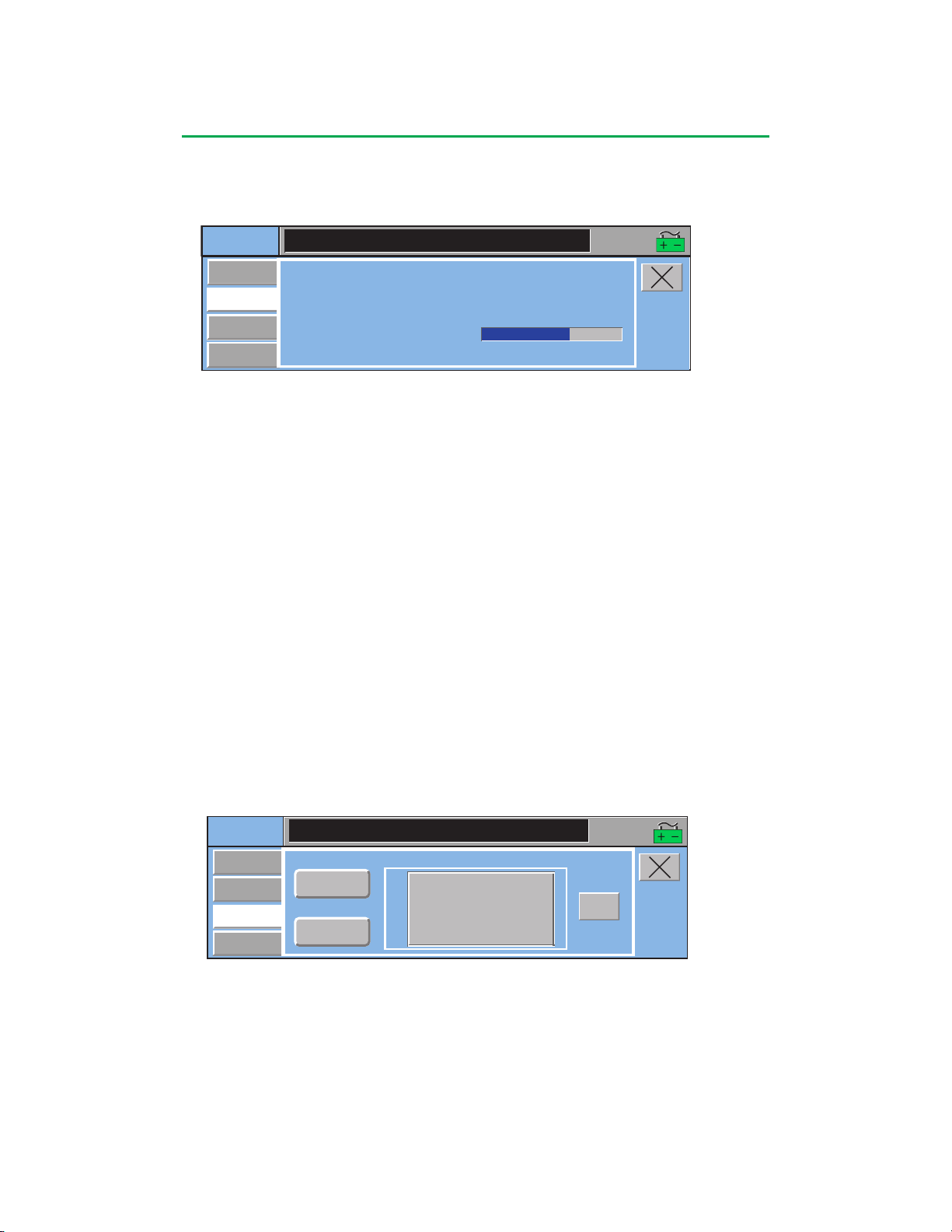
Central Control Monitor
System
Settings
Module Name:
ART Air
Reassign
Module
Module Info
Module Type:
Air Sensor
Power
Select Replacement
Reassign
Module
Reassign
Module
Offline Air Sensor
16:07:51
Power Subtab
This subtab indicates the power sources currently in use, the % of AC power in use,
an estimate of remaining battery time, and a graphical display of battery charge level.
System
Settings
Power
Reassign
Module
Module Info
Power Source: AC Power
AC Power Capacity Used: 11.8 %
Estimated Battery Time Remaining (min): 82
Battery Charge Level:
16:07:51
The Power Source is displayed as AC Power1, Battery, or SYSTEM POWER
SHUTDOWN if the batteries are depleted and the system is about to shutdown
completely. The AC Power Capacity Used is displayed in % if on AC and dashed
out if on battery. This is an indicator of the power consumption. If the system power
need approaches the limit of available power, the message, “Power System at 80%
Capacity” is displayed on the CCM to alert the user.
The Battery Charge Level is displayed as a bar graph to indicate charge status of the
battery.
Reassign Module Subtab
If a pump or module is broken, missing, or not communicating, use the Reassign
Module function to replace the device. A reassigned device takes on the role of the
broken device including icon control from the Perfusion Screen, all alert and alarm
limits, and all safety connections.
Note: When a module/pump has been reassigned, it replaces the original module
only for the duration of the case. If this reassigned module is a permanent
replacement for the original module, it should be assigned to the system from the
Configuration area. If it is not assigned to the screen through the Configuration area,
the device icon will display a “?” each time the Perfusion Screen is opened and the
module will need to be reassigned before it can be used.
1
AC power refers to AC (Mains) power.
4-32
Page 95
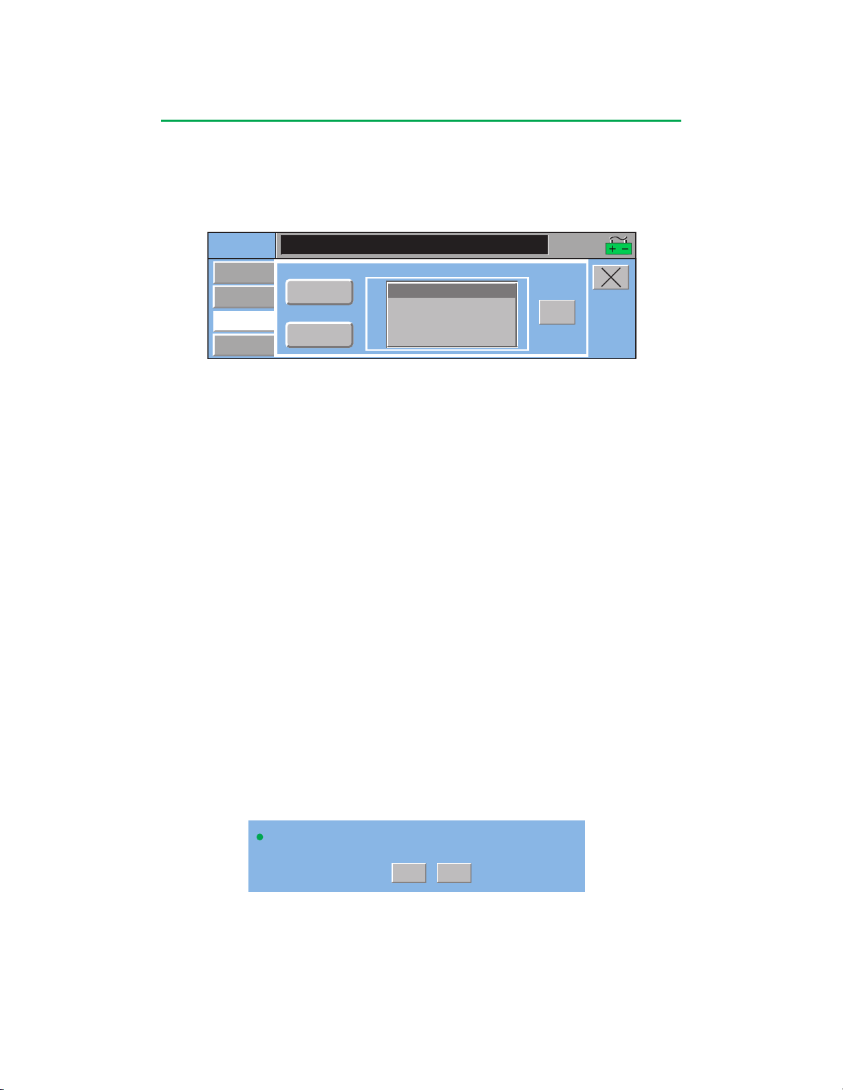
Central Control Monitor
Yes
Pressure Sensor: Reassign CPG Pres to Offline Pressure Sensor?
No
System
Settings
Module Name:
CPG Pres
Reassign
Module
Module Info
Module Type:
Pressure
Sensor
Power
Select Replacement
16:07:51
Reassign
Module
Offline Pressure Sensor
ART Pres / Pres 1
To Reassign a Module:
1. Select the module type by touching the Module Type button to toggle
through the choices until the appropriate device is displayed.
2. Select the module name by touching the Module Name button to toggle
through the choices.
3. Select the replacement module from the list of devices. Offline devices are
on the top of the list followed by online devices which are identified by device
name.
• When reassigning temperature and pressure modules, both channels will be
assigned to the replacement module.
• When reassigning the primary pump, if a backup pump was designated
during configuration, it will automatically be highlighted.
• The primary pump appears on the bottom of the list when reassigning pumps
of that same type.
Note: If an online device is selected as the replacement, confirm that it is
appropriate for reassignment.
• If a primary centrifugal pump is reassigned to a backup roller pump and if
flow has been placed on the centrifugal pump, flow module data will no
longer be displayed, and the backflow alarm and minimum flow alarm are no
longer available. In addition, the centrifugal Coast response becomes a roller
pump Stop response for alarm events and a roller pump Message Only
response for alert events.
4. Verify that the correct module LED, pump module Identification (ID), or pump
name is flashing. When the correct module is flashing, touch the Reassign
Module button. This button is enabled when a selection has been made from
the list.
The system prompts the user to confirm the reassign process. Pump default direction
will change to match the system direction except when the pump is running. If the
pump is running during the reassign process, the pump direction will only change to
match the system direction upon entering a Perfusion Screen or when the system is
restarted.
5. Select Yes to complete the reassignment.
• Do not use the local control panel during reassignment.
• After reassigning modules, ensure that the LED on the reassigned module is
constant green or that the reassigned pump displays the new name.
• If reassigning a Master or Follower pump, re-establish the communications
link between the pumps. Use the Master or Follower Status subtab within the
Pump tab to reconnect the pumps. See Central Control Monitor chapter,
Pump tab, Master and Follower Status subtab section.
4-33
Page 96
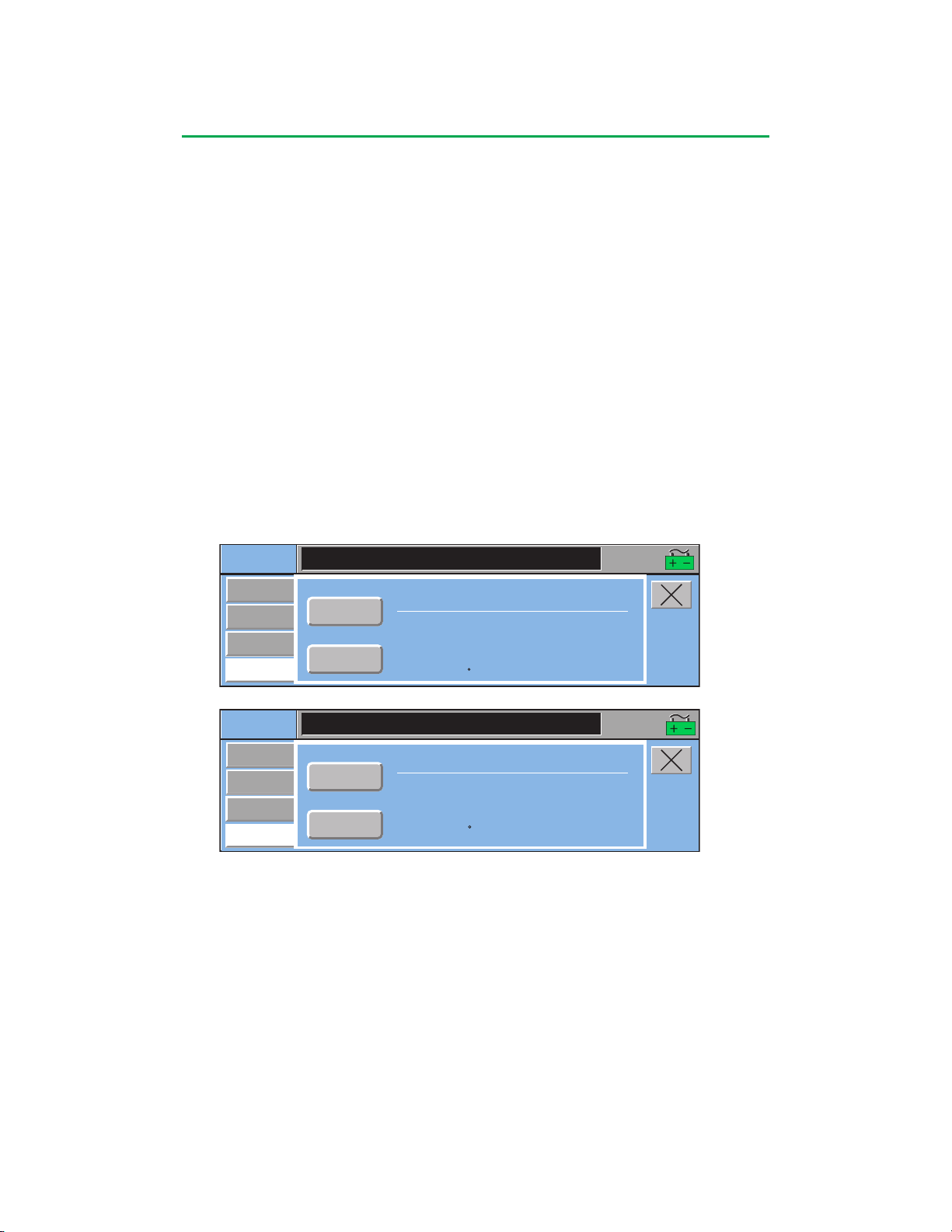
Central Control Monitor
System
Settings
Module Name:
ART Air
Module ID: 00012
Self Test Result: PASS
Reassign
Module
Module Info
Module Type:
Air
Sensor
Power
Software Revision: 1.00
Operation Status: PASS
V5 Voltage (mV): 5084 PASS
V5 Current (mA): 110 PASS
Vmot Voltage (mV): 22915 PASS
Vmot Current (mA):80PASS
Temperature ( C): 37.2 PASS
16:07:51
System
Settings
Module Name:
Arterial
Module ID: 00019
Self Test Result: PASS
Reassign
Module
Module Info
Module Type:
Large Roller Pump
Power
Software Revision: 1.03
Operation Status: PASS
V5 Voltage (mV): 5020 PASS
V5 Current (mA): 293 PASS
Vmot Voltage (mV): 23871 PASS
Vmot Current (mA): 176 PASS
Temperature ( C): 30.0 PASS
Total Volume (mL): 6710
16:07:51
Note: When reassigning pumps, verify all operating parameters after
reassignment, including tube size or flow constant, direction, and display units.
Select No to return to the previous screen.
Module Info Subtab
Information about each module that is online can be displayed using the Module Info
subtab. This information can assist in determining whether operating parameters for
the module or pump are within operating range.
For each online module the following information will be displayed:
Module ID:
Software Revision:
Self Test Result: Pass/Fail
Operation Status: Pass/Fail
V5 Voltage (mV): and Pass/Fail Status
V5 Current (mA): and Pass/Fail Status
Vmot Voltage (mV): if applicable and Pass/Fail Status
Vmot Current (mA): if applicable and Pass/Fail Status
Temperature (degrees C): and Pass/Fail Status
Total Volume (mL): total volume delivered for selected roller pump
A failure of the self test or operational status indicates the module or pump is not
functioning properly and should be replaced. Values not applicable to a specific
device will post an N/A in the Pass/Fail column.
4-34
Page 97
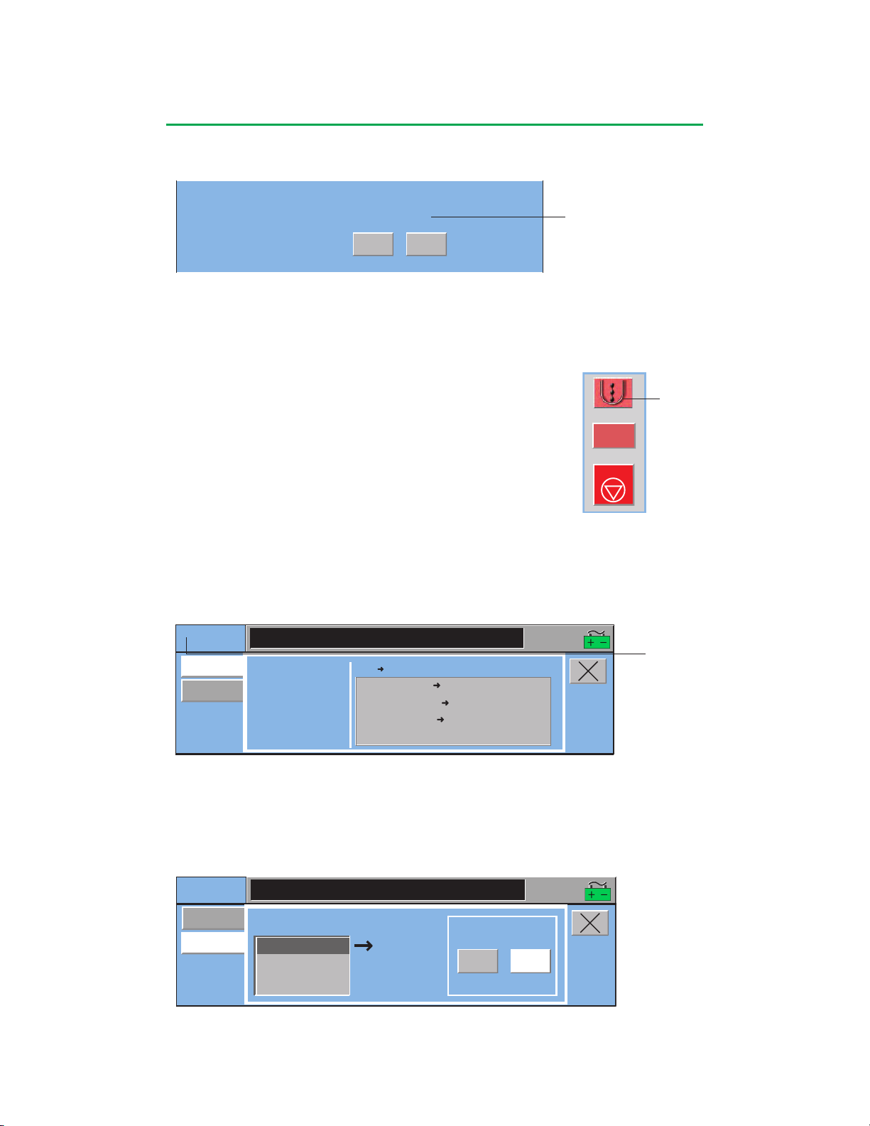
Central Control Monitor
Yes
End this case now?
All pumps will stop.
Gas flow will be turned off.
No
STOP
0.250
L/min
Pump icon
CPG
16:07:51
Summary
Servo
RPM:0 RPM
Direction: Forward
Flow:0.000 L/min
Tube Size:4:1
CPG Pres Pres Alarm Stop: 360 mmHg
Arterial Pump Stop
Stop
CPG Pres Pres Alert
Message Only: 300 mmHg
Event Pump Response:
CPG
16:07:51
Summary
0 mmHg
Servo Control:
Servo
Select Servo Source:
Setpoint:
CPG Pres
Auto
Auto
Manual
Post Case Tab
This tab allows the user to end the case.
To end the case:
Touch the Yes button.
Touch the No button to continue the current case.
Pump Tab
The Pump tab is accessed through the pump icon and is
used to view a summary of pump parameters or initiate Servo
mode and Pulse mode if applicable. For a primary pump, the
master or follower pump has three subtabs: Summary, Servo,
and Master Status or Follower Status. For all other pumps,
the Pump tab has two subtabs: Summary and Servo.
Touch the pump icon to access the Pump tab.
• The pump control box will highlight with a blue perimeter.
Only displayed if a gas blender
is installed
CPG
Summary Subtab
The Summary subtab displays the pump name, the current RPM, direction of flow,
flow in L/min, and the tube size for roller pumps or the minimum flow alarm value for
centrifugal pumps. The configured safety connections are also displayed.
CPG indicates the
name of the pump
Servo Subtab
In Servo mode, the pump speed is automatically regulated to maintain a specific
user selected pressure or flow. During Configuration, a pressure or flow module is
designated as a servo data source. If the servo control source designation is not
enabled, a pump cannot be placed in Servo mode. See Edit Safety Connections
section in this chapter for details on setting the servo source.
The Auto button enables Servo mode. The Manual button in the Servo subtab or
on the pump local control panel disables Servo mode. See the Roller Pumps and
Centrifugal Control Unit chapters for details of servo operation.
4-35
Page 98
Central Control Monitor
Arterial
16:07:51
Summary
Rate:
Pulse Control:
Pulse
100%
Servo
50%
Base:
Width:
Auto
Auto
Manual
60 BPM
85%
50%
Pulse Subtab
The Pulse subtab can be used to adjust pulse parameters and initiate Pulse mode for
a roller pump or centrifugal pump designated as the primary pump.
Roller Pump Pulse Parameters
The Rate, Width, and Base are set up using the Pulse subtab.
To Set the Rate:
1. Touch the Rate button.
2. Use the large arrows to change the Rate in increments of 10 beats per minute.
3. Use the small arrows to change the Rate in increments of 1 beat per minute.
4. Touch the Rate button again to store the new value.
1
To Set the Base:
1. Touch the Base button.
2. Use the large arrows to change the Base in increments of 10%.
3. Use the small arrows to change the Base in increments of 5%.
4. Touch the Base button again to store the new value. The recommended
minimum Base is 30%.
To Set the Width:
1. Touch the Width button.
2. Use the large arrows to change the Width in increments of 10%.
3. Use the small arrows to change the Width in increments of 5%.
4. Touch the Width button again to store the new value. The recommended
minimum Width is 30%.
See the Roller Pumps chapter for details of Pulse mode operation.
1
The use of the term “Pulse mode” refers to the variable pressure and flow
waveforms that result from the cyclic operation of the primary pump. Replication
of a physiologic pulse from a natural heart is not obtained with a pump speed
controller. No claim of clinical benefit from the use of the Pulse mode has been
reviewed by global Regulatory Agencies.
4-36
Page 99
Central Control Monitor
Arterial
Summary
Rate:
Pulse Control:
Pulse
100%
Servo
50%
Base:
Width:
Auto
Auto
Manual
85%
16:07:51
60 BPM
60 BPM
50%
50%
Blood
Summary
Master Status
16:07:51
Servo
Master Pump: Blood
Follower Pump: Cryst
Master-to-Follower Ratio: 4:1
Connect Status: PASS
Cryst
Summary
Follower Status
16:07:51
Servo
Master Pump: Blood
Follower Pump: Cryst
Master-to-Follower Ratio:
%
Connect Status: FAIL
Stop and Reconnect
Centrifugal Pulse Parameters
Rate and Width are fixed and only Base must be set up.
1. Touch the Primary Pump icon to access the Primary Pump tab.
2. Select the Pulse subtab.
To Set the Base
1. Touch the Base button.
2. Use the large arrows to change the Base in increments of 10%.
3. Use the small arrows to change the Base in increments of 5%.
4. Touch the Base button again to store the new value. The recommended
minimum Base is 50%.
See the Centrifugal Control Unit chapter for details of Pulse mode operation.
Master and Follower Status Subtab
The Master and Follower Status subtab is a summary of the master and follower
pump names, the speed or flow ratio setting when the tab was opened, and the
connect status of the pumps.
If the master and follower pumps lose their connection to each other, these pumps
will stop automatically. The connection between these pumps must be reestablished
To reestablish pump connection:
1. Ensure both pumps are stopped.
2. Touch the Stop and Reconnect button.
• If reconnect is successful, the screen will display “Connect Status: PASS”. The
display on each roller pump will indicate “M” or “F”.
4-37
Page 100

Central Control Monitor
Central Control Monitor Messages
The following table includes all the messages that can appear on the CCM display
and corresponding operator responses.
Priority Condition CCM Display Message Operator Response
Alarm Battery is depleted SYSTEM POWER Use manual backup equipment to
and system is shutting SHUTDOWN finish case. Fully recharge battery
down. before using the system again.
Pump goes to 0 flow as < Pump Name >: STOPPED Correct condition.
a result of a Reduce Start pump if stopped.
Speed response to an
alert or alarm.
Pump goes to 0 flow as < Pump Name >: STOPPED Correct the conditions that caused
a result of receiving a the Reduce Speed/Pause responses.
Pause and a Reduce Restart the pump.
Speed response.
Air detected. < ABD Name > : Correct air condition, reset air sensor,
AIR DETECTED restart pump if stopped.
Air detected. AIR DETECTED: Correct air condition, reset air sensor,
< Pump Name > restart pump if stopped.
< Pump Response >
Air sensor on, and < ABD Name > : Reconnect air sensor, reset air
disconnected. AIR DETECTED sensor, restart pump if stopped.
Pressure has risen < Pressure Name > : Correct over pressure condition.
above alarm limit. OVER PRESSURE Start pump if stopped.
Pressure has risen OVER PRESSURE: Correct over pressure condition.
above alarm limit. < Pump Name > Start pump if stopped.
< Pump Response >
Reservoir level below < Level Detector Name > : Fill reservoir to above alarm level.
alarm level. LOW LEVEL Alarm clears automatically.
Restart pump if stopped.
Reservoir level below LOW LEVEL: Fill reservoir to above alarm level.
alarm level. < Pump Name > Alarm clears automatically.
< Pump Response > Restart pump if stopped.
Backflow has been < Flow Sensor Name > : Correct backflow condition.
detected. BACKFLOW Alarm clears automatically.
Restart pump if stopped.
Backflow has been BACKFLOW: Correct backflow condition.
detected. < Pump Name > Alarm clears automatically.
< Pump Response > Restart pump if stopped.
Flow for flow sensor < Pump Name > : Correct low flow condition.
placed on a centrifugal MINIMUM FLOW Alarm clears automatically.
pump has gone below
minimum limit.
4-38
 Loading...