

Page 1

IBUC 2, IBUC 2e, IBUC 2G, and IBUC R
Intelligent Block Upconverter
Operations Manual
24-Hour Technical Support: +1 408.782.2166
Page 2

This document is provided to customers who have purchased Terrasat Communications, Inc.
equipment. This document is copyright protected and no part of this manual may be reproduced,
transcribed, or translated into any language or transmitted in any form whatsoever without the
prior written consent of Terrasat Communications, Inc.
Technical information contained in this publication is for reference purposes only and is subject
to change without notice. Every effort has been made to supply complete and accurate
information; however, Terrasat Communications, Inc. assumes no responsibility and will not be
liable for any errors, omissions, damage, or loss that might result from any use of this manual or
the information contained therein (even if this information is properly followed and problems still
arise).
Part Number: O&M-22062-0001
Revision: F
© December 2015 Terrasat Communications, Inc.
Phone: +1 408.782.5911315 Digital Drive
Morgan Hill, CA 95037 FAX: +1 408.782.5912
www.terrasatinc.com
Page 3

TABLE OF CONTENTS
Preface
Conventions and References .................................................................................................... P-1
Cautions and Warnings ..................................................................................................... P-2
Trademarks........................................................................................................................ P-2
Electrical Safety Notice .................................................................................................... P-2
Chapter 1, Introduction
Block Upconverters.................................................................................................................. 1-1
Reference Documents .............................................................................................................. 1-2
Warranty Information............................................................................................................... 1-4
Export Regulations................................................................................................................... 1-5
Chapter 2, Functional Description
Introduction .............................................................................................................................. 2-1
System Components................................................................................................................. 2-1
DC Supply............................................................................................................................ 2-7
AC Supply............................................................................................................................ 2-9
Fuses..................................................................................................................................... 2-10
Monitor and Control.............................................................................................................2-12
RF Signal Flow .................................................................................................................... 2-12
Software ............................................................................................................................... 2-19
System Configurations......................................................................................................... 2-20
Storage Information .............................................................................................................2-25
Chapter 3, Installation
Introduction .............................................................................................................................. 3-1
General Requirements .............................................................................................................. 3-1
Unpacking ......................................................................................................................... 3-1
Furnished Items.................................................................................................................3-2
Accessories........................................................................................................................ 3-3
Installing the ODU............................................................................................................... 3-4
Test Equipment ................................................................................................................. 3-4
Site Considerations ........................................................................................................... 3-4
Mounting Considerations.................................................................................................. 3-4
Power Requirements ......................................................................................................... 3-5
Grounding .........................................................................................................................3-7
Antenna Recommendations ..............................................................................................3-8
Antenna Mounting ............................................................................................................3-8
System Pressurization ....................................................................................................... 3-12
System Cabling Requirements .......................................................................................... 3-13
i
Page 4

Cable and Waveguide Connections ..................................................................................3-16
Basic System Alignment...................................................................................................... 3-21
Setting the Tx and Rx Frequencies ...................................................................................3-21
Transmit Power Alignment............................................................................................... 3-22
Transmit RF Output Adjustment with Modem or Converter (70 MHz to L-band) .......... 3-23
Final Checks............................................................................................................................. 3-24
Chapter 4, Operations
Introduction .............................................................................................................................. 4-1
Start-up Checklist..................................................................................................................... 4-1
Turning On the IBUC........................................................................................................... 4-2
Setting Operating Parameters............................................................................................... 4-2
Setting the Tx Frequency (L-band) ................................................................................... 4-4
Setting Alarm Thresholds .................................................................................................4-4
Configuring Alarm States .................................................................................................4-5
Configuring ALC/AGC..................................................................................................... 4-5
Configuring the External Mute ......................................................................................... 4-6
Common Errors ........................................................................................................................ 4-7
LED is Red........................................................................................................................ 4-7
No Power to the IBUC 2, IBUC 2e, IBUC 2G, or IBUC R............................................. 4-7
Time Stamp Data is Incorrect ...........................................................................................4-8
Satellite Network Operations Center Doesn’t Recognize Signal...................................... 4-8
Transmit Power in Saturation............................................................................................ 4-9
Tx Input/Output Level Verification .................................................................................. 4-9
Chapter 5, Monitor and Control Features
Introduction .............................................................................................................................. 5-1
M&C Interfaces........................................................................................................................ 5-1
RS232................................................................................................................................... 5-1
Hand-held Terminal ............................................................................................................. 5-2
Multifunction LED...............................................................................................................5-4
Frequency Shift Keying (FSK) Modem Interface................................................................ 5-5
RS485................................................................................................................................... 5-6
ASCII Mode......................................................................................................................5-6
Legacy Binary Mode......................................................................................................... 5-8
Ethernet ................................................................................................................................ 5-9
Determining the IP Address of Your IBUC...................................................................... 5-9
Telnet................................................................................................................................. 5-18
Web Server........................................................................................................................ 5-18
SNMP................................................................................................................................ 5-19
Power Measurement................................................................................................................. 5-21
Chapter 6, Troubleshooting
Maintenance .............................................................................................................................6-1
Transceiver Fault Isolation................................................................................................... 6-1
ii
Page 5

AC Power Problems/Conditioning ....................................................................................6-1
Site-Related Problems .......................................................................................................6-2
M&C Checks .....................................................................................................................6-2
Power Supply Checks........................................................................................................6-3
Transmit Power Setting .....................................................................................................6-3
Common Problems ...............................................................................................................6-5
Tx Output is Disabled........................................................................................................6-5
Incorrect Frequency Settings .............................................................................................6-5
Damaged Cables ................................................................................................................6-5
10 MHz Reference Signal is at the Wrong Level or Missing............................................6-5
Antenna is Pointed Toward Wrong Satellite or is Misaligned ..........................................6-6
Moisture Migrated Into the IBUC .....................................................................................6-6
Bad Orthogonal Mode Transducer and/or Antenna ..........................................................6-7
LED is Red ........................................................................................................................6-7
Repair Policy.............................................................................................................................6-8
Returned Material Authorization (RMA) .............................................................................6-8
Chapter 7, Transmit Redundant Systems
Description................................................................................................................................7-1
Interface for Tx Redundant (1+1) Systems ..........................................................................7-2
Component Descriptions...........................................................................................................7-5
Intelligent Block Upconverter ..............................................................................................7-5
Tx 1+1 Interface Module......................................................................................................7-5
Waveguide Switch................................................................................................................7-6
Software................................................................................................................................7-6
Installation and Setup................................................................................................................7-7
System Cabling Requirements..............................................................................................7-8
Tx 1+1 System...................................................................................................................7-8
Tx 1+1 Interface Module...................................................................................................7-9
Cable and Waveguide Connections......................................................................................7-13
Water-Resistant Wrap........................................................................................................7-13
Typical Initial Setup ..........................................................................................................7-14
Grounding.............................................................................................................................7-14
Tx Redundancy/PSUI Grounding Recommendations.......................................................7-15
System Alignment and Operation.............................................................................................7-16
General..................................................................................................................................7-16
Test Equipment.....................................................................................................................7-16
Setting the Tx Frequencies ...................................................................................................7-17
Tx Power Alignment .........................................................................................................7-17
Final Checks .............................................................................................................................7-18
M&C Setup...........................................................................................................................7-18
Service and Maintenance ..........................................................................................................7-25
Standard Maintenance ..........................................................................................................7-25
Fault Isolation .......................................................................................................................7-25
Common Problems ............................................................................................................7-29
iii
Page 6

M&C Functions.................................................................................................................... 7-30
User Interfaces ..................................................................................................................7-30
Repair Policy ............................................................................................................................ 7-33
Appendix A, Part Numbering Schema
Identifying the Part and Serial Numbers .................................................................................. A-1
Decoding the Part Number....................................................................................................... A-1
Appendix B, Using HyperTerminal
Establishing a HyperTerminal Session .................................................................................... B-1
Using a Saved Connection .......................................................................................................B-7
Ending a HyperTerminal Session............................................................................................. B-8
Appendix C, Web Pages
Introduction .............................................................................................................................. C-1
Screen Shots ............................................................................................................................. C-5
Log In ................................................................................................................................ C-5
Information Tab ................................................................................................................C-6
Alarm Tab ......................................................................................................................... C-8
Sensor Tab......................................................................................................................... C-11
Transmit Configuration Tab.............................................................................................. C-13
Interface Configuration Tab.............................................................................................. C-18
System Configuration Tab ................................................................................................ C-21
Alarm Configuration Tab.................................................................................................. C-23
Redundancy Configuration Tab ........................................................................................ C-26
Alarm Log Tab.................................................................................................................. C-29
Appendix D, Hand-held Terminal Menu Tree
Menu Options........................................................................................................................... D-1
Info & Sensors................................................................................................................... D-5
Tx ...................................................................................................................................... D-5
Alarm................................................................................................................................. D-6
Tx Thresholds.................................................................................................................... D-6
Interface............................................................................................................................. D-6
SNMP................................................................................................................................ D-7
System............................................................................................................................... D-7
Redundancy....................................................................................................................... D-7
Appendix E, Legacy Binary Command Message Structure
Command Set ........................................................................................................................... E-1
Legacy Response Message Structure ....................................................................................... E-3
Data Field Definitions..........................................................................................................E-5
iv
Page 7

Appendix F, ASCII Command/Response Structure
Command Set............................................................................................................................F-1
Common Commands ............................................................................................................F-4
Receive-only Commands......................................................................................................F-20
Transmit-only Commands ....................................................................................................F-27
Redundancy Commands .......................................................................................................F-44
Appendix G, Component Specifications and Reference Drawings
Reference Drawings..................................................................................................................G-1
Data Sheets ...............................................................................................................................G-10
Appendix H, Glossary
Glossary of Terms.....................................................................................................................H-1
Index
v
Page 8

vi
Page 9

LIST OF TABLES
Table P.1 Typographical Conventions ........................................................................................ P-1
Table 1.1 Satellite Operation Standards...................................................................................... 1-2
Table 2.1 IBUC
Table 2.2 IBUC
Table 2.3 IBUC 2G Transmit Frequency Plans.......................................................................... 2-5
Table 2.4 IBUC R Transmit Frequency Plans............................................................................ 2-6
Table 2.5 AC Supply Operating Voltage Ranges ....................................................................... 2-9
Table 2.6 Fuse Markings............................................................................................................. 2-10
Table 2.7 Fuse Markings Explained ........................................................................................... 2-12
Table 2.8 External 10 MHz Reference Signal Parameters.......................................................... 2-13
Table 2.9 Internal 10 MHz Reference Signal Parameters........................................................... 2-13
Table 2.10 Basic System Requirements........................................................................................ 2-20
Table 3.1 Recommended Test Equipment ..................................................................................3-4
Table 3.2 Terrasat Outdoor Power Supplies ...............................................................................3-6
Table 3.3 Interface Connector Schedule ..................................................................................... 3-13
Table 3.4 Pin Assignments for M&C Interface Connector J2 ....................................................3-14
Table 3.5 Pin Assignments for DC Power Connector J3............................................................ 3-15
Table 3.6 Pin Assignments for AC Power Connector J3............................................................ 3-16
Table 3.7 Pin Assignments for Ethernet Connector J4 ............................................................... 3-16
Table 5.1 Default Alarm Configuration ...................................................................................... 5-4
Table 5.2 Transmitter Link Specifications.................................................................................. 5-5
Table 5.3 Receiver Link Specifications ......................................................................................5-5
Table 5.4 ASCII Mode Command Format.................................................................................. 5-7
Table 5.5 Packet Format ............................................................................................................. 5-8
Table 5.6 Data Packet Byte Configuration ................................................................................. 5-8
Table 6.1 Possible Scenarios for IBUCs with an External 10 MHz Reference Signal ............... 6-6
Table 7.1 Tx 1+1 Interface Module Connector Schedule ........................................................... 7-9
Table 7.2 Pin Assignments for M&C Interface Connectors J1, J2, and J3................................. 7-10
Table 7.3 Pin Assignments for M&C Interface Connectors J4 and J6 ....................................... 7-11
Table 7.4 Pin Assignments for M&C Interface Connector J5, J7, J8, and J10........................... 7-11
Table 7.5 Pin Assignments for M&C Interface Connector J9 ....................................................7-12
Table 7.6 Pin Assignments for M&C Interface Connector J11 ..................................................7-13
Table 7.7 Recommended Test Equipment ..................................................................................7-16
Table C.1 Default Values for Power Monitor Frequency............................................................ C-14
Table C.2 Default Values for the Burst Threshold ...................................................................... C-15
Table E.1 Commands .................................................................................................................. E-1
Table E.2 Response to Commands 0x01, 0x02, 0x03, 0x04, 0x08, and 0xFF............................ E-3
Table E.3 Response to IBUC Commands 0x05 and 0x06
(When Data Byte 1 of Command Message = 0x00) ................................................... E-3
2 Transmit Frequency Plans ............................................................................. 2-3
2e Transmit Frequency Plans ........................................................................... 2-4
vii
Page 10

Table E.4 Response to IBUC Command 0x06
(When Data Byte 1 of Command Message = 0x01) ................................................... E-4
Table E.5 Response to IBUC Command 0x07 ............................................................................ E-4
Table E.6 Response to IBUC Command 0x09 ............................................................................ E-5
Table E.7 Data Field Definitions .................................................................................................E-5
Table F.1 Alarm Mask................................................................................................................. F-1
Table F.2 Alarm Flags................................................................................................................. F-2
Table F.3 Error Response Table.................................................................................................. F-3
Table F.4 Default Values for the TAH, TAL, and TBT Commands ..........................................F-34
Table F.5 Default Values for the TFR Command .......................................................................F-38
viii
Page 11

LIST OF FIGURES
Figure 2.1 Front Panel of a DC-powered IBUC 2....................................................................... 2-8
Figure 2.2 Front Panel of a Low Energy Consumption IBUC 2e ............................................... 2-9
Figure 2.3 Front Panel of an AC-powered IBUC
Figure 2.4 DC-powered IBUC Block Diagram........................................................................... 2-16
Figure 2.5 AC-powered IBUC Block Diagram........................................................................... 2-17
Figure 2.6 IBUC 2e Block Diagram (for DC-powered low energy-consumption systems) ....... 2-18
Figure 2.7 DC Power System Configuration............................................................................... 2-22
Figure 2.8 DC Power System Configuration with IFU ............................................................... 2-23
Figure 2.9 AC Power System Configuration............................................................................... 2-24
Figure 3.1 Contents of an IBUC
Figure 3.2 IBUC 2 Field Installation........................................................................................... 3-9
Figure 3.3 IBUC 2 Installation .................................................................................................... 3-10
Figure 3.4 Location of Mounting Holes ...................................................................................... 3-11
Figure 3.5 Location of Adjustment Slots on Optional Mounting Bracket .................................. 3-12
Figure 3.6 Applying the Anti-Seize Lubricant............................................................................ 3-18
Figure 3.7 Waveguide Label and Channel for Gasket ................................................................ 3-19
Figure 5.1 Hand-held Terminal ................................................................................................... 5-3
Figure 5.2 Download Wireshark Icon ......................................................................................... 5-10
Figure 5.3 Wireshark Release Version........................................................................................ 5-10
Figure 5.4 Executable Alert Message.......................................................................................... 5-11
Figure 5.5 Open File Security Warning Message ....................................................................... 5-11
Figure 5.6 Installation Wizard Welcome..................................................................................... 5-12
Figure 5.7 Wireshark License Agreement................................................................................... 5-12
Figure 5.8 Choosing Wireshark Components ............................................................................. 5-13
Figure 5.9 Selecting Additional Wireshark Tasks....................................................................... 5-13
Figure 5.10 Choosing the Installation Location ............................................................................ 5-14
Figure 5.11 Installing WinPcap..................................................................................................... 5-14
Figure 5.12 Installation Progress Bar ............................................................................................ 5-15
Figure 5.13 WinPcap Installer....................................................................................................... 5-15
Figure 5.14 Setup Completion Notification .................................................................................. 5-16
Figure 5.15 Finishing Setup of Wireshark .................................................................................... 5-16
Figure 5.16 Wireshark Menu......................................................................................................... 5-17
Figure 5.17 Selecting An Interface................................................................................................ 5-17
Figure 5.18 Returning IP Address Information............................................................................. 5-18
Figure 7.1 Transmit Redundant System Setup............................................................................ 7-2
Figure 7.2 IBUC
Figure 7.3 Tx 1+1 Interface Module Block Diagram.................................................................. 7-6
Figure 7.4 Tx 1+1 Interface Module Top View .......................................................................... 7-9
Figure 7.5 Multifunction LEDs for a Tx 1+1 System ................................................................. 7-24
Figure 7.6 Hand-Held Terminal .................................................................................................. 7-31
2 Redundant System Diagram ......................................................................... 7-4
2 Shipping Carton ................................................................... 3-3
2..................................................................... 2-10
ix
Page 12

Figure A.1 Identifying the Part and Serial Numbers.................................................................... A-1
Figure A.2 Part Numbering Schema for IBUC G, IBUC 2, IBUC 2e, IBUC 2G, IBUC R....... A-2
Figure A.3 Part Numbering Schema for IBUC............................................................................ A-3
Figure A.4 Part Numbering Schema for Transmit Redundant (Tx 1+1) Systems....................... A-4
Figure A.5 Part Numbering Schema for Receive Redundant (Rx 1+1) Systems ........................ A-5
Figure A.6 Part Numbering Schema for IBUC with PSUI Systems............................................ A-6
Figure A.7 Part Numbering Schema for IFU Systems................................................................. A-7
Figure A.8 Part Numbering Schema for LNBs............................................................................ A-8
Figure A.9 Part Numbering Schema for SSPAs .......................................................................... A-9
Figure A.10 Part Numbering Schema for Redundant SSPA 1+1 Systems.................................... A-10
Figure B.1 New Connection Description Window ...................................................................... B-2
Figure B.2 Connect To Window .................................................................................................. B-3
Figure B.3 COM1 Properties Window......................................................................................... B-4
Figure B.4 Invalid Password Error Message................................................................................ B-5
Figure B.5 ASCII Setup Window ................................................................................................ B-5
Figure B.6 Invalid Value Error Message ..................................................................................... B-6
Figure B.7 Active HyperTerminal Window................................................................................. B-7
Figure C.1 Choosing Network Connections ................................................................................ C-2
Figure C.2 Choosing the Internet Protocol (TCP/IP) Properties.................................................. C-2
Figure C.3 Typing the IP Address................................................................................................ C-3
Figure C.4 Invalid Subnet Mask Error Message.......................................................................... C-4
Figure C.5 Login .......................................................................................................................... C-5
Figure C.6 Information Tab ......................................................................................................... C-6
Figure C.7 Alarm Status Tab ....................................................................................................... C-8
Figure C.8 Sensor Tab ................................................................................................................. C-11
Figure C.9 Tx Configuration Tab ................................................................................................ C-13
Figure C.10 Interface Configuration Tab....................................................................................... C-18
Figure C.11 System Configuration Tab ......................................................................................... C-21
Figure C.12 Alarm Configuration Tab........................................................................................... C-23
Figure C.13 Redundancy Configuration Tab ................................................................................. C-26
Figure C.14 Alarm Log Tab........................................................................................................... C-29
Figure D.1 Sample HHT Display ................................................................................................. D-2
Figure D.2 Sample Info & Sensors Menu .................................................................................... D-2
Figure D.3 Hand-held Terminal Menu Tree ................................................................................ D-4
Figure G.1 Fabrication Drawing, FBD-21012-XXXX, Rev A.................................................... G-2
Figure G.2 Fabrication Drawing, FBD-21984-XXXX, Rev B, page 1 of 2 ................................ G-3
Figure G.3 Fabrication Drawing, FBD-21984-XXXX, Rev B, page 2 of 2 ................................ G-4
Figure G.4 Fabrication Drawing, FBD-20351-0001, Rev A ....................................................... G-5
Figure G.5 Fabrication Drawing, FBD-20606-XXXX, Rev A.................................................... G-6
Figure G.6 Example Installation Drawing for Antenna Mounting, 339-44001-XXXX,
Rev A, page 1 of 2 ..................................................................................................... G-7
Figure G.7 Example Installation Drawing for Antenna Mounting, 339-44001-XXXX,
Rev A, page 2 of 2 ..................................................................................................... G-8
Figure G.8 Example Installation Drawing, IND-10521-0011, Rev A ......................................... G-9
x
Page 13

REVISION HISTORY
Revision Date Description
A February 2013 Initial Release
B February 2013
C February 2013
D May 2013 • Added Chapter 7, Transmit Redundant Systems
E January 2014
F August 2015
• Corrected values for the TFB command in Appendix F
• Updated information about transmit frequency plans in Table 2.1
• Corrected part numbering values in Figure A.2
• Revised information in Chapter 5 about how to determine your unit’s IP address when
it is not on the same subnet as your host computer
• Added the CFD and TTT commands
• Updated list of reference documents in Chapter 1, Introduction
• Updated specifications to include low-energy-consumption units
• Updated data sheets in Appendix G, Component Specifications and Reference
Drawings
• Added the BRM and CBT commands
• Updated fuse markings in Table 2.6
• Attenuation is now 30 dB
• Added information about warm standby mode in Chapter 7, Transmit Redundant
Systems
• Updated part numbers in Appendix A, Part Numbering Schema
• Updated data sheets in Appendix G, Component Specifications and Reference
Drawings
• Added information about the Burst Timeout option in Appendix C, Web Pages and
Appendix D, Hand-held Terminal Menu Tree
xi
Page 14

xii
Page 15

This manual provides information about the Terrasat Communications, Inc. line of
intelligent block upconverters and transmit redundant systems.
Conventions and References
Before you start using this manual, it is important to understand the typographical
conventions and terms used in the documentation.
Table P.1 describes typographical conventions used in Terrasat Communications, Inc.
documentation. For definitions of specialized terms used in the documentation, see
Appendix H, Glossary.
P REFACE
Table P.1
Convention Description/Example
Emphasis
Internal cross-references
Product and feature
names
Technical Publication
Re
ferences
User-entered values
Typographical Conventions
Used to emphasize the importance of a point.
The IP Address must be
References to a section in the same document are marked in blue and
are hyperlinked.
See Warranty Information on page 1-4.
Named Terrasat products and features are identified on first use.
...line of intelligent block upconverters (IBUCs).
References to other Terrasat publications. If the reference is hyperlinked,
it is also underscored.
For detailed information, see the Terrasat Communications, Inc. IBUC
Operations Manual.
A special font marks text that you type.
At the password prompt, type
a unique number.
MyPassword.
Page 16
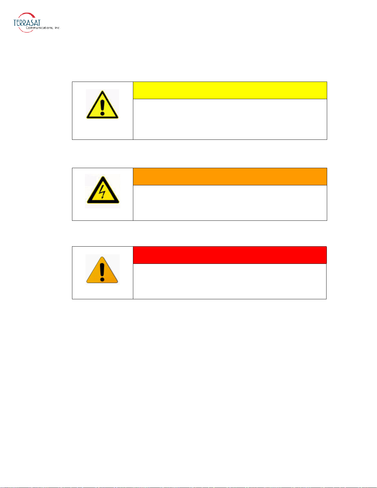
Cautions and Warnings
CAUTION indicates a hazardous situation that, if not
avoided, could result in minor or moderate injury.
CAUTION might also be used to indicate other unsafe
practices or risks of property damage.
HIGH VOLTAGE indicates the presence of a
high-voltage hazard.
CAUTION
HIGH VOLTAGE
WARNING
WARNING indicates a potentially hazardous situation
that, if not avoided, could result in death or serious
injury.
T rademarks
Other product names mentioned in this manual may be trademarks or registered
trademarks of their respective companies and are hereby acknowledged.
Electrical Safety Notice
This equipment has been designed to minimize exposure of personnel to hazards. All
operators and technicians must
• Know how to work around, with, and on high-voltage equipment.
• Exercise every precaution to ensure safety of personnel.
• Exercise extreme care when working near high voltages.
• Be familiar with the warnings in this manual.
P-2 | Preface
Page 17

C HAPTER
C
HAPTER
1
I
NTRODUCTION
This manual is intended for users of Terrasat Communications, Inc. block upconverter
systems including the IBUC
contains information about
• Installation, operation, and maintenance of IBUC 2, IBUC 2e, IBUC 2G, and
IBUC R systems
• Use of user interface protocols for remote monitor and control capabilities
2, the IBUC 2e, the IBUC 2G, and the IBUC R. It
Block Upconverters
The term “intelligent” block upconverter (IBUC) refers to the advanced features and
monitor and control capabilities of the entire line of Terrasat IBUC models. Each
IBUC model includes automatic gain control (AGC) and automatic level control
(ALC) features as well as internal diagnostics. Terrasat IBUCs also provide extensive
monitoring and control through a menu of software commands and alarms providing
access to the numerous operating parameters and features available in the unit. Access
to features and monitor and control (M&C) functions is provided via several methods
including a hand-held terminal, RS232, RS485, TCP/IP (Telnet, HTTP), UDP
(SNMP) and FSK (frequency shift keying) link via the IFL cable. Each IBUC model is
also fitted with a multifunction LED for visual status indications.
Page 18

Reference Documents
Use the satellite operation standards listed in Table 1.1 as reference documents.
Table 1.1
Satellite Operation Standards
Earth Station Standards
Intelsat IESS 308/309
Eutelsat EESS 502
ETS 300-332
ETS 300-159
ETS 300-160
ETSI EN 301 427
ETSI EN 301 428
ETSI EN 301 430
ETSI EN 301 443
MIL-STD-188-164A
with Change 3
MIL-STD 810F
ANSI/TIA/EIA 568 Commercial Building Telecommunications Cabling Standard
Performance Characteristics for Intermediate Data Rate Digital
Carriers Using Convolutional Encoding and QPSK Modulation
Minimum Technical and Operational Requirements for Earth Stations
Transmitting to a Eutelsat Transponder for Non-Standard Structured
Types of SMS Transmissions. Standard M.
Satellite Earth Stations (SES); Transmit-only or transmit-and-receive
very small aperture terminals (VSATs) used for communications
operating in the fixed satellite service (FSS) 6 GHz and 4 GHz
frequency bands.
Satellite Earth Stations (SES); Transmit/receive very small aperture
terminals (VSATs) used for data communications operating in the
fixed satellite service (FFS) 11/12/14 GHz frequency bands.
Satellite Earth Stations (SES); Control and monitoring functions for
very small aperture terminals (VSAT) networks.
Satellite Earth Stations and Systems (SES); Harmonized EN for Low
Data Rate Mobile Satellite Earth Stations (MESs) except aeronautical
mobile satellite earth stations, operating in the 11/12/14 GHz
frequency bands covering essential requirements under article 3.2 of
the Radio & Telecommunications Terminal Equipment (R&TTE)
directive
Satellite Earth Stations and Systems (SES); Harmonized EN for Very
Small Aperture Terminal (VSAT); Transmit-only, transmit/receive, or
receive-only satellite earth stations operating in the 11/12/14 GHz
frequency bands covering essential requirements under article 3.2 of
the Radio & Telecommunications Terminal Equipment (R&TTE)
Directive.
Satellite Earth Stations and Systems (SES); Harmonized EN for
Satellite News Gathering Transportable Earth Stations (SNG TES)
operating in the 11-12/13-14 GHz frequency bands covering essential
requirements under article 3.2 of the R&TTE directive
Satellite Earth Stations and Systems (SES); Harmonized EN for Very
Small Aperture Terminal (VSAT); Transmit-only, transmit/receive, or
receive-only satellite earth stations operating in the 4 GHz and 6 GHz
frequency bands covering essential requirements under article 3.2 of
the R&TTE Directive.
Interoperability of SHF Satellite Communications Terminals for
tactical and long-haul communications.
Materiel acquisition program planning and engineering direction for
considering the influences that environmental stresses have on
materiel throughout all phases of its service life.
1-2 | IBUC 2, IBUC 2e, IBUC 2G, IBUC R Operations Manual: Introduction
Page 19
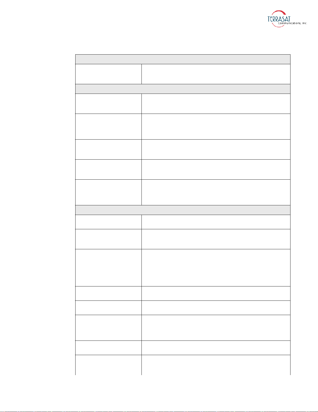
Table 1.1
Satellite Operation Standards (Continued)
Earth Station Standards
ETS 300 019-1-1
Environmental Standards
ETS 300 019-1-2
ETS 300 019-1-4
ETS 300 019-2-1
ETS 300 019-2-2
ETS 300 019-2-4
Equipment Engineering (EE): Environmental Conditions and
Environmental Tests for Telecommunications Equipment. Part 1-1:
Classification of environmental conditions. Storage.
Equipment Engineering (EE): Environmental Conditions and
Environmental Tests for Telecommunications Equipment. Part 1-2:
Classification of environmental conditions. Transportation.
Equipment Engineering (EE): Environmental Conditions and
Environmental Tests for Telecommunications Equipment. Part 1-4:
Classification of environmental conditions. Stationary use at nonweather protected locations.
Equipment Engineering (EE): Environmental Conditions and
Environmental Tests for Telecommunications Equipment. Part 2-1:
Specification of environmental tests; Storage
Equipment Engineering (EE): Environmental Conditions and
Environmental Tests for Telecommunications Equipment. Part 2.2:
Specification of environmental tests; Transportation
Equipment Engineering (EE): Environmental Conditions and
Environmental Tests for Telecommunications Equipment. Part 2-4:
Specification of environmental tests; Stationary use at non-weather
protected locations
EMC/EMI Standards
99/5/EEC
ETSI EN 301 489-1 v1.8.1
ETSI EN 301 489-12 v2.2.2
EN 55022A
EN 61000-3-2
EN 61000-3-3
EN 61000-4-2
EN 61000-4-3
The Radio and Telecommunications Terminal Equipment Directive
(R&TTE)
Electromagnetic Compatibility and Radio Spectrum Matters (ERM);
Electromagnetic Compatibility (EMC) standard for radio equipment
and services; Part 1: Common technical requirements
Electromagnetic Compatibility and Radio Spectrum Matters (ERM);
Electromagnetic Compatibility (EMC) standard for radio equipment
and services; Part 12: Specific conditions for Very Small Aperture
Terminal, Satellite Interactive Earth Stations operated in the
frequency ranges from 4 GHz through 30 GHz in the Fixed Satellite
Services (FSS)
Information Technology Equipment – Radio Disturbance
Characteristics – Limits and methods of measurement
Electromagnetic Compatibility (EMC) – Part 3.2: Limits for harmonic
current emissions (equipment input current < 16 A per phase)
Electromagnetic Compatibility (EMC) – Part 3.3: Limitation of voltage
changes, voltage fluctuations, and flicker in public low-voltage supply
systems for equipment with rated current ≤ 16 A per phase and not
subject to conditional connection
Electromagnetic Compatibility (EMC) – Part 4-2: Testing and
measurement techniques – Electrostatic discharge immunity test
Electromagnetic Compatibility (EMC) – Part 4-3: Testing and
measurement techniques – Radiated, radio-frequency,
electromagnetic field immunity test
Reference Documents | 1-3
Page 20
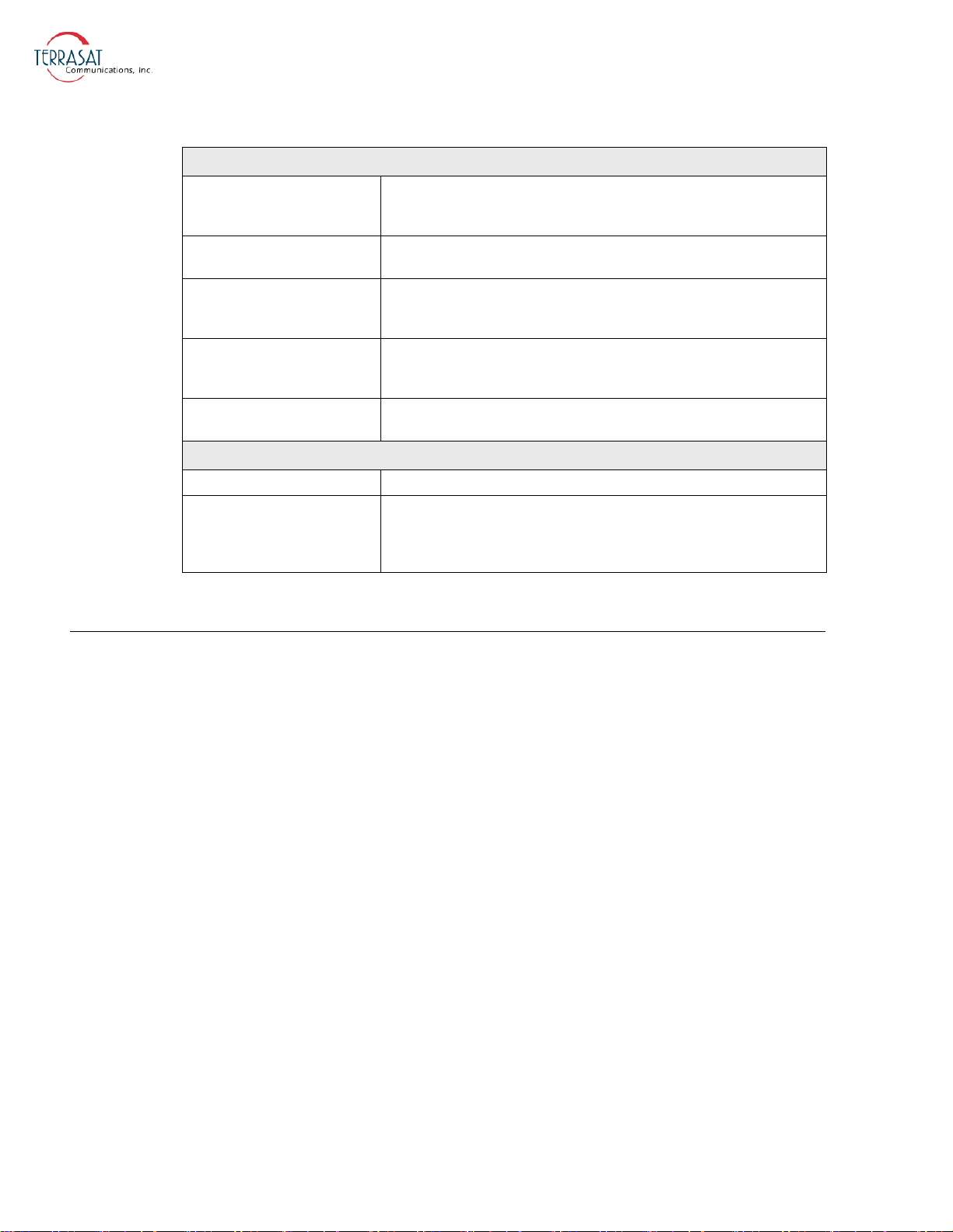
Table 1.1
EMC/EMI Standards
EN 61000-4-4
EN 61000-4-5
EN 61000-4-6
EN 61000-4-11
MIL-STD-461E
Safety Standards
2006/95/EC The Low Voltage Directive (supersedes 73/23/EEC)
EN 60950-1
Satellite Operation Standards (Continued)
Electromagnetic Compatibility (EMC) – Part 4-4: Testing and
measurement techniques – Electrical fast transient/burst immunity
test
Electromagnetic Compatibility (EMC) – Part 4-5: Testing and
measurement techniques – Surge immunity test
Electromagnetic Compatibility (EMC) – Part 4-6: Testing and
measurement techniques – Immunity to conducted disturbances,
induced by radio-frequency fields
Electromagnetic Compatibility (EMC) – Part 4-11: Testing and
measurement techniques – Voltage dips, short interruptions, and
voltage variations immunity tests
Requirements for the Control of Electromagnetic Interference
Characteristics of Subsystems and Equipment
Information technology equipment – Safety as applied to
mains-powered or battery-powered information technology
equipment, including electrical business equipment and associated
equipment, with a rated voltage not exceeding 600
V.
W arranty Information
Determination of warranty status of equipment shall be in accordance with the
following Terrasat Communications, Inc. Warranty Policy.
(A) This warranty is for equipment of Terrasat Communications, Inc. The term
“Terrasat” as used throughout this warranty shall mean Terrasat Communications,
Inc., if the equipment was manufactured by Terrasat Communications, Inc.
(B) Terrasat warrants that its equipment shall be free from defects in material or
workmanship at the time of shipment and that it will conform to applicable
specifications.
For all Satcom products, the buyer shall exercise any and all warranty claims within a
period of twenty-four (24) months.
(1) The warranty does not apply to any part of a product if it has been altered,
repaired, or misused in any way that, in the opinion of Terrasat, affects the
reliability of, or detracts from the performance of, any part of the product; or it is
damaged as a result of the use of such part in or in connection with equipment not
previously approved by Terrasat.
(2) The warranty does not apply to any product or parts thereof if its serial number
or the serial number of any of its parts has been altered, defaced, or removed.
1-4 | IBUC 2, IBUC 2e, IBUC 2G, IBUC R Operations Manual: Introduction
Page 21

(3) The warranty does not cover damages or losses incurred in transport.
(4) The warranty does not cover replacement or repair necessitated by loss or
damage resulting from cases beyond the control of Terrasat.
(5) The warranty does not include the furnishing of any labor involved or
connected with the removal and/or reinstallation of warranted equipment or parts
on site, or any labor required to diagnose the necessity for replacement or repair.
(6) In no event shall Terrasat be liable to buyer for any indirect, special, or
consequential damages or lost profits arising from the use of the equipment or
products, even if Terrasat has been advised of the possibility thereof, or for any
inability to use them either separated from or in combination with any other
equipment or products.
(C) Terrasat’s warranty, as stated herein, is in lieu of all other warranties, expressed,
implied or statutory, including those of merchantability and fitness for a particular
purpose, and Terrasat neither assumes nor authorizes any person to assume for it any
other obligation or liability to any person in connection with the sale or use of
Terrasat’s products. The buyer shall pass on to any purchaser, lessee, or other user of
Terrasat’s products, the aforementioned warranty and shall indemnify and hold upon
allegations that the buyer, its agents, or employees have made additional warranties or
representations as to product preference or use.
(D) A fixed charge established for each product will be imposed for all equipment
returned for warranty repair and where the cause of failure cannot be identified by
Terrasat.
Note:
Warranty seals are designed to break upon internal access. Access to the internal
electronic components without prior written approval will void the warranty.
For more information about returning a product for repair, see Repair Policy on
page 6-8.
Export Regulations
Under the Arms Export Control Act (AECA), 22 U.S.C. § 2778 (1994), the United
States Department of State, Directorate of Defense Trade Controls (DDTC),
implements the International Traffic In Arm Regulations (ITAR), 22 C.F.R.
§§ 120-130, which control the export of defense articles and services from the United
States to foreign destinations and persons.
Terrasat X-band IBUC products are subject to ITAR regulations administered by the
U.S. State Department. Section 121.1 of the ITAR is the United States Munitions List
(USML) and includes the commodities, related technical data, and defense services
controlled for export purposes. The X-band IBUC is classified as USML Category
XI(a)(5) “Command, control and communications systems to include radios
Export Regulations | 1-5
Page 22

(transceivers), navigation, and identification equipment.” As indicated in the ITAR,
items in this category are also designated “Significant Military Equipment (SME).”
These products are not considered dual use as defined by the U.S. Commerce
Department.
As ITAR-controlled items that are designated SME, each license application must be
accompanied by Form DSP-83 identifying the end user and intermediate consignees.
In addition, Exporters must ascertain the specific end user and end use prior to
submitting a license application to the Directorate of Defense Trade Controls. Terrasat
normally requests a separate letter to accompany the DSP-83 stating the type of
terminal in which the IBUC will be used and the satellite system over which it will
transmit.
Further, it is required that we inform the end user of the requirements of ITAR section
123.9, as follows:
The written approval of the Directorate of Defense Trade Controls must
be obtained before reselling, transferring, transshipping, or disposing of a
defense article to any end user, end use, or destination other than as stated
on the export license.
Details of ITAR requirements can be found at the U.S. State Department Web site at
http://www.pmddtc.state.gov.
1-6 | IBUC 2, IBUC 2e, IBUC 2G, IBUC R Operations Manual: Introduction
Page 23

The Terrasat outdoor unit (ODU) consists of an intelligent block upconverter (IBUC 2,
IBUC 2e, IBUC 2G, or IBUC R), power supply unit (PSUI), and low-noise block
converter (LNB) for use in satellite earth stations. The outdoor equipment is designed
to interface directly with an L-band satellite modem.
Introduction
C
HAPTER
2
F
UNCTIONAL
C HAPTER
D
ESCRIPTION
This chapter contains detailed information about the various system components of the
following IBUC models:
•IBUC 2: All of the original features of the IBUC but in a smaller, more
cost-effective package that is ideal for applications where compact size, light
weight, and low thermal dissipation are critical factors.
•IBUC 2e: The low energy consumption model of the IBUC 2, intended for use
with modems with limited capacity power supplies and where DC power is
supplied only via coaxial cable.
•IBUC 2G: The compact physical size of the IBUC 2 powered by gallium nitride
(GaN) technology. GaN devices like the IBUC
temperatures and work at much higher voltages than GaAs devices.
•IBUC R: All of the original features of the larger IBUC package with an RJ45
Ethernet connector.
System Components
The interfacility link (IFL) between the ODUs and the L-band modem uses
950 MHz to 2.0 GHz (L-band) as the interface frequency. This approach enables
transmission and reception over the entire satellite band as opposed to a single
transponder. The L-band IFL can also carry associated signals such as 10
voltage, or FSK which simplify installation and reduce costs. Terrasat IBUC systems
2G can operate at much higher
MHz, DC
Introduction | 2-1
Page 24

can be used for single channel per carrier/multiple channels per carrier (SCPC/
MCPC), point-to-point, or point-to-multiple point network applications (such as voice,
data, video, or IP services). The integrated RJ-45 J4 connector enables TelNet, SNMP,
and the embedded Web pages for monitor and control purposes. Its smaller form
factor and lighter weight make the IBUC 2, IBUC 2e, and IBUC 2G ideal for
situations where mobility is key. These smaller models can be carried in a backpack or
case or mounted on antennas that can be quickly assembled and disassembled. See
Figure 2.7 on page 2-22 through Figure 2.9 on page 2-24 for typical equipment
configurations.
The IBUC 2, IBUC 2e, IBUC 2G, and IBUC R are available in a variety of frequency
bands as listed in Table 2.1 through Table 2.4. The IBUC houses the IF interface
(de-mux), the upconverter, the monitor and control (M&C) card, a DC-to-DC
converter (if DC powered) and associated circuitry, an AC-to-DC converter (if AC
powered), and a solid state power amplifier (SSPA) assembly. The IBUC can also
house an optional internal 10 MHz reference signal module. Higher-power IBUCs
also have an external cooling fan assembly. The input interface to the IBUC connects
to a 50 or an optional 75 coaxial cable that carries the L-band transmit signal, and
can carry the external 10 MHz reference oscillator signal, DC power, and bidirectional
M&C FSK signals.
2-2 | IBUC 2, IBUC 2e, IBUC 2G, IBUC R Operations Manual: Functional Description
Page 25
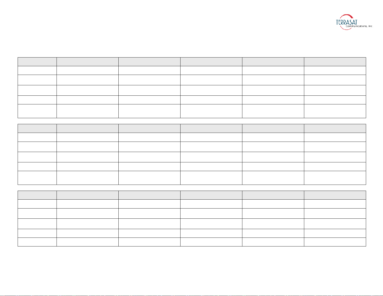
Table 2.1
IBUC 2 Transmit Frequency Plans
Signal Standard C-band Palapa C-band Insat C-band Extended C-band Full C-band
L-band
LO frequency
(Inverting)
LO frequency
(Noninverting)
RF frequency
Output Power
950 MHz to 1525 MHz 975 MHz to 1275 MHz 1150 MHz to 1450 MHz 950 MHz to 1750 MHz 975 MHz to 1850 MHz
7.375 GHz 7.700 GHz 8.175 GHz 7.600 GHz 7.700 GHz
4900 Mhz — — 4900 Mhz 4900 Mhz
5.850 GHz to 6.425 GHz 6.425 GHz to 6.725 GHz 6.725 GHz to 7.025 GHz 5.850 GHz to 6.650 GHz 5.850 GHz to 6.725 GHz
5, 10, 15, 20, 25, 30, 40, 50,
60
watts
5, 10, 15, 20, 25, 30, 40, 50,
60
watts
5, 10, 15, 20, 25, 30, 40, 50,
60
watts
5, 10, 15, 20, 25, 30, 40, 50,
60
watts
5, 10, 15, 20, 25, 30, 40, 50,
60
watts
Signal X-band Standard Ku-band (Band 1) Full Ku-band (Band 2) Low Ku-band (Band 3) DBS-band (Band 1)
L-band
LO frequency
(Inverting)
LO frequency
(Noninverting)
RF frequency
Output Power
950 MHz to 1450 MHz 950 MHz to 1450 MHz 950 MHz to 1700 MHz 950 MHz to 1450 MHz 950 MHz to 1750 MHz
— — — — —
6.950 GHz 13.050 GHz 12.800 GHz 11.800 GHz 16.350 GHz
7.900 GHz to 8.400 GHz 14.000 GHz to 14.500 GHz 13.750 GHz to 14.500 GHz 12.750 GHz to 13.250 GHz 17.300 GHz to 18.100 GHz
5, 10, 20, 25, 40, 50, 60 watts
4, 8, 12, 16, 20, 25, 30,
40
watts
4, 8, 12, 16, 20, 25, 30,
40
watts
4, 8, 12, 16, 20, 25, 30,
40
watts
5, 8, 10, 20, 25 watts
Signal DBS-band (Band 2) Ka-band Ka-band Ka-band Ka-band
L-band
LO frequency
(Inverting)
LO frequency
(Noninverting)
RF frequency
1150 MHz to 1450 MHz 1000 MHz to 2000 MHz 1000 MHz to 1500 MHz 1000 MHz to 2000 MHz 1000 MHz to 1500 MHz
-- — — — —
16.950 GHz 28.000 GHz 28.500 GHz 29.000 GHz 29.500 GHz
18.100 GHz to 18.400 GHz 29.000 GHz to 30.000 GHz 29.500 GHz to 30.000 GHz 30.000 GHz to 31.000 GHz 30.500 GHz to 31.000 GHz
Output Power
5, 8, 10, 20, 25 watts 5, 10, 16, 20, 25 watts 5, 10, 16, 20, 25 watts 5, 10, 16, 20, 25 watts 5, 10, 16, 20, 25 watts
System Components | 2-3
Page 26
Table 2.2
IBUC 2e Transmit Frequency Plans
Signal Standard C-band Palapa C-band Insat C-band Extended C-band Full C-band
L-band
LO frequency
(Inverting)
LO frequency
(Noninverting)
RF frequency
Output Power
950 MHz to 1525 MHz 975 MHz to 1275 MHz 1150 MHz to 1450 MHz 950 MHz to 1750 MHz 975 MHz to 1850 MHz
7.375 GHz 7.700 GHz 8.175 GHz 7.600 GHz 7.700 GHz
4900 Mhz — — 4900 Mhz 4900 Mhz
5.850 GHz to 6.425 GHz 6.425 GHz to 6.725 GHz 6.725 GHz to 7.025 GHz 5.850 GHz to 6.650 GHz 5.850 GHz to 6.725 GHz
10, 15, 20 watts 10, 15, 20 watts 10, 15, 20 watts 10, 15, 20 watts 10, 15, 20 watts
Signal Standard Ku-band (Band 1) Full Ku-band (Band 2) Low Ku-band (Band 3)
L-band
LO frequency
(Inverting)
LO frequency
(Noninverting)
RF frequency
Output Power
950 MHz to 1450 MHz 950 MHz to 1700 MHz 950 MHz to 1450 MHz
— — —
13.050 GHz 12.800 GHz 11.800 GHz
14.000 GHz to 14.500 GHz 13.750 GHz to 14.500 GHz 12.750 GHz to 13.250 GHz
4, 8, 12, 16, watts 4, 8, 12, 16, watts 4, 8, 12, 16, watts
2-4 | IBUC 2, IBUC 2e, IBUC 2G, IBUC R Operations Manual: Functional Description
Page 27
Table 2.3
IBUC 2G Transmit Frequency Plans
Signal Standard C-band Palapa C-band Insat C-band Extended C-band Full C-band
L-band
LO frequency
(Inverting)
LO frequency
(Noninverting)
RF frequency
Output Power
950 MHz to 1525 MHz 975 MHz to 1275 MHz 1150 MHz to 1450 MHz 950 MHz to 1750 MHz 975 MHz to 1850 MHz
7.375 GHz 7.700 GHz 8.175 GHz 7.600 GHz 7.700 GHz
4900 Mhz — — 4900 Mhz 4900 Mhz
5.850 GHz to 6.425 GHz 6.425 GHz to 6.725 GHz 6.725 GHz to 7.025 GHz 5.850 GHz to 6.650 GHz 5.850 GHz to 6.725 GHz
100 watts 100 watts 100 watts 100 watts 100 watts
Signal Standard Ku-band (Band 1) Full Ku-band (Band 2) Low Ku-band (Band 3) X-band Ka-band
L-band
LO frequency
(Inverting)
LO frequency
(Noninverting)
RF frequency
Output Power
950 MHz to 1450 MHz 950 MHz to 1700 MHz 950 MHz to 1450 MHz 950 MHz to 1450 MHz 1000 MHz to 2000 MHz
— — — — —
13.050 GHz 12.800 GHz 11.800 GHz 6.950 GHz 28.000 GHz
14.000 GHz to 14.500 GHz 13.750 GHz to 14.500 GHz 12.750 GHz to 13.250 GHz 7.900 GHz to 8.400 GHz 29.000 GHz to 30.000 GHz
80, 100 watts 80, 100 watts 80, 100 watts 100 watts 40 watts
Signal Ka-band Ka-band Ka-band
L-band
LO frequency
(Inverting)
LO frequency
(Noninverting)
RF frequency
1000 MHz to 1500 MHz 1000 MHz to 2000 MHz 1000 MHz to 1500 MHz
— — —
28.500 GHz 29.000 GHz 29.500 GHz
29.500 GHz to 30.000 GHz 30.000 GHz to 31.000 GHz 30.500 GHz to 31.000 GHz
Output Power
40 watts 40 watts 40 watts
System Components | 2-5
Page 28
Table 2.4
IBUC R Transmit Frequency Plans
Signal Standard C-band Palapa C-band Insat C-band Extended C-band Full C-band
L-band
LO frequency
(Inverting)
LO frequency
(Noninverting)
RF frequency
Output Power
950 MHz to 1525 MHz 975 MHz to 1275 MHz 1150 MHz to 1450 MHz 950 MHz to 1750 MHz 975 MHz to 1850 MHz
7.375 GHz 7.700 GHz 8.175 GHz 7.600 GHz 7.700 GHz
4900 Mhz — — 4900 Mhz 4900 Mhz
5.850 GHz to 6.425 GHz 6.425 GHz to 6.725 GHz 6.725 GHz to 7.025 GHz 5.850 GHz to 6.650 GHz 5.850 GHz to 6.725 GHz
80, 100, 125, 150, 175,
200
watts
80, 100, 125, 150, 175,
200
watts
80, 100, 125, 150, 175,
200
watts
80, 100, 125, 150, 175,
200
watts
Signal X-band Standard Ku-band (Band 1) Full Ku-band (Band 2) Low Ku-band (Band 3)
L-band
LO frequency
(Inverting)
LO frequency
(Noninverting)
RF frequency
Output Power
950 MHz to 1450 MHz 950 MHz to 1450 MHz 950 MHz to 1700 MHz 950 MHz to 1450 MHz
— — — —
6.950 GHz 13.050 GHz 12.800 GHz 11.800 GHz
7.900 GHz to 8.400 GHz 14.000 GHz to 14.500 GHz 13.750 GHz to 14.500 GHz 12.750 GHz to 13.250 GHz
80, 100, 125, 150, 175 watts 50, 60, 80,100 watts 50, 60, 80,100 watts 50, 60, 80,100 watts
80, 100, 125, 150, 175,
200
watts
2-6 | IBUC 2, IBUC 2e, IBUC 2G, IBUC R Operations Manual: Functional Description
Page 29

DC Supply
DC power can be supplied through the N-connector or F-connector (labeled J1) of the
L-band input or through the external power connector (labeled J3). DC power for the
high-power units is supplied through the six-pin circular connector (labeled J3) of the
DC input. Higher-power units (such as Ku-band 20
and higher, X-band 25 watt and higher, or DBS-band 10 watt and higher) cannot
accept DC input through the L-band input connector due to the higher current draw.
Terrasat IBUCs have several supply voltage options. The standard configuration is
48 VDC. However, a 24 VDC option is available for for lower power units. Refer to
the datasheets in Appendix G for more information. This choice of 24 VDC or
48 VDC is available only when the IBUC is ordered and configured at the factory. The
operating voltage range for the 24
voltage range for lower-power units with 48 VDC is 37 VDC to 60 VDC.
DC-powered units are configured at the factory to have floating input.
Terrasat offers the low power, low energy consumption IBUC 2e. These units are DC
powered only via coaxial cable. Information about the operating voltage range
maximum power consumption for these units can be found in the datasheet in
Appendix G.
VDC option is 20 VDC to 28 VDC. The operating
watt and higher, C-band 40 watt
System Components | 2-7
Page 30
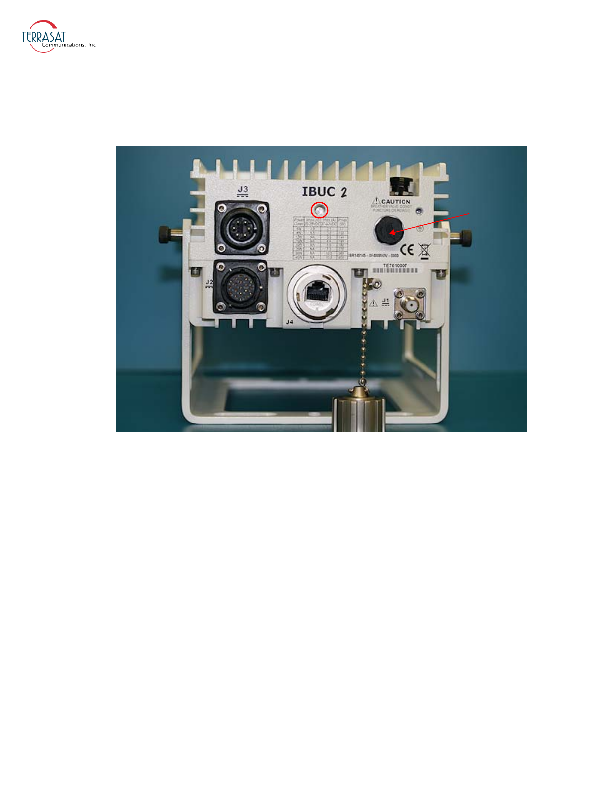
Figure 2.1 depicts the front panel of a DC-powered IBUC 2.
Mounting
Hole
Breather
Valve
Note:
The IBUC 2 pictured in Figure 2.1 has an F-type connector at J1.
Figure 2.1
Front Panel of a DC-powered IBUC 2
2-8 | IBUC 2, IBUC 2e, IBUC 2G, IBUC R Operations Manual: Functional Description
Page 31
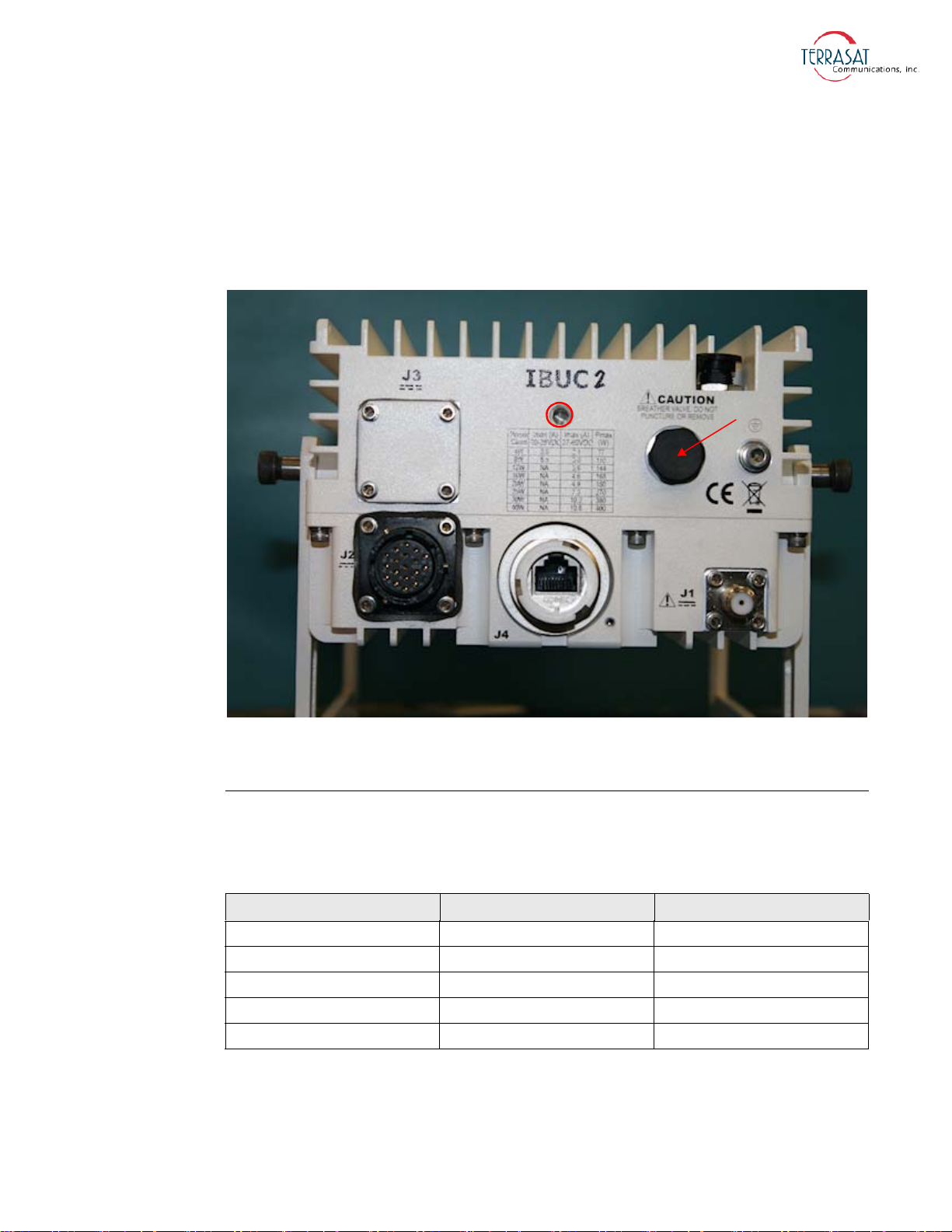
Figure 2.2 depicts the front panel of a low energy consumption IBUC 2e.
Mounting
Hole
Breather
Valve
Note:
The IBUC 2e pictured in Figure 2.2 has a plate covering the connector at J3. This is
because the low energy consumption IBUC 2e is powered only via coaxial cable
through connector J1.
Figure 2.2
Front Panel of a Low Energy Consumption IBUC 2e
AC Supply
Some IBUCs are available with optional AC power. Table 2.5 lists the voltage ranges
for different bands and power levels.
Table 2.5
Voltage Band Watts
100 VAC to 240 VAC C-band 5 watt to 50 watt
100 VAC to 240 VAC X-band 5 watt to 50 watt
100 VAC to 240 VAC Ku-band 4 watt to 40 watt
100 VAC to 240 VAC DBS-band 5 watt to 25 watt
100 VAC to 240 VAC Ka-band 5 watt to 10 watt
AC Supply Operating Voltage Ranges
System Components | 2-9
Page 32
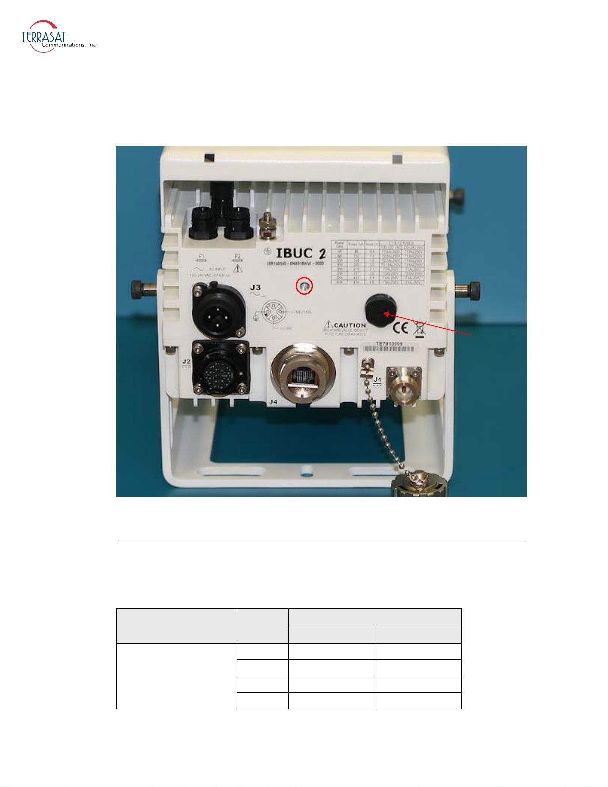
Figure 2.1 depicts the front panel of an AC-powered IBUC 2.
Mounting
Hole
Breather
Valve
Note:
The IBUC 2 pictured in Figure 2.1 has an N-type connector at J1.
Figure 2.3
Front Panel of an AC-powered IBUC 2
Fuses
Table 2.6 lists the the fuse markings of the fuses required by different AC-powered
IBUC models. Table 2.7 on page 2-12 defines the international marking schema.
Table 2.6
C-band
2-10 | IBUC 2, IBUC 2e, IBUC 2G, IBUC R Operations Manual: Functional Description
Fuse Markings
Signal
Fuse Markings
Power
Level
5 W T1.6AL250V T1.6AL250V
10 W T2AL250V T1.6AL250V
15 W T2.5AL250V T1.6AL250V
20 W T3.15AL250V T1.6AL250V
115 VAC 230 VAC
Page 33
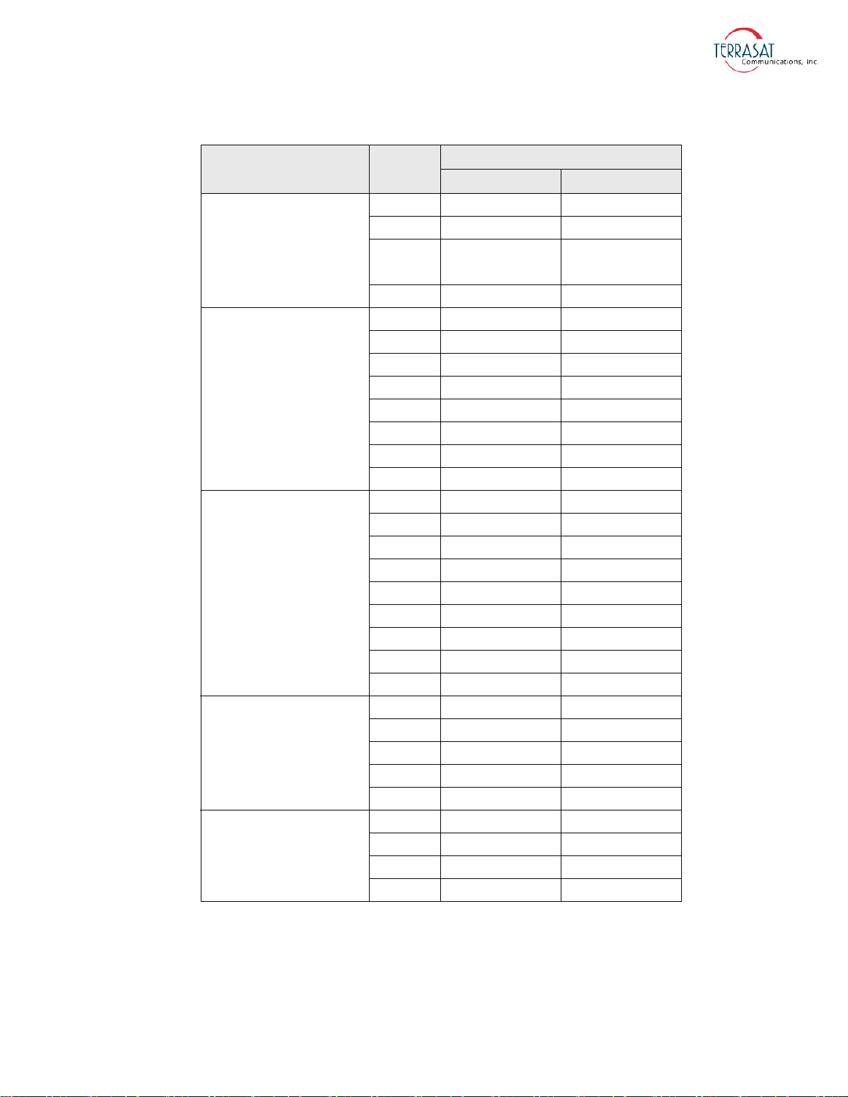
Table 2.6
Fuse Markings (Continued)
C-band
X-band
Ku-band
DBS-band
Ka-band
Signal
Power
Level
25 W T4AL250V T2AL250V
30 W T4AL250V T2AL250V
40 W T5AL250V T2.5AL250V
50 W T5AL250V T2.5AL250V
60 W T6.3AL250V T3.15AL250V
5 W T1.6AL250V T1.6AL250V
10 W T2AL250V T1.6AL250V
20 W T3.15AL250V T1.6AL250V
25 W T4AL250V T2AL250V
40 W T6.3AL250V T3.15AL250V
50 W T6.3AL250V T3.15AL250V
60 W T8AL250V T4AL250V
80 W T10AL250V T5AL250V
4 W T1.6AL250V T1.6AL250V
8 W T2.5AL250V T1.6AL250V
12 W T2.5AL250V T1.6AL250V
16 W T3.15AL250V T1.6AL250V
20 W T4AL250V T2AL250V
25 W T5AL250V T2.5AL250V
30 W T8AL250V T4AL250V
40 W T8AL250V T4AL250V
50 W T10AL250V T5AL250V
5 W T2AL250V T1.6AL250V
8 W T2.5AL250V T1.6AL250V
10 W T2.5AL250V T1.6AL250V
20 W T5AL250V T2.5AL250V
25 W T5AL250V T2.5AL250V
5 W T1.6AL250V T1.6AL250V
10 W T2AL250V T1.6AL250V
16 W T3.15AL250V T1.6AL250V
20 W T4AL250V T2AL250V
Fuse Markings
115 VAC 230 VAC
Note:
For IBUCs that require fuses up to 6.3 A, Terrasat recommends time lag fuses with a
high I2t value.
For IBUCs that require fuses greater than 6.3 A, Terrasat recommends time lag fuses.
System Components | 2-11
Page 34

For reference, IBUCs are delivered with Littelfuse 213 Series fuses (surge withstand,
time lag for up to 6.3 A) or 218 Series fuses (time lag for greater than 6.3 A).
Table 2.7 explains the fuse marking schema.
Table 2.7
T = Träge (Slow Blow)
Fuse Markings Explained
T 3,15A L 250V
250V = 250 Volts
L = Low Breaking Capacity (glass body)
3,15A = 3,15 Amp
Monitor and Control
Each IBUC is equipped with extensive monitor and control (M&C) capabilities. Use
any of the following methods to access those capabilities:
• Via the M&C 19-pin circular connector (J2) utilizing two-wire RS485. This
method requires that a separate cable must be run and connected to J2.
• Via the J2 connector using RS232. This method requires that a separate cable must
be run and connected to J2.
Figure G.1 on page G-2 contains a drawing for fabricating your own cable.
• Via the J4 connector using TCP/IP. This method requires a separate Ethernet
cable.
Note:
Figure G.2 on page G-3 contains a drawing for fabricating your own cable.
• Via the J2 connector using an optional hand-held terminal. The hand-held terminal
has its own cable.
• Via the L-band input N-connector or F-connector (J1) utilizing frequency shift
keying (FSK). Using this method requires no additional cable(s) but does require
that the FSK be multiplexed onto the L-band cable.
Some modem manufacturers offer built-in FSK capabilities for communicating with
the IBUC through the L-band IFL. Refer to the modem manufacturer’s documentation
for more information.
RF Signal Flow
L-band input to the IBUC is through the input N-connector or the F-connector (labeled
J1). Required inputs include an L-band signal at -20 dBm or less and a 10 MHz sine
wave reference signal between +5 dBm and -12 dBm (for those units that do not have
the optional internal 10
MHz reference signal).
2-12 | IBUC 2, IBUC 2e, IBUC 2G, IBUC R Operations Manual: Functional Description
Page 35
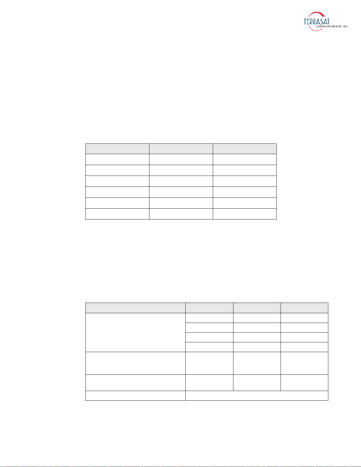
The US National Institute of Standards and Technology defines single sideband (SSB)
phase noise as the ratio of the spectral power density measured at an offset frequency
from the carrier to the total power of the carrier signal. The most generally used phase
noise unit of measure has been the single sideband power within a one hertz
bandwidth at a frequency f away from the carrier referenced to the carrier frequency
power. This unit of measure is represented as L (f) in units of dBc/Hz. An internal
phase-locked Local Oscillator provides excellent phase noise when locked to an
external 10 MHz reference. Single sideband phase noise using an external reference
signal is listed in Table 2.8.
Note:
Table 2.8
Condition External Reference IBUC
10 Hz
100 Hz
1 kHz
10 kHz
100 kHz
1 MHz
External 10 MHz Reference Signal Parameters
-115 dBc/Hz -54 dBc/Hz
-140 dBc/Hz -79 dBc/Hz
-150 dBc/Hz -89 dBc/Hz
-155 dBc/Hz -94 dBc/Hz
n/a -100 dBc/Hz
n/a -110 dBc/Hz
The internal 10 MHz reference signal meets the minimum phase noise requirements
listed in Table 2.9.
If an external 10 MHz reference signal is applied to a unit with the optional internal
10 MHz reference signal, the external signal has priority. When the external signal is
removed from such units, the system automatically reverts to the internal 10 MHz
signal, requiring no additional user input.
Table 2.9
Phase Noise
Frequency Stability vs. Operating
Temperature Range
(referenced to frequency at +25 °C)
Tuning Range
(referenced to nominal frequency)
Tuning Slope Positive
Internal 10 MHz Reference Signal Parameters
Minimum Maximu m Condition
-100 ppb +100 ppb -40 °C to +85 °C
±3 ppm ±10 ppm
-100 dBc/Hz 10 Hz
-130 dBc/Hz 100 Hz
-140 dBc/Hz 1 kHz
-145 dBc/Hz 10 kHz
Input to the IBUC also includes AC or DC voltage (via the J3 connector) and DC
voltage for low-power units and an FSK signal via the J1 connector. The input
System Components | 2-13
Page 36

(L-band, FSK, 10 MHz, and DC via coaxial cable) is routed to the demultiplexer
circuitry where the various signals are split off and routed to the appropriate circuits
within the IBUC. (Only IBUCs with direct DC or AC via the J3 connector feed the
power supply directly.) The input voltage from the demultiplexer circuitry is routed to
the power supply and the FSK signal is routed to the M&C card.
The external 10 MHz reference signal is routed to the multiplier circuitry where its
level is first detected and an alarm issued if the signal is low. However, if the signal
level is low and the system is equipped with the optional internal 10 MHz signal, the
system will automatically switch to the internal 10 MHz signal. The 10 MHz signal is
then multiplied to the frequency used for phase-locking purposes. The output of the
multiplier is routed to the phase detector circuitry where it is compared with the phase
of the DRO (dielectric resonator oscillator) signal sample and consequently generates
a voltage that is applied as a control voltage to the DRO to adjust its frequency. The
DRO has been optimized for phase noise at a single frequency based on the frequency
band of that particular IBUC. The output of the DRO is amplified and routed to the
mixer.
The L-band signal that is split off in the demultiplexer circuitry is first filtered and a
sample of it detected for input power detection and control purposes. The signal is
then amplified, and goes through a variable attenuator. The attenuation is used to
provide an attenuation adjustment of 30 dB in 0.1 dB steps and to provide automatic
level control (ALC) or automatic gain control (AGC).
Note:
Note:
After additional amplification and filtering, the signal is routed to the mixer. The
L-band signal is then mixed with the DRO signal to “upconvert” to the appropriate RF
signal based on the frequency band of the IBUC. The RF signal is filtered, amplified,
and then routed to the temperature compensation circuitry. The temperature
compensation circuitry has been calibrated so that the IBUC gain does not vary more
than 3 dB at any given frequency.
Some units can vary up to 4 dB at any given frequency.
The signal is then routed through an isolator to the solid-state power amplifier (SSPA).
Some models have an additional mechanical filter between the isolator and the SSPA.
The SSPA amplifies the signal which is then routed to the output through an isolator
for reverse power protection. The RF output is detected for M&C purposes. The IBUC
gain has been calibrated so that at minimum attenuation, a -30 dBm input results in
rated power of at least P1dB at the output at any frequency or temperature.
Ka-band BUC rated power is measured at P
SAT
.
To operate at lower power levels, reduce the input to the IBUC or reduce the IBUC
gain by using the variable attenuator, accessible using any of the M&C interfaces. The
output of a C-band IBUC 2 is a CPR137G waveguide or an N-type connector, the
2-14 | IBUC 2, IBUC 2e, IBUC 2G, IBUC R Operations Manual: Functional Description
Page 37

output of an X-band is a CPR112G waveguide, the output of a Ku-band IBUC 2 is a
WR75 cover with groove waveguide, the output of a DBS-band IBUC 2 is a
WR62 UG cover with groove waveguide, and the output of a Ka-band IBUC 2 is a
WR28
UG cover with groove waveguide.
Figure 2.4 depicts the signal flow for units that are DC powered, Figure 2.5 depicts the
signal flow for units that are AC powered, and Figure 2.6 depicts the signal flow for
DC-powered low energy-consumption units.
System Components | 2-15
Page 38
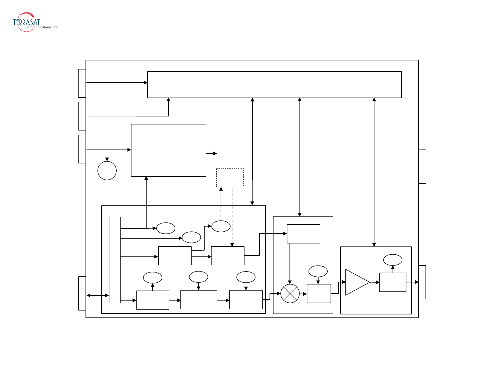
J1
J2
RF OUT
FAN
Monitor and Control (M&C)
RS485
RS232
HHT
Alarm
Switch Control
VDC
VDC
FSK
External 10 MHz
L-band
DC/DC
Power Supply
De-Mux
Detector
Multiplier
Detector
Gain Adjust ALC/AGC
External
10 MHz
M&C
M&C
M&C
M&C
M&C
M&C
FSK
PL DRO
M&C
Temp
Comp
SSPA
M&C
Detector
Internal
10 MHz
All Circuits
VDC
M&C
J3
J4
TCP/IP
Figure 2.4
2-16 | IBUC 2, IBUC 2e, IBUC 2G, IBUC R Operations Manual: Functional Description
DC-powered IBUC Block Diagram
Page 39
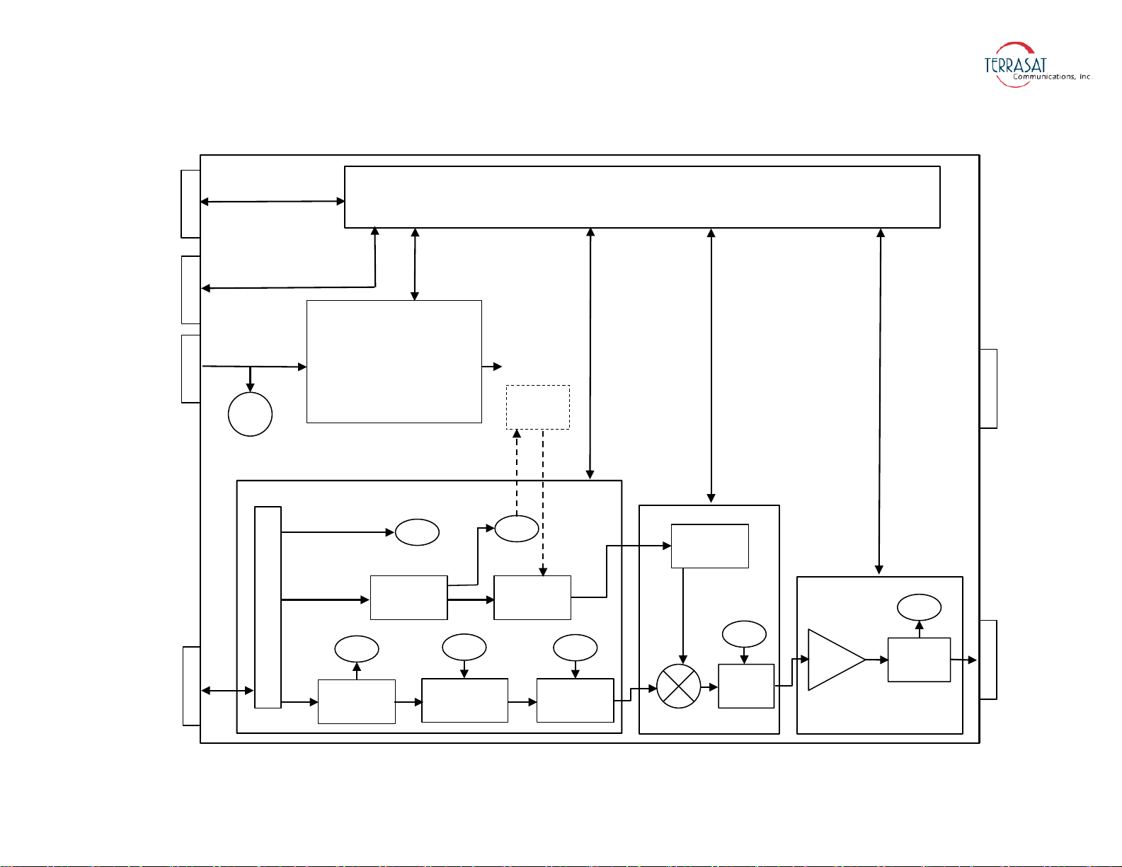
J1
J2
RF OUT
FAN
Monitor and Control (M&C)
RS485
RS232
HHT
Alarm
Switch Control
VAC
FSK
External 10 MHz
L-band
AC/DC
Power Supply
De-Mux
Detector
Multiplier
Detector
Gain Adjust ALC/AGC
External
10 MHz
M&C
M&C
M&C
M&C
M&C
FSK
PL DRO
M&C
Temp
Comp
SSPA
M&C
Detector
Internal
10 MHz
All Circuits
M&C
J3 J4
TCP/IP
Figure 2.5
AC-powered IBUC Block Diagram
System Components | 2-17
Page 40
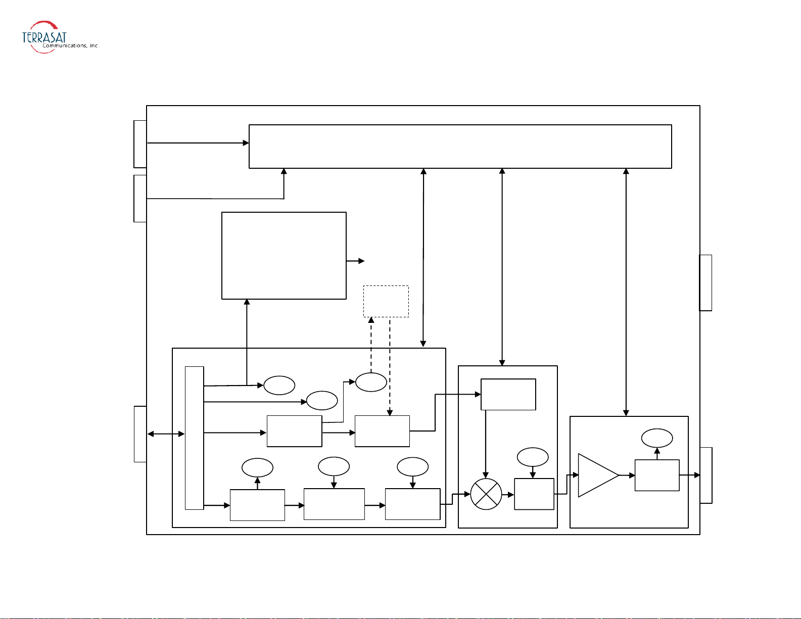
J1
J2
RF OUT
FAN
Monitor and Control (M&C)
RS485
RS232
HHT
Alarm
Switch Control
VDC
FSK
External 10 MHz
L-band
DC/DC
Power Supply
De-Mux
Detector
Multiplier
Detector
Gain Adjust ALC/AGC
External
10 MHz
M&C
M&C
M&C
M&C
M&C
M&C
FSK
PL DRO
M&C
Temp
Comp
SSPA
M&C
Detector
Internal
10 MHz
All Circuits
VDC
J4
TCP/IP
Figure 2.6
2-18 | IBUC 2, IBUC 2e, IBUC 2G, IBUC R Operations Manual: Functional Description
IBUC 2e Block Diagram (for DC-powered low energy-consumption systems)
Page 41

Software
The IBUC 2, IBUC 2e, IBUC 2G, or IBUC R monitors and controls numerous
parameters and has features which simplify installation and use and enhance system
performance.
Some of these key features include:
• Monitor and Control
The IBUC can be monitored and controlled through an assortment of interfaces
including RS232, RS485, Ethernet port, an optional hand-held terminal, or via an
FSK link with compatible modems. The FSK link is multiplexed on the L-band
IFL thus eliminating the need for an additional cable and simplifying installation.
Chapter 5, Monitor and Control Features, for a full description of these
See
functions.
• Tx Attenuation
The gain of the unit can be set over a 30 dB range in 0.1 dB steps.
• Automatic Gain Control (AGC)
The IBUC continuously monitors input and output levels. When AGC is enabled,
the gain of the system is maintained at a constant level by an internal algorithm.
Gain is the difference between output power and input power.
• Automatic Level Control (ALC)
Similar to the AGC system, when ALC is enabled, the gain is adjusted to maintain
a constant output level.
• Redundancy
The IBUC automatically senses when configured as a redundant system. This logic
is built-in—eliminating the need for an external switching controller.
• Embedded Web Pages
Provides management for small networks by using a Web browser.
• Simple Network Management Protocol (SNMP)
Provides integration of IP M&C in existing network management systems.
• Burst Operation
Enables operation in burst mode. The IBUC 2 reports average output power of
valid bursts (above a burst threshold) when in burst mode.
• Alarm History (with time stamps)
A log of alarms that occur is maintained. This can simplify troubleshooting of the
system (especially when an intermittent problem occurs).
System Components | 2-19
Page 42

•Sensors
A series of internal sensors enable you to verify performance and to troubleshoot
the system. Sensors include internal temperature, 10 MHz input detector, supply
voltage, current consumption, phase-locked dielectric resonator oscillator
(PLDRO) lock voltage, input level and output level.
System Configurations
Figure 2.7 to Figure 2.9 show typical earth station installations using Terrasat block
upconverters. In normal operation, the IBUC 2 and the low-noise block
downconverter (LNB) are mounted outdoors. Depending on the model of the IBUC 2,
the PSUI can be mounted indoors or outdoors. The IBUC 2 and the LNB can interface
directly with a satellite modem, a 70
combiner network, or an interface unit (IFU).
proper operation.
MHz to L-band rack converter, a modem
Table 2.10 lists the requirements for
Table 2.10
IBUC 2 LNB
DC supply DC supply
~ from the modem ~ from the modem
~ from the IFU ~ from the IFU
~ from the outdoor PSUI 10 MHz reference signal
~ from the indoor PSUI ~ internally referenced
~ from the telecom station ~ externally referenced
AC supply ~ free running
~ AC mains RF input
10 MHz reference signal ~ from the antenna
~ internally referenced
~ externally referenced
Basic System Requirements
L-band signal
Certain considerations must be made when selecting the IFL because appropriate
shielding and signal levels are required for normal system operation. The IBUC 2 is
designed to operate with a -30
dBm Tx L-band input signal to achieve rated power at
maximum gain/minimum attenuation. The IBUC 2, IBUC 2e, IBUC 2G, or IBUC R
provides a variable attenuator that is accessible through the various M&C interfaces
that enables the gain of the unit to be reduced by up to 30 dB in 0.1 dB steps. The
2-20 | IBUC 2, IBUC 2e, IBUC 2G, IBUC R Operations Manual: Functional Description
Page 43

attenuator can be used to prevent overdrive to the IBUC in configurations with a short
cable run (or IFL), thus preserving the dynamic range of the modem. In addition, the
internally referenced IBUC and the internally referenced LNB must have a 10 MHz
input signal at +5
The maximum voltage drop for a 24
dBm to -12 dBm for the IBUC, and 0 dB to -10 dBm for the LNB.
VDC IBUC is 4 volts and the maximum drop for
a 48 VDC IBUC 2 is 11 volts. For AC-powered IBUCs, the range is 100 VAC to
240 VAC.
Note:
The system configurations in Figure 2.7 to Figure 2.9 depict an external 10 MHz
reference signal; however, an optional internal 10 MHz reference signal is available.
System Components | 2-21
Page 44
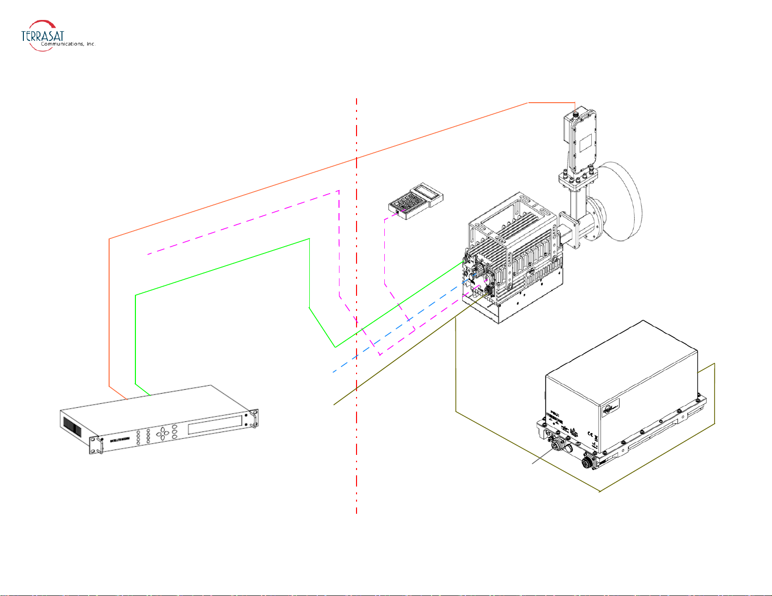
←
R
S
2
3
2
o
r
R
S
4
8
5
→
←
F
S
K
→
T
x
L
-
b
a
n
d
/
1
0
M
H
z
/
D
C
P
o
w
e
r
→
←
R
x
L
-
b
a
n
d
1
0
M
H
z
a
n
d
V
D
C
→
S
A
T
E
L
L
I
T
E
M
O
D
E
M
P
O
W
E
R
S
U
P
P
L
Y
U
N
I
T
(
o
p
t
i
o
n
a
l
)
I
B
U
C
2
LNB
Hand-Held
Terminal
OUTDOOR EQUIPMENTINDOOR EQUIPMENT
48 VDC
100-240 VAC
T
x
L
-
b
a
n
d
R
x
L
-
b
a
n
d
D
C
P
o
w
e
r
→
↑
D
C
P
o
w
e
r
←
E
t
h
e
r
n
e
t
→
Figure 2.7
2-22 | IBUC 2, IBUC 2e, IBUC 2G, IBUC R Operations Manual: Functional Description
DC Power System Configuration
Page 45

Rx L-band
Tx L-band / FSK
I
F
U
S
A
T
E
L
L
I
T
E
M
O
D
E
M
4
8
V
D
C
P
O
W
E
R
S
U
P
P
L
Y
U
N
I
T
(
o
p
t
i
o
n
a
l
)
I
B
U
C
2
LNB
Hand-Held
Terminal
OUTDOOR EQUIPMENTINDOOR EQUIPMENT
←
R
S
2
3
2
o
r
R
S
4
8
5
→
←
F
S
K
→
T
x
L
-
b
a
n
d
/
1
0
M
H
z
/
D
C
P
o
w
e
r
→
←
R
x
L
-
b
a
n
d
1
0
M
H
z
a
n
d
V
D
C
→
←
E
t
h
e
r
n
e
t
→
↑
D
C
P
o
w
e
r
1
0
0
-
2
4
0
V
A
C
Figure 2.8
DC Power System Configuration with IFU
System Components | 2-23
Page 46
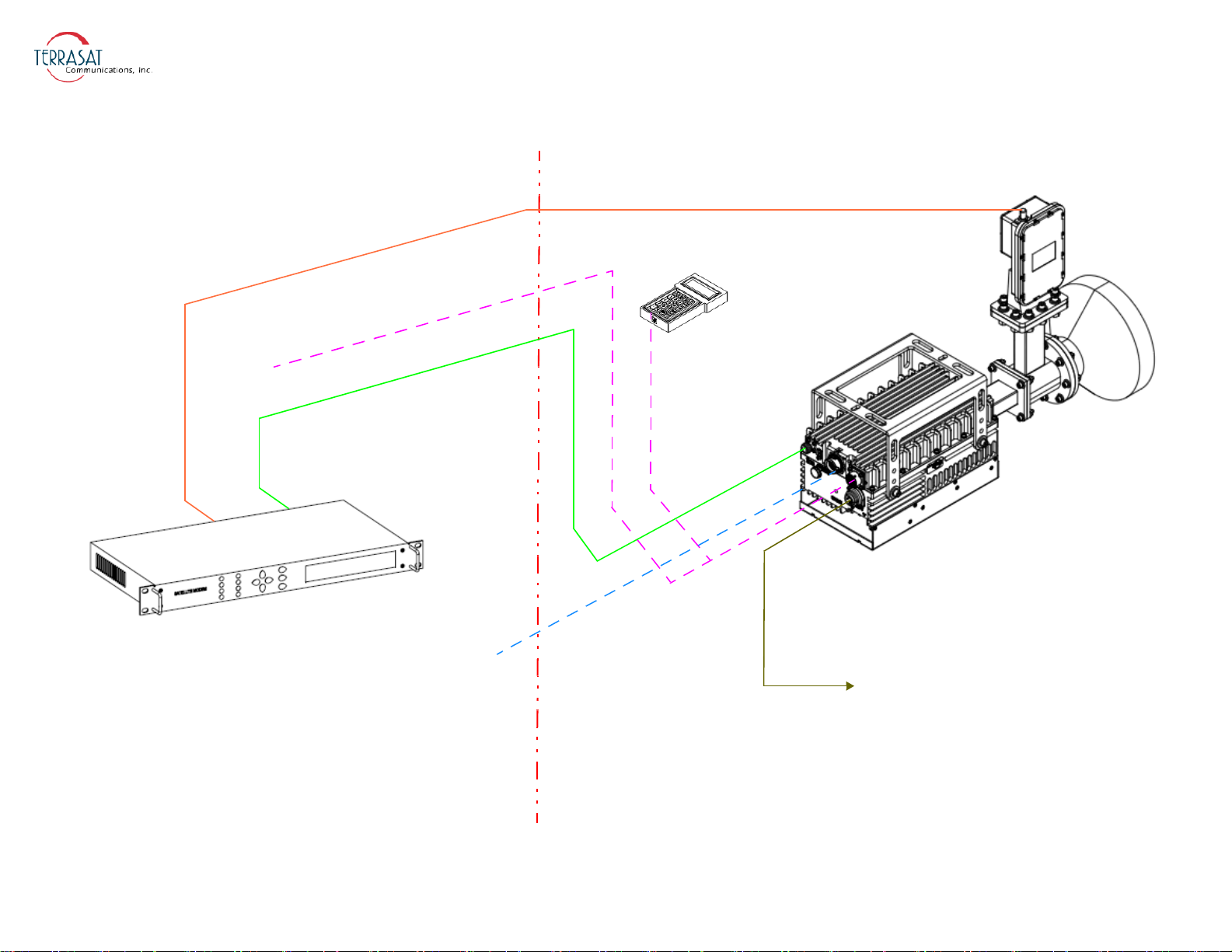
I
B
U
C
2
LNB
Hand-Held
Terminal
S
A
T
E
L
L
I
T
E
M
O
D
E
M
OUTDOOR EQUIPMENTINDOOR EQUIPMENT
←
R
S
2
3
2
o
r
R
S
4
8
5
→
←
F
S
K
→
T
x
L
-
b
a
n
d
/
1
0
M
H
z
→
←
R
x
L
-
b
a
n
d
1
0
M
H
z
a
n
d
V
D
C
→
100-240 VAC
←
E
t
h
e
r
n
e
t
→
Figure 2.9
AC Power System Configuration
2-24 | IBUC 2, IBUC 2e, IBUC 2G, IBUC R Operations Manual: Functional Description
Page 47

Storage Information
There are no storage limitations on the IBUC 2, IBUC 2e, IBUC 2G, or IBUC R, or
redundant (1+1) interfaces for redundant systems other than avoiding excessive
exposure beyond the -45
°C to +65 °C external ambient temperature.
System Components | 2-25
Page 48

2-26 | IBUC 2, IBUC 2e, IBUC 2G, IBUC R Operations Manual: Functional Description
Page 49
This chapter contains the general requirements for installing the Terrasat outdoor unit
(ODU).
Introduction
The ODU consists of an intelligent block upconverter (IBUC) and a low-noise block
converter (LNB). An indoor interface unit (IFU) and a power supply (PSUI) can also
be part of the configuration.
C HAPTER
C
HAPTER
3
I
NST ALLATION
General Requirements
Unpacking
Check to make sure that the ODU has not been damaged in shipment. If there is any
damage, contact the shipper before proceeding. If you need to declare any equipment
WARNING
For protection of personnel and equipment, use care
when installing the antenna and whenever working
on or around the system.
Follow standard safety precautions with hand or
power tools.
Use care when working with high AC voltages and
microwave emissions.
Page 50

as damaged during transit, save the original shipping cartons to ease inspection
reporting.
Terrasat recommends retaining and re-using all shipping cartons and foam forms if the
equipment will be stored or reshipped. The cartons should be clearly marked to
indicate that they contain fragile electronic equipment.
Compare the contents of the shipping container with the packing list to ensure that all
items have been received. If any item is missing, contact Terrasat.
Furnished Items
The following items are furnished with Terrasat Communications, Inc. IBUCs:
•An IBUC 2, IBUC 2e, IBUC 2G, or IBUC R with an integrated solid state power
amplifier (SSPA)
• Product documentation on CD
• Waveguide gaskets and hardware (waveguide units only)
• Test datasheet
• DC supply mating connector (for units with DC supply)
Figure G.4 on page G-5 contains information about fabricating your own DC
supply cable.
• AC supply mating connector (for units with AC supply
Figure G.5 on page G-6 contains information about fabricating your own DC
supply cable
• Sealing tape for Type-N connector
•5 g pouch of Permatex anti-seize lubricant
The anti-sieze lubricant is a heavy duty high-temperature lubricant that prevents
galling (friction between metal parts that can weld the nut and bolt together and
prevent removal), seizing, and corrosion of fasteners during assembly and aids the
disassembly of parts exposed to heat or corrosive environments.
•Fuses
The fuses are intended for 220 VAC operation and are only supplied with units
that operate over the range of 100
VAC to 240 VAC.
• 19-pin monitor and control (M&C) mating connector (optional)
• IP67 industrial RJ45 mating connector (optional)
• Mounting brackets and bolts (optional)
3-2 | IBUC 2, IBUC 2e, IBUC 2G, IBUC R Operations Manual: Installation
Page 51
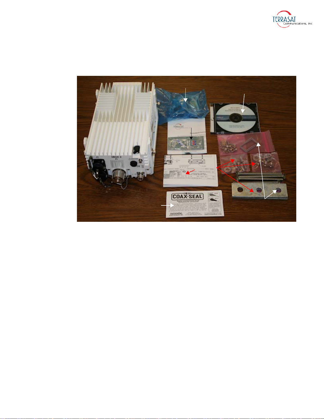
Figure 3.1 illustrates the contents of the shipping carton of an IBUC 2 as it leaves the
IBUC 2
Mating Power
Connector
Product
Documentation on CD
Assorted
Hardware
Sealing
Tape
Installation Drawing
Permatex
Lubricant
optional
items
factory.
Note:
Figure 3.1
Contents of an IBUC 2 Shipping Carton
Accessories
The following are optional accessories:
• A hand-held terminal and cable
• A waveguide Rx reject filter
• A four-way combiner/divider module
• A TCP/IP test cable
• Waveguide pieces
• IFL cables (for example, LMR-400)
• Installation kits
Exact contents of the shipping carton vary according to the model and type of IBUC.
General Requirements | 3-3
Page 52

Installing the ODU
Consider the following when preparing to install the ODU.
Tools
Have available a standard electrician’s toolkit and any tools listed in the antenna
manufacturer’s installation instructions.
Test Equipment
Terrasat recommends the equipment or its equivalent listed in Table 3.1 for
installation and system alignment.
Table 3.1
Equipment Type
Spectrum Analyzer Agilent HP8563E
Digital Voltmeter Fluke 8050
Waveguide-to-coaxial Adapter C-band or Ku-band
RF cables With calibrated insertion loss up to 15 GHz
40 dB attenuator High power to match HPA output
Assortment of cables, connectors and adapters
(calibrated up to 15 GHz)
Recommended Test Equipment
Site Considerations
The ODU is designed to be mounted on or near the antenna. Locate and install the
antenna according to instructions supplied by the antenna manufacturer. Choose an
area that is free of interference from motors or other electrical equipment and that has
a clear line of sight from the antenna to the satellite. Use size 3/0 or 4/0 AWG
(American Wire Gauge) stranded copper wire to ground the IBUC 2, IBUC 2e,
2G, or IBUC R to the antenna frame and to the lightning protection ground
IBUC
rod. For higher power units with an external power supply, Terrasat recommends
using an isolation filter to reduce power line interference.
Mounting Considerations
Optional mounting brackets are available to aid mounting on most antennas.
The ODU must be mounted such that:
• The IBUC has sufficient support to minimize the effects of antenna sway in strong
winds.
• The fan intake and exhausts are free from any obstructions.
• The heat fins have air movement across them.
3-4 | IBUC 2, IBUC 2e, IBUC 2G, IBUC R Operations Manual: Installation
Page 53
Throughout installation and during any polarization, azimuth or elevation adjustment,
ensure that cables and waveguide are not crimped or pinched. Ensure that there is
adequate slack in the cable.
Power Requirements
WARNING
Installation and connection to the line power supply
must be made in compliance with applicable wiring
codes and regulations.
For DC-powered IBUC models with a rated power level of 25 watts or below for
C-band, 20 watts and below for X-band, 16 watts and below for Ku-band, 8 watts and
below for DBS-band, and 10 watts and below for Ka-band, the power for the IBUC
can come either from the IFL supplied from the Terrasat indoor unit (IDU) equipped
with a 200 watt power supply or from a satellite modem equipped with a suitable
power supply. DC power for these lower power IBUCs can also be supplied directly
through the external power connector (J3) by using the Terrasat 250- watt external
power supply. Refer to the part number label (shown in Figure A.1 on page A-1) to
determine voltage requirements. Ensure that 24 VDC input voltage is from 20 VDC to
28 VDC and that the 48 VDC input is from 37 VDC to 60 VDC.
Note:
Note:
Power for the IBUC 2e comes only via coaxial cable. Refer to the datasheet in
Appendix G, Component Specifications and Reference Drawings for power
requirements.
Outdoor Power Supply
Terrasat offers four models of outdoor power supplies. DC-powered IBUCs with a
rated power level higher than 25 watt C-band, 25 watt X-band, 16 watt Ku-band, or
10 watt DBS-band require a separate power supply. Units that get their power from the
earth (or telecom) station do not require an external power supply. Table 3.2 lists the
four outdoor power supply models and applications for each. Power supplies have an
autoranging AC front end that works with both 115
VAC and 230 VAC.
The IBUC is configured at the factory to be floating. Ensure that the correct polarity is
applied to any unit.
General Requirements | 3-5
Page 54
Table 3.2
Model Output Power Application
PSUI-948-0250S-4 250 W
PSUI-948-600-4 600 W
PSUI-948-1000-4 1000 W
Terrasat Outdoor Power Supplies
• C-band up to 25 W
• X-band up to 25 W
• Ku-band up to 16 W
• Ka-band up to 16 W
• DBS-band up to 10 W
• C-band up to 80 W
• X-band up to 80 W
• Ku-band up to 50 W
• Ka-band up to 40 W
• DBS-band up to 25 W
• C-band 100 W to 125 W
• X-band 100 W to 125 W
• Ku-band 60 W to 80 W
PSUI-948-600-4 1200 W
• C-band 150 W to 200 W
• X-band 150 W to 175 W
All IBUCs that are AC-powered and all Terrasat outdoor PSUIs are furnished with a
detachable AC power connector that is used to connect and disconnect power. When
connecting the AC connector the the AC power source, the wiring must include a
15 amp or 20 amp circuit breaker. A disconnect device (such as a circuit breaker or
mains supply plug on the power supply cord) that is readily accessible must also be
provided. Any outdoor AC connections should be made using suitable connectors or
boxes with an IEC protection class of at least IP65.
WARNING
Ensure AC power is off when connecting or
disconnecting the power supply unit’s power cord.
To turn off AC power to the unit, use the installed
circuit breaker or a similar disconnecting device.
If a circuit breaker is not easily accessible as a disconnecting device, the input
connector will be the disconnecting device. In this case, the socket-outlet must be
installed near the equipment and must be easily accessible for pluggable equipment.
3-6 | IBUC 2, IBUC 2e, IBUC 2G, IBUC R Operations Manual: Installation
Page 55

All AC-powered IBUCs and the Terrasat outdoor PSUI are furnished with mating
connectors for the AC mains power cable. To remain compliant with European Low
Voltage Directive (EN 60950-1), use a power cable that meets IEC 60227
requirements such as HAR Cable Designation H03VV-F or H03VVH2-F and/or
others with water resistance for outdoor applications. Power cable plugs must also
comply with all applicable local and federal standards and regulations.
Indoor Power Supply
Terrasat offers a 1000 watt indoor power supply unit (PSUI) which provides 48 VDC
power. The 1000 watt PSUI can power C-band and X-band units through 125 watts,
Ku-band units through 80 watts, and Ka-band units through 40 watts. Each indoor
PSUI is packaged in a rack-mountable chassis which occupies one rack unit (1.75 in.)
of space. The indoor PSUI is shipped with a mating connector for DC power and a
power cord for AC mains.
Note:
AC transients and surges can cause data transmission errors and loss of
synchronization in the modem and/or the ODU. Take proper precautions to ensure
uninterrupted service.
Grounding
Terrasat recommends the following grounding and lightning protection:
• Cable Shielding
Shield currents can be eliminated with proper techniques. A grounding strap at the
end of the coaxial and data cables should be connected to the ground lug at the
antenna base with #4 gauge copper wire. This provides a path of least resistance
prior to entering the equipment.
•AC
The best way to protect the equipment is to have two protectors. The first is the
power mains protector that is mounted directly across the mains in the breaker box.
The second should be mounted or grounded directly at the base or hub of the
antenna or at the 19-in. rack.
• Data and Control Lines
The I/O lines can deliver surge current to the equipment and should also be
protected.
• Electrical Grounding
Grounding of the IBUC 2, IBUC 2e, IBUC 2G, or IBUC R and PSUI units is
recommended to prevent possible damage from lightning or other induced
electrical surges. Terrasat recommends using 3/0 or 4/0 AWG stranded copper
wire for bonding the IBUC and the PSUI to the earth ground (or grounding rod),
using the most direct or shortest route.
General Requirements | 3-7
Page 56

Antenna Recommendations
Most antenna masts are encased in concrete. Typically, the mast pipe is submerged in
a 4 ft to 5 ft (1.22 m to 1.53 m) deep augered hole. This provides a good Ufer ground.
A Ufer ground encases grounding connectors in concrete. Concrete absorbs moisture
quickly and loses that moisture slowly—as much 15 to 30 days after rain or snow
melt). The mineral properties of concrete and their natural pH mean that concrete has a
supply of ions to conduct current. The soil around concrete becomes “doped” by the
concrete and, as a result, the pH of the soil rises. The moisture in the concrete in
combination with the “doped” soil make a good connector of electrical energy. The
concrete’s large volume and area of contact with the surrounding soil allow a good
transfer to the ground. In the concrete base, a Ufer ground can be established by
running #4 gauge solid wire or rebar and connecting to the base of the pedestal with
pigtails.
The Ufer ground is only one step in proper grounding. The Ufer ground should be
augmented with coupled pairs of 10 ft (3.05 m) ground rods placed 20 ft (6.1 m) into
the ground, spaced 20 ft (6.1 m) apart. The first rod should be placed close to the
antenna. The second rod should be placed towards the equipment enclosure. A #2
gauge wire should connect the rods and antenna mount. A ground rod should be
placed at the equipment enclosure, as well. If it is virtually impossible to install the
ground rods, then radials are needed. This can be accomplished by laying 10 or more
lengths of 1½-in. (3.81 cm) copper strap at least 50 ft (15.24 m) long in a radial fashion
around the antenna base. The straps should be buried, if possible. The hub must be
interconnected to the utility ground.
Note:
The ground configuration can vary from one location to another. It is best to measure
soil conductivity and design a 5 Ω or less ground system. To protect the system from a
direct strike, a lightning rod placed 2 ft (61 cm) higher than the highest point of the
dish should be interconnected to the Ufer ground with #2 gauge copper wire.
Antenna Mounting
The IBUC has a variety of mounting options: on the focal point, the boom arm, the
antenna back structure, or in the hub (depending on the antenna type).
Figure 3.2 and Figure 3.3 are photographs of actual installations.
3-8 | IBUC 2, IBUC 2e, IBUC 2G, IBUC R Operations Manual: Installation
Page 57
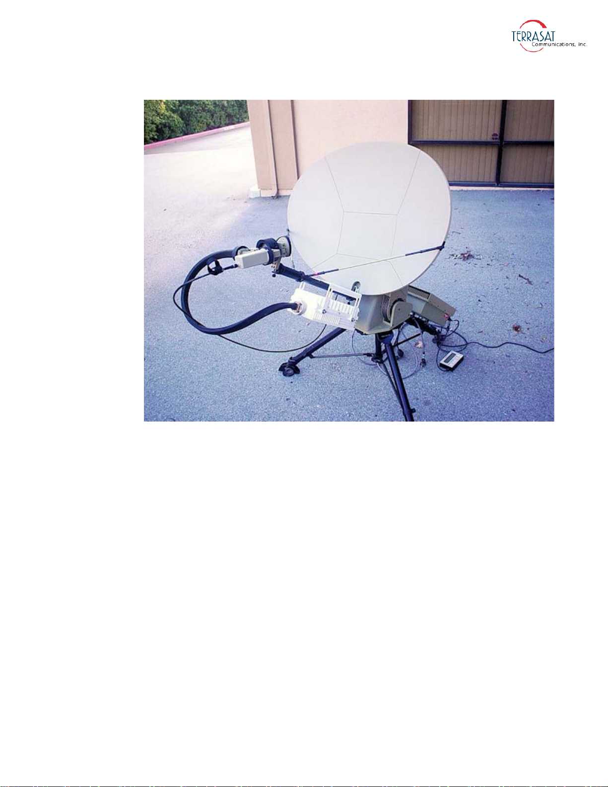
Figure 3.2
IBUC 2 Field Installation
General Requirements | 3-9
Page 58
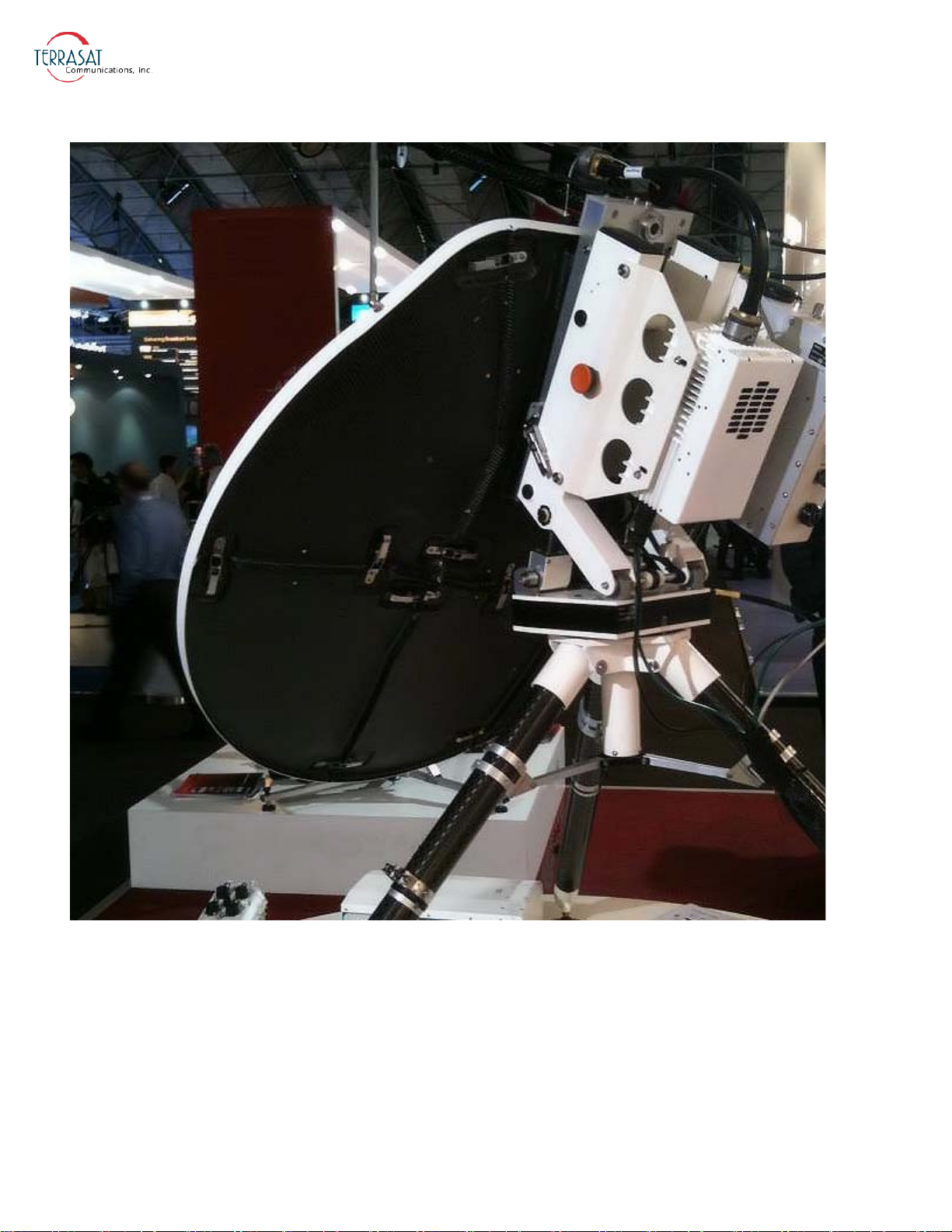
Figure 3.3
3-10 | IBUC 2, IBUC 2e, IBUC 2G, IBUC R Operations Manual: Installation
IBUC 2 Installation
Page 59
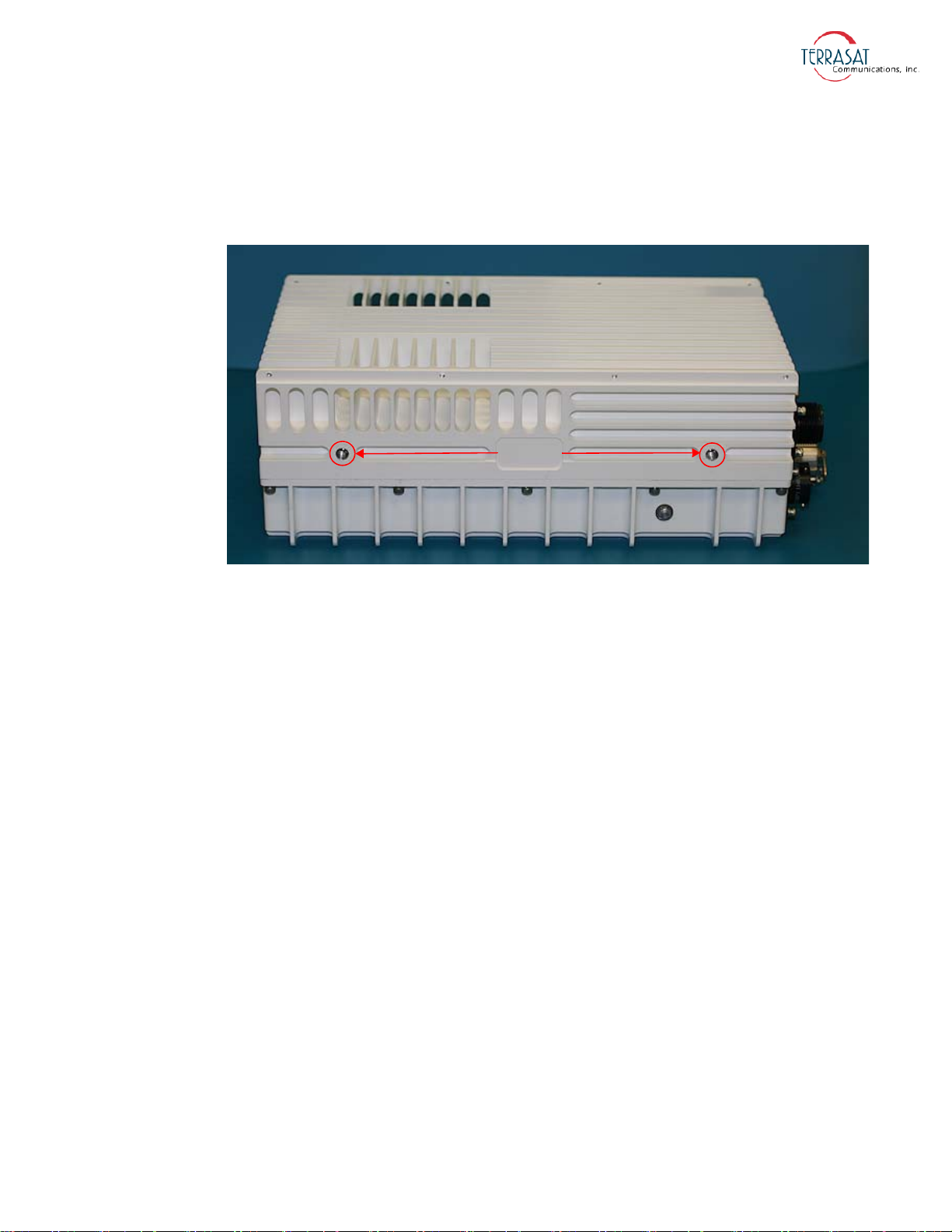
The IBUC 2, IBUC 2e, IBUC 2G, or IBUC R have mounting holes on both sides of
Mounting
Holes
the unit that can be used to attach the IBUC to the antenna. For the location of these
mounting holes, see Figure 3.4.
Figure 3.4
Location of Mounting Holes
There is also a single mounting hole located on the front of the IBUC that is identified
in Figure 2.1 and Figure 2.3 on page 2-10. This mounting hole is on the same axis as
the center of the waveguide of the unit (that is, it is in line with the center of the
waveguide). This single mounting hole enables the unit to be rotated when mounted on
the focal point of an antenna.
General Requirements | 3-11
Page 60
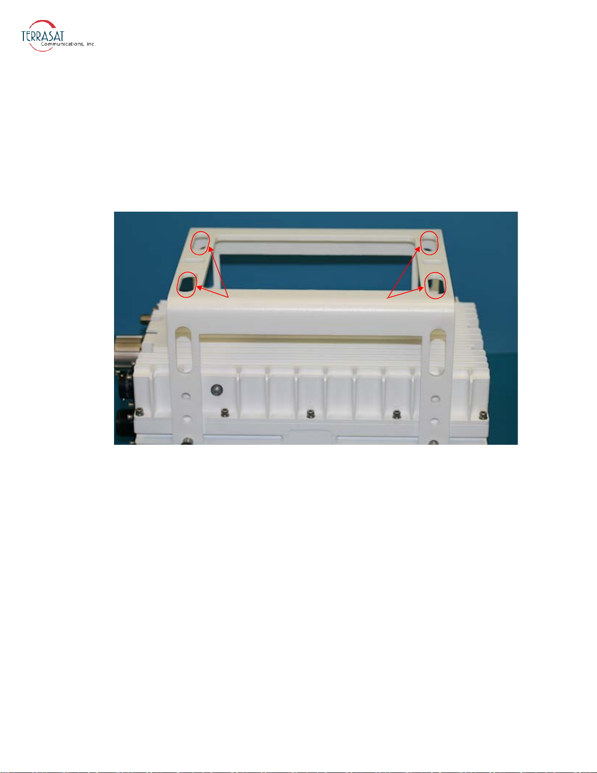
Optional mounting brackets are available that aid in attachment to antennas. The
Mounting Bracket Adjustment Slots
mounting slots identified in Figure 3.5 on page 3-12 give you additional flexibility
when attaching the IBUC to the antenna.
Note:
Ensure that the threads of the bolts used for mounting the IBUC have been dipped in
the included Permatex anti-sieze lubricant. This prevents galling, seizing, and
corrosion of fasteners during assembly and will aid in future disassembly. For more
information about applying the Permatex lubricant, see page 3-17.
Figure 3.5
Location of Adjustment Slots on Optional Mounting Bracket
System Pressurization
The IBUC chassis contains a breather valve (the location is identified in Figure 2.1
and Figure 2.3 on page 2-10) that is designed to equalize pressure inside and outside of
the unit while allowing the passage of air or water vapor but not environmental
contaminants such as liquids, debris, or dust. If you intend to pressurize the
waveguide, you must install a pressure window at the output of the IBUC; otherwise
the breather valve will not permit pressurization of the system.
3-12 | IBUC 2, IBUC 2e, IBUC 2G, IBUC R Operations Manual: Installation
Page 61

System Cabling Requirements
Cables and Connectors
Interface connectors for the IBUC 2, IBUC 2e, IBUC 2G, or IBUC R and their mates
are listed in Table 3.3. Additional mating connectors and/or cables can be ordered
from Terrasat at optional items.
Table 3.3
REFERENCE
DESIGNATOR
J1 Tx Input
J2 M&C Interface
J3 DC Power
1
J3
J4 Ethernet
RF OUTPUT C-band
RF OUTPUT X-band CPR112, CPRG WAVEGUIDE CPR112, CPRF WAVEGUIDE
RF OUTPUT Ku-band
RF OUTPUT DBS-band
RF OUTPUT Ka-band
Interface Connector Schedule
FUNCTION
TYPE-N SOCKET
(TYPE-F SOCKET optional)
AMPHENOL CIRCULAR, BOX
MOUNTING SOCKET, 19S
(PT02E-14-19S (027))
AMPHENOL CIRCULAR, BOX
MOUNTING SOCKET
(ACS02E14S-6P (553))
CONNECTOR, MALE
AC Power
RECEPTACLE, 3+PE
(AMPHENOL C016 20C003 100 12)
RJ45-IP67 SHIELDED INLINE
CONNECTOR WITH CAP
CPR137, CPRG WAVEGUIDE OR
TYPE-N SOCKET
WR75 COVER FLANGE WITH
GROOVE
WR62 COVER FLANGE WITH
GROOVE
WR28 COVER FLANGE WITH
GROOVE
INTERFACE
CONNECTOR
INTERFACE
CONNECTOR MATE
TYPE-N PLUG
(TYPE-F PLUG optional)
AMPHENOL CIRCULAR, STRAIGHT
PLUG, 19P
(PT06E-14-19P (475))
AMPHENOL CIRCULAR STRAIGHT
PLUG
(ACS06E14S-6S(553))
CONNECTOR, FEMALE
PLUG, 3+PE
(AMPHENOL C016 20D003 110 12)
RJ45-IP67 PLUG
CPR137, CPRF WAVEGUIDE OR
TYPE-N PLUG
WR75 COVER FLANGE
WR62 COVER FLANGE
WR28 COVER FLANGE
1 This is used only with units that are AC powered.
J1 – Transmit In The Tx Input connector is a Type-N socket (Type-F socket,
optional) connector used to connect the IF at L-band from the modem to the IBUC.
Use 50 Ω cables (75 Ω for Type-F connectors) to connect to J1. Certain considerations
must be taken when selecting the IFL because appropriate shielding and signal levels
are required for normal system operation. The IBUC is designed to operate at rated
power with a –30 dBm Tx L-band signal, with the variable attenuator set to minimum
attenuation. The variable attenuator is accessible through the M&C interfaces for
system gain adjustment. In addition, the IBUC must have a 10 MHz input signal from
+5 dBm to –12 dBm (only for those IBUC models with an external 10 MHz reference
signal). For IBUC models with both the optional internal reference signal and an
General Requirements | 3-13
Page 62
external 10 MHz signal, the external signal will automatically receive priority without
any user interaction.
For lower wattage IBUCs that are DC powered, the coaxial cable should be selected
for its current carrying capacity. A lower wattage IBUC can draw up to 6.0
maximum voltage drop for a 24
VDC IBUC is 4 volts and the maximum voltage drop
amps. The
for a 48 VDC IBUC is 11 volts. The cable should also have good shielding
effectiveness in order to prevent outside interference.
Note:
Note:
Note:
The caution symbol shown at left that is printed on the chassis next to the J1 connector
indicates that VDC may be present. In general, lower power IBUCs allow DC power
via coaxial cable. However, AC-powered IBUCs cannot be supplied via coaxial cable.
Some modems provide an FSK communication link for M&C purposes via the same
interface (J1).
Fire codes may require that cables in occupied building be installed in steel conduit.
Local government agencies may waive this requirement with the use of Plenum cables
which are standard cables encased in solid Teflon. Check codes for your area.
Equipment outages due to faulty installation are not covered by the Terrasat warranty.
Terrasat recommends following OEM procedures when making cables and
connectors.
J2 – M&C Interface The M&C interface is a 19-pin circular socket connector used to
enable remote monitoring and control of IBUC operating parameters. Pin assignments
are shown in
Table 3.4. If the M&C port of the IBUC is going to be used, the cable
should be a shielded multiconductor cable. For more information about fabricating
your own cable, see the IP cable drawing in Appendix G. An optional pre-assembled
IP test cable is available from Terrasat.
Table 3.4
PIN FUNCTION
3-14 | IBUC 2, IBUC 2e, IBUC 2G, IBUC R Operations Manual: Installation
Pin Assignments for M&C Interface Connector J2
A RS485 (+)
B RS485 (–)
C Hand-held Terminal Power (+)
D RS232 RXD
E RS232 TXD
F HHT, RS232, RS485 Common
G Alarm Output
Page 63
Table 3.4
Pin Assignments for M&C Interface Connector J2 (Continued)
PIN FUNCTION
H Not used
J Not used
K Not used
L IBUC Alarm Output Normally Open
M IBUC Alarm Output Common
N IBUC Alarm Input / Mute
P IBUC Output Normally Closed
R 1+1 Switch Command A
S 1+1 Switch Command B
T 1+1 Switch Indicator A
U 1+1 Switch Indicator B
V 1+1 Redundancy Enable
Note:
Note:
Note:
Pin F is the return to close the circuit for RS232.
J3 – DC Power DC Power can be supplied to the IBUC through a 6-pin circular
socket connector. Pin assignments are listed in Table 3.5
Table 3.5
PIN FUNCTION
Pin Assignments for DC Power Connector J3
A VDC –
B VDC –
C VDC –
D VDC +
E VDC +
F VDC +
The IBUC is factory configured for floating supply. J3 is internally connected and has
no VDC connection to Common.
The operating voltage is integrated into the model number of each IBUC. For more
information about the model number of your particular model IBUC, see Appendix A.
General Requirements | 3-15
Page 64
J3 – AC Power AC Power is supplied to the through a 3-pin plus ground connector.
The connector is configured as described in Table 3.6.
Table 3.6
PIN FUNCTION
GND Ground
Pin Assignments for AC Power Connector J3
1 N/C
2 Neutral
3 Line
J4 – Industrial Ethernet Connector The industrial Ethernet connector is an
IP67-rated RJ45 Cat. 5e interface with a locking protective cover. The connector is
configured as described in Table 3.7.
Table 3.7
PIN FUNCTION
1 Tx (+)
2 Tx (–)
3 Rx (+)
4 Not Used
5 Not Used
6 Rx (–)
7 Not Used
8 Not Used
Pin Assignments for Ethernet Connector J4
RF Output The types of waveguide used for various bands of the IBUC are listed in
Table 3.3 on page 3-13.
Cable and Waveguide Connections
Ensure that all power is disconnected prior to making
any connections.
3-16 | IBUC 2, IBUC 2e, IBUC 2G, IBUC R Operations Manual: Installation
WARNING
Page 65

When installing the cable and waveguide assemblies, ensure that all connections are
weather tight. If an Rx reject filter is being used, attach it to the IBUC waveguide
output. Use proper gasketing methods to prevent the entry of water.
Water-Resistant Wrap
Terrasat recommends applying water-resistant wrap (such as mastic tape) to all
outdoor connectors to prevent the entry of water and subsequent water damage. Mastic
tapes are designed to flow and self-heal if cut or punctured. When applied spirally with
the proper tension, mastic tapes form a tight continuous coating that permits little or no
moisture absorption or penetration. Terrasat provides water-resistant sealing tape for
Type-F and Type-N connectors.
Apply the mastic tape, as follows:
1. Ensure that all connectors are firmly tightened, dry, and free from all grease, dust,
and dirt.
2. Cut the mastic tape to the desired size. The tape should be long enough to cover the
connector completely.
3. Center the tape on the connector to be sealed and wrap the tape in a tight spiral
around the connector using a 50% overlap. Squeeze the tape tightly and ensure that
both ends of the tape have formed around the connector and the cable with any
gaps.
Apply the tape to all connectors that may be exposed to moisture.
Applying the Anti-Sieze Lubricant
Terrasat recommends applying anti-sieze lubricant to screws and bolts that could be
exposed to weathering or corrosive environments. The lubricant prevents galling,
seizing, and corrosion during assembly and aids in future disassembly. A 5
g pouch of
Permatex anti-seize lubricant is included with the installation kit for this purpose.
To apply the anti-seize lubricant,
1. Wear appropriate person protection equipment to avoid contact with skin and eyes.
This includes safety glasses, neoprene or nitrile gloves, and clothing sufficient to
limit skin exposure.
2. Ensure that mating surfaces (screw holes) are clean, dry and free of dirt, debris, or
loose surface rust.
3. Use a brush or lint-free cloth to apply a think coat of anti-seize to the screws and
bolts that require protection, as shown in
Figure 3.6. The anti-seize should be
applied right down to the base of the threads.
General Requirements | 3-17
Page 66
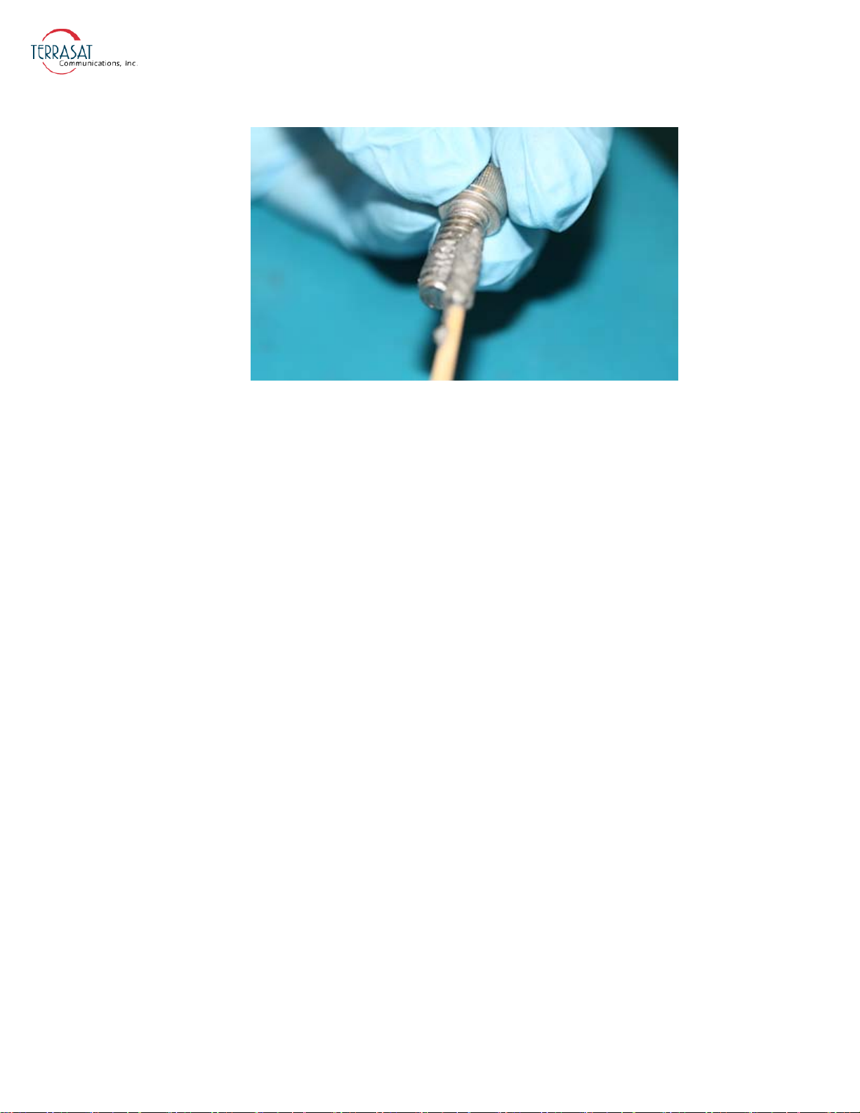
Figure 3.6
Applying the Anti-Seize Lubricant
4. Spread the lubricant to a thin film without any lumps.
5. Reassemble the parts using normal torque values.
6. Wipe off any excess material with a disposable towel.
Waveguide Connections
If necessary, connect a section of flexible waveguide between the orthogonal mode
transducer (OMT) transmit port and the IBUC Tx RF output (or optional Rx reject
filter). The waveguide should be attached to the antenna feed according to the
manufacturer’s instructions. Use proper gasketing methods to prevent water entry and
subsequent damage.
3-18 | IBUC 2, IBUC 2e, IBUC 2G, IBUC R Operations Manual: Installation
Page 67
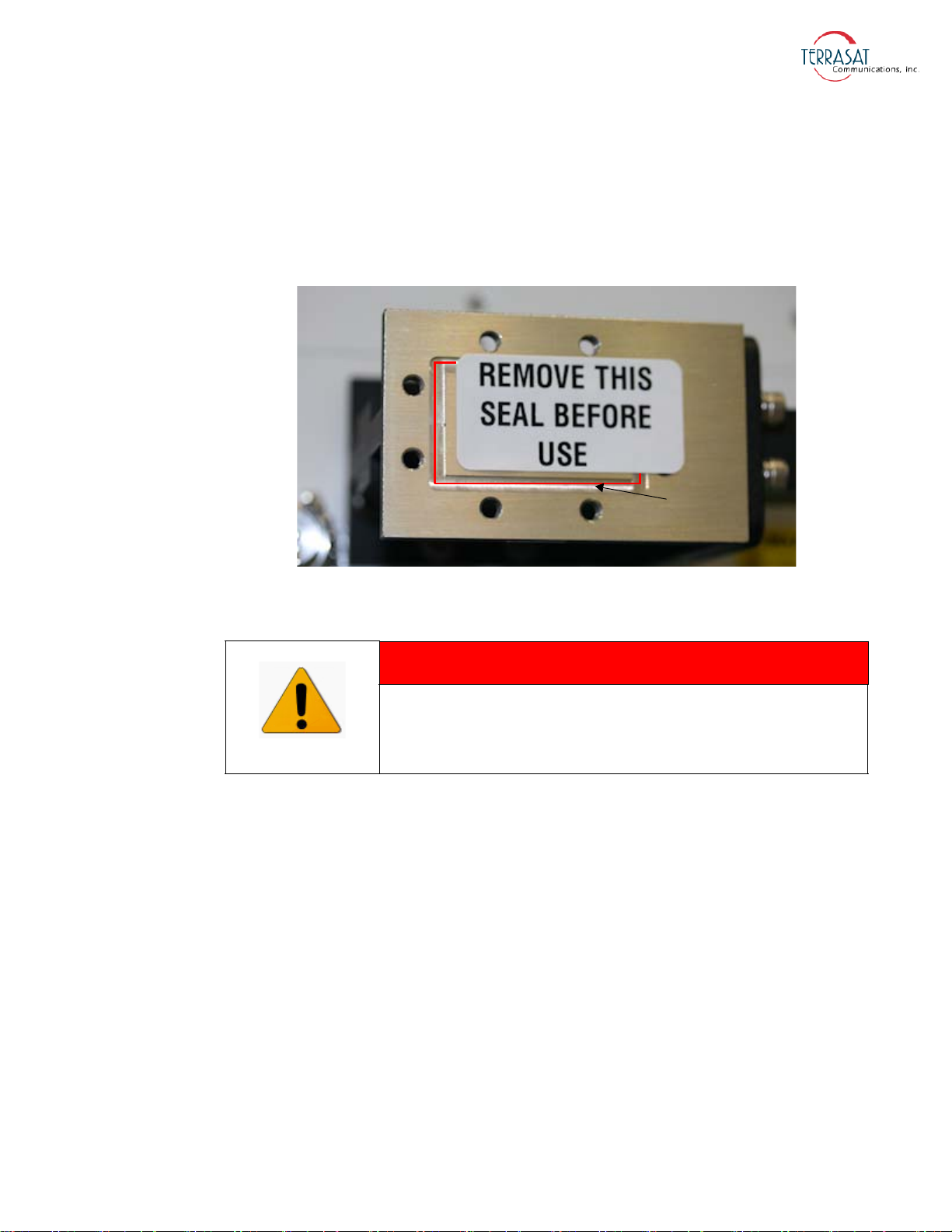
Note:
Channel for
Waveguide Gasket
During installation, be sure to remove the sticker shown in Figure 3.7 that covers the
waveguide flange. The sticker itself does not create a pressure window and will allow
moisture to enter the waveguide. Also be sure to install the waveguide gasket into the
channel identified in Figure 3.7 to ensure a good seal between surfaces. Do not re-use
old gaskets.
Note:
Figure 3.7
Waveguide Label and Channel for Gasket
WARNING
The output of the IBUC is microwave power. Never
look into the waveguide or put your head into the
path of the beam that goes to the satellite.
Typical Configuration Without an Interface Unit ( IFU)
While there are many possible configurations, Figure 2.7 on page 2-22 illustrates a
typical configuration for DC-powered low power IBUC 2e models.
A unit that is powered via coaxial cable is considered “low power.”
To configure the IBUC 2e without an IFU,
1. Connect the IFL coaxial cable between the Tx output from the modem and the Tx
input connector J1 on the IBUC 2e.
2. Connect a coaxial cable between the LNB (Rx output) and the modem’s L-band
Rx input.
3. Connect the M&C cable between the M&C port on the IBUC 2e and the
appropriate M&C or LAN connection
General Requirements | 3-19
Page 68

Note:
Use the J2 port if you are using RS232, RS485, or a Form-C relay for monitor and
control purposes.
Use the J4 port if you are using Ethernet for monitor and control purposes.
4. Connect the DC cable between the DC output connector on the power supply and
the DC input connector J3 on the IBUC 2e.
5. Connect the AC cable between the AC input on the power supply and the AC
power source.
Typical Configuration With an Interface Unit (IFU)
The configuration for DC-powered high power IBUCs is illustrated in Figure 2.8 on
page 2-23.
To configure the IBUC with an IFU,
1. Connect the IFL coaxial cable between the Tx input connector J1 on the IBUC and
the Tx output connector J2 on the IFU.
2. Connect a coaxial cable between the Tx input connector J1 on the IFU and the Tx
L-band output on the modem.
Note:
3. Connect a coaxial cable between the Rx output on the LNB and the Rx input
connector J4 on the IFU.
4. Connect a coaxial cable between the Rx output connector J5 on the IFU and the
modem’s L-band Rx input.
5. Connect the M&C cable between the M&C port on the IBUC and the appropriate
M&C or LAN connection.
Use the J2 port if you are using RS232, RS485, or a Form-C relay for monitor and
control purposes.
— or —
Use the J4 port if you are using Ethernet for monitor and control purposes.
6. Connect the DC cable between the DC output connector J2 on the outdoor PSUI,
as appropriate, and the DC input connector J3 of the IBUC. Low-power units can
be supplied from the modem or from the IFU through the coaxial cable to the
IBUC.
7. Connect the AC cable between the AC input connector J1 of the PSUI and the AC
power source.
3-20 | IBUC 2, IBUC 2e, IBUC 2G, IBUC R Operations Manual: Installation
Page 69
Typical Configuration With an AC-powered IBUC But Without an IFU
Figure 2.9 on page 2-24 illustrates a typical configuration for AC-powered IBUCs.
To configure an AC-powered IBUC:
1. Connect the IFL coaxial cable between the Tx output from the modem and the Tx
input connector J1 of the IBUC.
2. Connect a coaxial cable between the Rx output of the LNB and the modem’s
L-band Rx input.
3. Connect the M&C cable between the M&C port on the IBUC and the appropriate
M&C or LAN connection.
Note:
Use the J2 port if you are using RS232, RS485, or a Form-C relay for monitor and
control purposes.
— or —
Use the J4 port if you are using Ethernet for monitor and control purposes.
4. Connect the AC cable between the AC input connector J3 on the IBUC and the AC
power source.
Basic System Alignment
The following sections outline the procedure for setup and alignment of an earth
station. Before you align the ODU, the antenna should be set to the desired azimuth
and elevation settings per the manufacturer’s instructions.
Ensure that the IBUC Tx output power is disabled to prevent accidental transmission
interference with adjacent satellite or transponders before attempting to align or
perform any other operation involving the ODU. Before attempting any signal
changes, carefully evaluate the possible effects of the transmitted signal.
CAUTION
The IBUC must not transmit until alignment and any
necessary adjustments are complete.
Setting the Tx and Rx Frequencies
All transmit and receive frequencies are set in the modem.
If using a direct connection to an L-band modem, follow the manufacturer’s
instructions for setting the transmit and receive frequencies.
General Requirements | 3-21
Page 70
Receive L-band Output Measurements
To check the receiver,
1. Ensure that 15 VDC to 24 VDC (LNB Bias) is present at the modem or IFU Rx
input.
2. Use a spectrum analyzer to ensure that the 10 MHz reference signal is present at
the modem or Rx input of the IFU.
WARNING
DC power will be present on the cable. Terrasat
recommends the use of a DC block when using a
spectrum analyzer
3. Connect the LNB to the demodulator’s Rx input by attaching the coaxial cables
from the Rx L-band output on the LNB to the demodulator’s Rx L-band input port.
When configured with the IFU, connect the IFU Rx output connector J5 to the
demodulator’s Rx L-band input port and connect the LNB to the IFU Rx input by
attaching the coaxial cables from the Rx L-band output on the LNB to the Rx input
port J4 on the IFU.
T ransmit Power Alignment
Trans mit L- ba nd Input Adjustment with Modem or Converter
WARNING
DC power might be present on the cable. Terrasat
recommends the use of a DC block when using a
spectrum analyzer
To set the power level of the modulator output,
1. Use a spectrum analyzer to measure the power level of the L-band signal at the
output of the coaxial cable that connects to the IBUC at the Tx L-band connector
J1.
2. Use the level adjust mechanism of the modem or converter to increase or decrease
the power level. Adjust to reach a level of –30
to reach rated power at p1dB over frequency and temperature with -30
input when the attenuator is set to minimum attenuation.) For some modems and
shorter cable runs, it is not possible to reach –30
in the IBUC may be used instead.
dBm. (All IBUC units are designed
dBm at the
dBm. In this case, the attenuator
3-22 | IBUC 2, IBUC 2e, IBUC 2G, IBUC R Operations Manual: Installation
Page 71

3. Check that the 10 MHz reference signal is present and within the range of +5 dBm
though –12 dBm.
Note:
The IBUC 2, IBUC 2e, IBUC 2G, and IBUC R require a 10 Mhz reference signal
to operate. Check the model number of your IBUC to determine whether an external
10 MHz signal is required.
4. Disconnect the spectrum analyzer from the coaxial cable.
Tr ansm it RF Output Adj ustme nt with Modem or Converter (70 MHz to L-band)
To adjust the power level of the IBUC transmitter output,
1. Connect a waveguide-to-coaxial adapter and a 40 dB high-power attenuator to the
IBUC waveguide output.
2. Ensure that DC power to the IBUC is applied in the proper voltage range.
(Depending on your setup, this could be through the coaxial cable or through the
J3 connector.)
3. Connect the Tx L-band input signal to the Tx L-band connector J1 on the IBUC.
4. Enable the Tx signals in the modem or converter and the IBUC.
5. Measure the RF output with a power meter connected to the attenuator attached at
the waveguide output. For accuracy, measure pure carrier (that is, continuous wave
or CW) and the frequency allotted to you by the satellite network operations center
(NOC).
Note:
6. If the modem still has available range, use the level adjust mechanism to reach the
designated power level. If there is no available range, use the attenuation setting on
the IBUC instead.
To set attenuation on IBUC, you first need to establish communication with the
IBUC. For more information about the various M&C interfaces you can use to
establish communication, see
Chapter 5, Monitor and Control Features.
7. If using a satellite modem, adjust the RF output to the designated power level
(provided by the satellite network operations center or its engineering staff) with
the L-band output (modem) level adjust mechanism.
8. Disable the Tx signal in the modem or converter.
9. Disconnect the Tx L-band input signal.
10. Remove the waveguide-to-coaxial adapter and install the transmit waveguide
section to the antenna transmit feed.
11. Once the transmit input and output power levels have been set, begin transmitting
by connecting the Tx L-band input signal to the J1 connector on the IBUC and
enabling the Tx in the modem or converter.
12. Under the guidance of NOC staff, fine-adjust the transmit power for the desired
down link margin at the receiving station by adjusting the Tx L-band output level
General Requirements | 3-23
Page 72

adjust (modem or converter output) or by adjusting the gain of the IBUC by setting
the Tx attenuator.
Final Checks
To ensure reliable operation, inspect the system for crimped or pinched cabling. Make
sure that all connections are secure and sealed. Once the system has been aligned and
is operating satisfactorily, the IBUC will require infrequent maintenance.
3-24 | IBUC 2, IBUC 2e, IBUC 2G, IBUC R Operations Manual: Installation
Page 73

This chapter describes general operation of the IBUC 2, IBUC 2e, IBUC 2G, and
IBUC
Introduction
After the IBUC has been mounted and connections verified, the antenna must be
aimed towards the appropriate satellite. Follow the antenna manufacturer’s
instructions, using the coordinates (azimuth, elevation, and polarity) provided by the
satellite operator. Do not transmit until you have received authorization—including a
transmit power level—from the satellite network operations center (NOC) staff.
R.
C HAPTER
C
HAPTER
4
O
PERATIONS
St art-up Checklist
The IBUC leaves the factory preconfigured for operation; however, you can fine-tune
its settings for your particular needs.
Prior to start up, verify the following:
• Transmit/Receive frequencies
All transmit and receive frequencies are set using the modem. Follow the modem
manufacturer’s instruction.
• Cable connections
Ensure that all of the external cables between the IBUC and other equipment are
seated correctly and that there are no breaks or cracks, no sharp bends, pinch
points nor flattened sections in the cables.
•Power
Ensure that the IBUC is receiving power, Power can come via the modem, an
external power supply, or from AC mains.
Page 74

If power is supplied by the modem, ensure that the modem provides the correct
DC voltage and the DC power has been enabled.
•10 MHz reference signal
Verify that the 10 MHz reference signal is present. Some IBUC models have an
internal 10 MHz reference signal. If this option is not available, a 10 MHz
reference signal supplied on the IF cable from the modem (or an IFU) is required.
Turning On the IBUC
To turn on the IBUC 2, IBUC 2e, IBUC 2G, or IBUC R,
1. Connect the L-band input cable (J1), the M&C cable (J4), and the power cable (J3)
2. Apply power to the IBUC.
3. The Power LED on the side of the unit next to the J4 connector lights up.
A flashing green light indicates that the IBUC is operating normally.
A red light indicates only that a fault (or alarm) has occurred. (A flashing red light
indicates a minor alarm and a solid red light indicates a major alarm.)
4. Allow the unit to warm up for approximately 15 minutes before operating the
transmitter module. This will assure stable gain and power.
Setting Operating Parameters
To set operating parameters, the IBUC must be connected to a terminal (for example,
a hand-held terminal, a terminal emulator such as HyperTerminal, or the embedded
Web pages via a PC). The most user-friendly way to connect to the IBUC is by using
the embedded Web pages. Connect the IBUC to the Ethernet port of a PC by using a
TCP/IP cable assembly (such as the one depicted in Figure G.2 on page G-3).
1. Establish communication with the IBUC by using the steps provided in Appendix
C, Web Pages.
2. Navigate to the Transmit Configuration tab as shown on page C-13.
3. Set the Tx Output by selecting whether the unit is actively transmitting or not.
Options include:
• Enable
• Disable
When the Tx Output is set to Disabled, the Tx Output level displayed on the Sensor
Tab (shown on page C-11) reads -99.0 dBm. This is not the actual reading.
When conditions cause the automatic shut-off of the Tx Output signal, the Tx
Output is muted and the Tx Output level displayed on the Sensor Tab (shown on
page C-11) reads -96.0 dBm. This is not the actual reading.
4-2 | IBUC 2, IBUC 2e, IBUC 2G, IBUC R Operations Manual: Operations
Page 75

Note:
This setting can be overridden by the modem. The modem will send commands
(data) to the IBUC and no single port is given priority. This continues as long as
both the IBUC and the modem use Legacy Binary mode. If the IBUC is set to
ASCII mode, communication between the modem and the IBUC ceases due to the
differences in command formats.
4. Set the Power Monitor Frequency that is used to set at which frequency you are
operating. The factory default values in Table C.1 on page C-14 are listed
according to the model number of the IBUC.
Note:
To ensure accurate readings, you must set the actual operating frequency.
Example: If, according to your Satellite NOC, your allocated frequency is
6400 MHz, set the Power Monitor Frequency to 6400 MHz. Do not use the factory
default value unless that is your actual operating frequency.
5. Set the Power Read Mode.
Options include:
• Burst
• Continuous Wave
6. Set the Gain Mode.
Options include:
• Open
Open is the gain obtained when there is no feedback in the measuring loop.
• AGC (Automatic Gain Control)
The IBUC continuously monitors input and output levels. When AGC is
enabled, the gain of the system is maintained at a constant level by an internal
algorithm. Gain is the difference between output power and input power.
Note:
• ALC (Automatic Level Control)
Similar to the AGC system, when ALC is enabled the gain is adjusted when
changes are detected in order to maintain a constant output level.
The IBUC has an internal temperature compensation feature that minimizes gain
variations due to to changes in temperature. This feature is configured at the factory
and requires no user input. For specific information about your particular model
IBUC, see the datasheets in Appendix G, Component Specifications and Reference
Drawings.
Start-up Checklist | 4-3
Page 76

Setting the Tx Frequency (L-band)
Changing the L-band frequency will cause a change to the RF frequency.
To set the L-band frequency,
1. Establish communication with the IBUC by using the steps provided in Appendix
C, Web Pages.
2. Navigate to the Information tab as shown on page C-6.
3. Verify the data in the Band Inversion field.
4. Calculate the IF frequency by using the following formulas:
IF = RF - LO Non-inverted/Low side
IF = LO - RF Inverted/High side
Note:
Note:
RF and LO frequencies for various bands are provided in Table 2.1 on page 2-3.
Setting Alarm Thresholds
Although the IBUC will function using the factory-configured settings, by setting high
and low level thresholds for the Tx Input/Output you can access more information
about events such as power fluctuations that might trigger an alarm.
Alarms will be generated when the input and output amplitudes fall outside of the
threshold ranges. For this reason, Terrasat recommends that when you have reached
the proper input and output settings for your budget, you narrow the threshold ranges
for alarms.
1. Set the Tx Input High/Low Thresholds.
The IBUC leaves the factory with a default range of -15 dBm to -60 dBm.
Example: After observing the unit, you determine that the IBUC operates
consistently at -37 dBm. Although the threshold range is 45 dB, that range is too
wide for everyday use. Instead consider setting the input thresholds at ±3
would make the high level threshold -34
dBm and the low level threshold -40 dBm.
You will receive an error message if the input level exceeds the threshold range.
dB; this
2. Set the Tx Output High/Low Thresholds.
When you set up your system and the Tx Output reaches its budgeted level, Terrasat
recommends that, instead of the (P1dB - 20 dB) to (P1dB + 1 dB) threshold range
that is the default, you narrow the range between the high and low thresholds to
±3 dB.
Example: After observing the unit, you determine that the output level operates
consistently at 32 dBm. Although the threshold range is 21 dB, that range is too
wide for everyday use. Instead consider setting the output thresholds at ±3
would make the high level threshold 35
4-4 | IBUC 2, IBUC 2e, IBUC 2G, IBUC R Operations Manual: Operations
dB; this
dBm and the low level threshold 29 dBm.
Page 77

Note:
You will receive an error message if the output level exceeds the threshold range.
3. Verify your settings against the readings on the Info Page as shown on page C-6 of
Appendix C, Web Pages.
Configuring Alarm States
The IBUC offers flexibility with the levels of alarms produced when user-specified
thresholds are exceeded.
1. Consider which alarms to configure. Table 5.1 on page 5-4 contains the default
alarm configuration.
2. Navigate to the Alarm Configuration tab shown on page C-23 of Appendix C,
Web Pages.
3. Use the drop-down menus to mark an alarm as a major event, a minor event, or to
disable it.
4. Click Save Settings when you have completed your inputs to ensure that your
settings are saved. If you do not click Save Settings, your changes will not be
implemented.
Configuring ALC/AGC
The IBUC 2, IBUC 2e, IBUC 2G, and IBUC R offer two methods of ensuring
consistent signal levels: automatic level control (ALC) and automatic gain control
(AGC).
ALC
When enabled, the Automatic Level Control (ALC) circuitry in the IBUC monitors
output levels and adjusts the gain to maintain a consistent output for input signal
variations. If a signal level is consistently below the predetermined target level, the
ALC will cause the gain to be increased until the target level is reached. If a signal
level exceeds the target level, the ALC will decrease the gain.
To enable ALC,
1. With the Gain Mode set to “Open” and the Tx Input and Tx Output Thresholds set,
monitor the Tx Output level in order to determine a baseline setting.
2. When the Tx Output Level reading is equal to the level that you want to maintain,
enable ALC by using any of the M&C interfaces.
The IBUC will now continuously self-monitor, increasing or decreasing the gain in
order to maintain a constant signal at the level you defined.
Note:
The Tx Output Level is “captured” when ALC is enabled.
Start-up Checklist | 4-5
Page 78

AGC
When enabled, the Automatic Gain Control (AGC) circuitry in the IBUC maintains
the gain constant and equal to the target gain that was established when AGC was
enabled.
Gain control settings can drift with time or temperature changes. You can reset the
Gain Control function (when reset, the Gain Control returns to mid-range or 0.0).
Terrasat units enable you to offset the target by using the attenuation control without
having to first disable the ALC or AGC.
Example: Set the output power level to 40 dBm and enable ALC. From this point
forward, the ALC algorithm will maintain the output level at 40 dBm.
If you want to change the output level to 41 dBm, reduce the attenuation by 1 dB. The
target level will be updated automatically.
Configuring the External Mute
Pin N of the M&C interface connector has dual functionality: it functions as an alarm
input or an external mute.
External Mute
When the IBUC operates as a single thread IBUC, Pin N of the M&C interface
connector functions as an external mute. If it is not connected (left open), then
transmission is not muted. When Pin N is connected to Pin F (chassis ground),
transmission is muted.
To re-enable transmission, remove the Pin N connection to Pin F. Transmission will
now resume.
Alarm Input
When the unit is operating as part of a redundant IBUC system, the redundant
configuration is sensed automatically. In redundant systems, Pin N functions as an
alarm input where the alarm output of the A: side IBUC is connected to the alarm
input of the B:
side IBUC and vice versa.
For more information about the M&C interface connector, see System Cabling
Requirements on page 3-13.
4-6 | IBUC 2, IBUC 2e, IBUC 2G, IBUC R Operations Manual: Operations
Page 79

Common Errors
LED is Red
A red LED indicates only that a fault (or alarm) has occurred and does not necessarily
indicate that transmission has stopped. A flashing red light indicates a minor alarm and
a solid red light indicates a major alarm. You can communicate with the IBUC to
determine what is causing the fault, and then clear the fault condition.
1. Establish a connection with the IBUC 2, IBUC 2e, IBUC 2G, or IBUC R by using
any of the M&C interfaces described in Chapter 5.
2. View the Alarm Status Tab (shown on page C-8) to determine the current alarm.
You can also check the Sensor Tab (shown on page C-11) to determine which
reading caused the alarm, and then compare the readings with the threshold levels.
If necessary, adjust the threshold level(s).
When the fault is cleared, the LED should be flashing green.
No Power to the IBUC 2, IBUC 2e, IBUC
If the Power LED is off or not turning on at all, the IBUC is probably not receiving
power.
Restore power to the IBUC by
• If the IBUC is powered by the modem, verifying that the modem is working
properly.
• Checking that the modem is receiving power (that is, the modem power cord is
plugged in) and that DC power to the IBUC is enabled.
• Checking that all cable connections are solid.
• Checking that the power supply is functioning or that AC mains has the proper
voltage.
• Checking the disconnect devices such as the circuit breaker.
• Checking the fuses.
• For DC-powered IBUCs, the fuses are in the power supply.
• For AC-powered IBUCs, the fuses are in the IBUC.
2G
, or IBUC
R
Fuses are 5x20 mm time-lag glass body cartridge type.
Common Errors | 4-7
Page 80

WARNING
Before applying power to the unit, ensure
that that waveguide output is properly
terminated. Failure to do so could lead to
serious personal injury, excessive RF
radiation levels, and equipment damage.
Time St amp Data is Incorrect
The time stamp on the alarm log is incorrect after the IBUC has lost power for an
extended period. You can set the system date and time by using the hand-held terminal
(see Appendix D) or the System Configuration tab of the embedded Web pages (see
Appendix C).
When using a Web browser to access the embedded Web pages, the time stamp
information displayed differs slightly by Web browser. The time stamp displayed on
the Web pages records the time that the page was created and is based upon the system
time of the computer, and not the IBUC.
Satellite Network Operations Center Doesn’t Recognize Signal
The IBUC 2, IBUC 2e, IBUC 2G, or IBUC R appears to be transmitting a signal, but
the satellite network operations center (NOC) cannot identify your carrier.
To determine whether your settings are correct,
1. Verify that your frequency is within the bandwidth slot that was allocated to you.
2. Determine whether the IBUC operates with the LO on the low side or the high side
of the frequency that was allocated to you.
3. Check the signal mix. Remember that low-side is non-inverting and high-side is
inverting.
4. Use the following formulas to calculate IF frequency
low side IF = RF - LO Non-inverting
high side IF = LO - RF Inverting
The LO for each IBUC band is found in Table 2.1 through Table 2.4.
5. Check the Tx output level.
When Tx output power is disabled, the Tx output level will read -99.0 dBm. This is
not an actual power reading; rather it indicates the loss of power.
When conditions cause the automatic shut-off of the Tx output signal, the Tx output
4-8 | IBUC 2, IBUC 2e, IBUC 2G, IBUC R Operations Manual: Operations
Page 81

level will read -96.0 dBm. This is not an actual power reading; rather it indicates the
automatic shut-off of power.
T ransmit Power in Saturation
The IBUC, at minimum attenuation, makes rated power at -30 dBm input. Operating
the IBUC at higher levels will result in spectral distortion and high intermodulation
levels. Terrasat recommends operating with power back-off levels sufficient to meet
the spectral density mask.
To avoid signal saturation,
1. Reduce input power from the modem.
2. Increase the attenuation setting of the IBUC.
Tx Input/Output Level V erification
To verify the Tx IF Input level,
1. Use the Sensor Tab of the embedded Web pages to check levels.
For more information about the Sensor Tab, see page C-11.
2. Compare the reading to your expected level.
The detector range is -55 dBm to -20 dBm.
To verify the Tx RF Output level,
1. Use the Sensor Tab of the embedded Web pages to check levels.
For more information about the Sensor Tab, see page C-11.
2. If your reading does not match your expected level, first verify that the IBUC 2,
IBUC
2e, IBUC 2G, or IBUC R is receiving the proper input level.
3. If the input is at the correct level, use the Transmit Configuration Tab of the
embedded Web pages to modify the attenuation to set the output to the expected
level. The Transmit Configuration Tab is shown on
page C-13.
4. If, after setting the output to your expected level, you are still having transmission
problems, check the flexible waveguide and antenna feed for obstructions. Also
check the alignment of the antenna.
Common Errors | 4-9
Page 82

4-10 | IBUC 2, IBUC 2e, IBUC 2G, IBUC R Operations Manual: Operations
Page 83

This chapter describes the various monitor and control (M&C) features and functions
that the IBUC
Introduction
C
HAPTER
5
M
ONITOR AND
2, IBUC 2e, IBUC 2G, and IBUC R offer.
C HAPTER
C
ONTROL
F
EATURES
You must first establish a communication link with the IBUC to be able access any of
the M&C interfaces.
M&C Interfaces
The IBUC 2, IBUC 2e, IBUC 2G, and IBUC R offer the following M&C interfaces:
• RS232
• Hand-held terminal
• Multifunction LED
• Frequency Shift Keying Modem Interface
• RS485
• Ethernet
RS232
No additional configuration of the IBUC is required for proper RS232 operation. The
RS232 port uses ASCII protocol and a fixed baud rate of 9600, 8 stop bits, no parity,
no flow control, and one stop bit for communication.
Page 84

To initiate an RS232 session,
1. Connect a 19-pin to DB9F cable between the computer and the IBUC.
Figure G.1 on page G-2 contains a drawing for fabricating a cable.
2. Activate a terminal emulation program such as HyperTerminal.
For information about how to connect using HyperTerminal, see Appendix B,
Using HyperTerminal.
3. Type four grave accent marks (e.g., ` ` ` ` ), and then press Enter.
Although the default mode for the IBUC is RS232, typing the four grave accent
marks upon activating a terminal emulation program ensures that the unit is in
RS232 mode.
4. Type the password command CPE=1234 and then press Enter.
You can now use the ASCII commands described in Appendix F, ASCII Com-
mand/Response Structure to configure and monitor the IBUC.
Note:
The password entered in Step 4 is the factory default password of 1234. If you
have changed the password, type that value instead.
The RS232 port is shared with the hand-held terminal.
Hand-held Terminal
The hand-held terminal (HHT) shown in Figure 5.1 is an optional item that can be
used to access the IBUC 2, IBUC 2e, IBUC 2G, and IBUC R via the J2 connector for
local monitor and control. No additional configuration of the IBUC is necessary.
5-2 | IBUC 2, IBUC 2e, IBUC 2G, IBUC R Operations Manual: Monitor and Control Features
Page 85
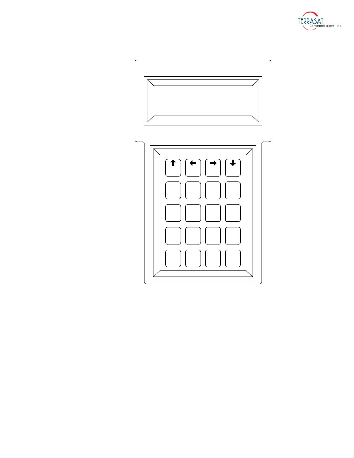
Figure 5.1
F1 F2 F3 F4
1 23
654
987
.
0
SPACE ENTER
BKSP
NO
YES
To activate the HHT,
1. Connect the supplied cable to the J2 connector on the IBUC and plug the RJ-11
connector into the HHT.
Hand-held Terminal
2. When a flashing cursor is seen in the upper left of the HHT screen, press the
decimal key four times (that is, “. . . .”).
The login screen shown in Figure D.1 on page D-2 will appear.
3. Type the password.
The default password is 1234. If you have changed the password, type that value
instead.
The HHT is now ready to accept commands.
M&C Interfaces | 5-3
Page 86
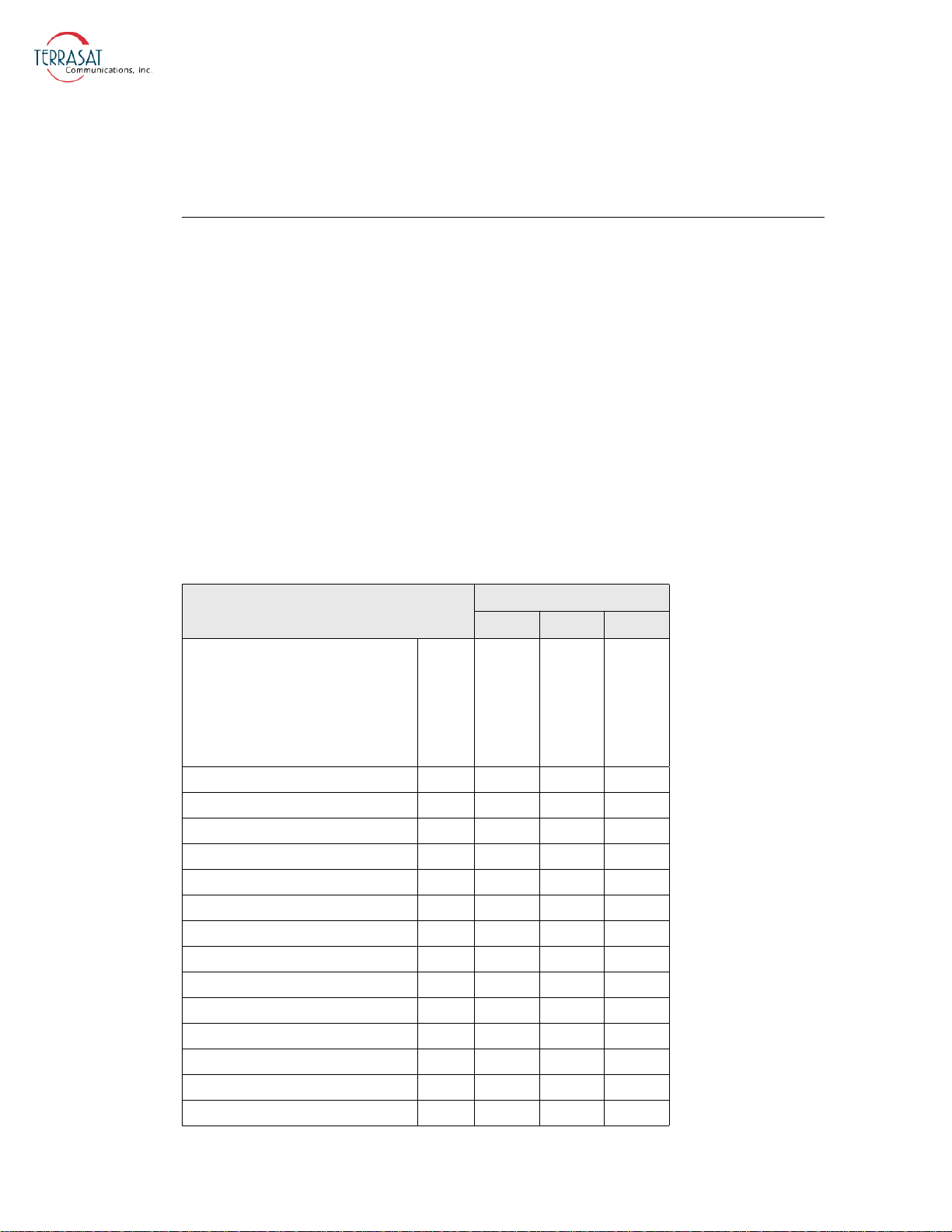
Additional information about the HHT is in Appendix D, Hand-held Terminal Menu
Tree.
Multifunction LED
The multifunction LED is mounted on the IBUC 2, IBUC 2e, IBUC 2G, and IBUC R
housing and provide visual indications of IBUC status. LED colors and modes are as
follows:
• Flashing Green - No alarms
• Flashing Red - Minor alarm being reported
• Steady Red - Major alarm being reported
Certain alarms are configurable meaning that you define them as major or minor
alarms when thresholds you set are exceeded. Major alarms will cause relay closure
(Form-C). The alarms shown in Table 5.1 are the factory default configuration.
Thresholds for alarms that are user configurable can be set by using any of the M&C
interfaces described in this chapter.
Table 5.1
Tx Alarms
DRO out of lock No X
Tx Output Level High Yes X
Tx Output Level Low Yes X
Tx Input Level High Yes X
Tx Input Level Low Yes X
Temperature Alarm Yes X
Tx Simulated Fault No X
10 MHz Reference Fault No X
Input Voltage Out of Range No X
Switch Fault No X
Input Current Out of Range No X
AGC/ALC Target Out of Range No X
AGC/ALC Out of Range No X
AGC/ALC Not Settled No X
Default Alarm Configuration
Alarm State
Major Minor None
User
Configurable
Solid RED
Flashing Red
Log Only
5-4 | IBUC 2, IBUC 2e, IBUC 2G, IBUC R Operations Manual: Monitor and Control Features
Page 87
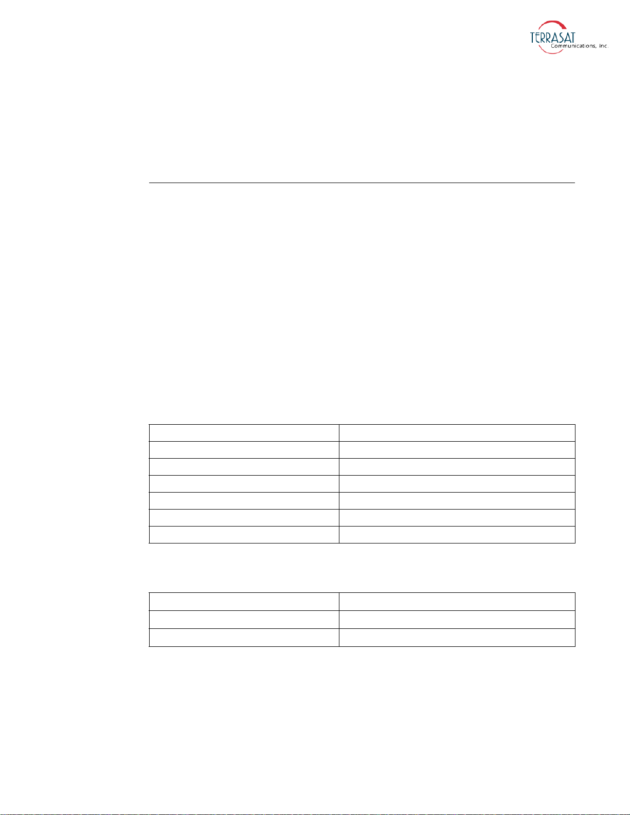
You can disable the multifunction LED. Use the ASCII command “CLE” described in
Appendix F, the “External LED” command described in Appendix E, the hand-held
terminal described in Appendix D to disable the LEDs, or the System Configuration
Tab of the Web pages described in Appendix C.
Frequency Shift Keying (FSK) Modem Interface
Several modem brands have the capability to communicate with an IBUC using an
FSK signal multiplexed onto the IF output connector with the Tx IF signal and the
10 MHz reference signal. The default configuration for the IBUC is RS485/FSK
Mode 1 which enables compatible modems to use “Legacy Binary” mode to
communicate with the IBUC. The IBUC is also capable of FSK communication using
ASCII mode but requires a modem compatible with this method. Refer to the
modem’s documentation for more information about commands and procedures for
FSK communication with the IBUC.
FSK and RS485 are tied together by the mode of operation (Legacy Binary or ASCII).
Once the mode is selected, both FSK and RS485 will work in the same mode. FSK and
RS485 also share a common address. The message formats for both FSK and RS485
are the same. Transmitter link specifications are detailed in Table 5.2 and receiver link
specifications are detailed in Table 5.3.
Table 5.2
Frequency
FSK Deviation
Deviation Tolerance
Output Level
Output Impedance
Start Tone
Start Tone Time
Table 5.3
Locking Range
Input Impedance
Input Sensitivity
Transmitter Link Specifications
650 KHz ±5%
±60 KHz nominal (+60 KHz mark)
±50 KHz minimum; ±70 KHz maximum
-5 dBm to -15 dBm
50
710 KHz
10 ms
Receiver Link Specifications
±32.5 KHz
50
-15 dBm
FSK data is transmitted at 9600 baud with 8 data bits, no parity, no flow control, and
one stop bit.
M&C Interfaces | 5-5
Page 88

Synchronization is maintained by the following method:
1. Once a character is received and the inter-character time exceeds 20 ms, then the
link will reset.
The IBUC is capable of responding to messages at a rate of one every 20 ms.
2. If the IBUC does not respond within the maximum response time, the command
should be cyclically repeated.
Note:
This synchronization method is true only for Legacy Binary mode (not ASCII).
RS485
The RS485 interface is intended primarily as a network management system (NMS)
interface accessed by an NMS program. You can also access the RS485 interface with
the host computer by using the host computer’s on-board RS485 card or by using an
external RS232-to-RS485 adapter. You can communicate with the IBUC across
RS485 through ASCII or through the binary protocol known as “Legacy Binary.”
The RS485 interface is a standard two-wire interface (DATA+ and DATA-). The baud
rate is programmable to 1200, 2400, 4800, 9600, 19200, 38400, 57600, or 115200
baud. The data is transmitted asynchronously as 8 bits, no parity, no flow control, and
one stop bit.
To configure RS485, you will need to set the following:
• RS485 Address
• RS485 Delay
• RS485 Baud rate
• Legacy Binary or ASCII mode
You can configure RS485 by using any of the M&C interfaces described in this
chapter.
ASCII Mode
Because Legacy Binary is the default RS485 setting for the IBUC, you will need to
reconfigure the IBUC in order to use ASCII mode. You can specify ASCII mode by
using any of the M&C interfaces described in this chapter.
Communication requires an on-board RS485 card in the host computer. However, if
an external interface converter box is used to convert RS232 to RS485, a terminal
emulation program such as HyperTerminal will not function unless the interface
converter box is equipped with an automatic line turnaround capability. Otherwise, a
network management program is required to handle this handshaking requirement.
5-6 | IBUC 2, IBUC 2e, IBUC 2G, IBUC R Operations Manual: Monitor and Control Features
Page 89

In HyperTerminal, type the password command, and then press Enter. For example,
<001/CPE=1234 where <001/ is the address of the IBUC and 1234 is the default
password. When the > prompt re-appears, the IBUC is ready to accept commands.
ASCII Mode Command Format
Table 5.4 lists the differences between SET and GET commands in ASCII Mode.
Table 5.4
SET Commands GET Commands
Start of Packet: <
(ASCII code 60; 1 character)
Target Address: (4 characters) Target Address: (4 characters)
Address De-limiter: /
(ASCII code 47; 1 character)
Instruction code: (3 characters) Instruction code: (3 characters)
Code qualifier: =
(ASCII code 61 or 63; 1 character)
For a list of ASCII codes, see Appendix F.
Arguments: (n characters) —
End of Packet: Carriage Return
(ASCII code 13; 1 character)
ASCII Mode Command Format
Start of Packet: <
(ASCII code 60; 1 character)
Address De-limiter: /
(ASCII code 47; 1 character)
End of Packet: Carriage Return
(ASCII code 13; 1 character)
—
For GET Commands, the format is as follows:
<address/command[CR}
Example: <0001/COI{CR}
For SET Commands, the format is as follows:
<address/command=XXX[CR}
Example: <0001/CPE=1234{CR}
ASCII Mode Response Format
• Start of Packet: > (ASCII code 62; 1 character)
• Target Address: (4 characters)
• Address De-limiter: / (ASCII code 47; 1 character)
• Variable Length Data: (n characters)
M&C Interfaces | 5-7
Page 90
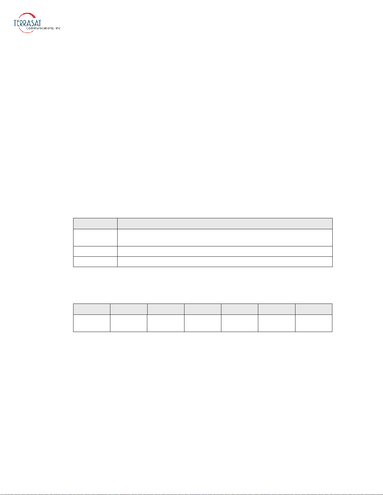
• End of Packet: Carriage Return (ASCII code 13; 1 character)
Example: >0001/{Variable Length Data}{CR}
Commands and values available in ASCII mode are provided in the command set in
Appendix F.
Legacy Binary Mode
Legacy Binary mode is the default RS485 setting for the IBUC. In Legacy Binary
Mode, using the BUCMON program that is included on the CD-ROM which
accompanies the unit is the simplest method of communicating with the IBUC. If you
do not have access to the BUCMON program, you will need to use a separate network
management program.
For the RS485 interface, the packet is encapsulated inside a data link layer packet
which has an address “header” byte and a checksum “trailer” byte. Table 5.5 contains
the packet format.
Table 5.5
Byte Description
1
2 through 6 Command or response packet data.
7 CHECKSUM: the sum of bytes should equal zero.
Packet Format
RS485 destination address of command. For responses, responder address is
shifted left by 4 bits.
Each transmitted command data packet consists of the seven bytes shown in Table 5.6.
Table 5.6
Byte 1 Byte 2 Byte 3 Byte 4 Byte 5 Byte 6 Byte 7
IBUC 2
Address
Data Packet Byte Configuration
Command Data Byte 1 Data Byte 2 Data Byte 3 Data Byte 4 Check Sum
Where
• Byte 1 contains the IBUC address that is being queried.
The IBUC will accept a command only if the first byte contains the appropriate
address.
• Byte 2 contains the major command.
See Appendix E for possible commands.
• Byte 3, Byte 4, Bye 5, and Byte 6 contain the specific command response values.
See Appendix E for possible command responses.
5-8 | IBUC 2, IBUC 2e, IBUC 2G, IBUC R Operations Manual: Monitor and Control Features
Page 91

• Byte 7 contains the algebraic sum of Bytes 1 through 6.
Commands are executed only if the checksum coincides.
For more information about response data packet configuration, see Appendix E,
Legacy Binary Command Message Structure.
Ethernet
Using Ethernet, you can communicate with the IBUC 2, IBUC 2e, IBUC 2G, or
IBUC R through Telnet (ASCII), the onboard Web server (HTTP), or through SNMP.
The IBUC uses a static IP addressing structure and does not support DHCP (Dynamic
Host Control Protocol).
The IBUC is configured at the factory, as follows:
IP Address 192.168.1.21
IP Gateway 192.168.1.1
Subnet Mask 255.255.255.0
Telnet Port 23
Note:
Note:
Your computer should have a static IP address on the same subnet as the IBUC. Using
a suitable cable, connect the computer to the J2 connector on the IBUC.
If an Ethernet hub is not used to connect to the IBUC, a crossover cable must be used.
However, most current Ethernet cards have an auto-sensing feature which enables the
use of a straight connect cable.
Determining the IP Address of Your IBUC
Follow these steps to determine the IP address of a unit that is not on the same subnet
as the host computer by using the Wireshark® network packet analyzer. Wireshark is
an open source project that also enables you to capture and interactively browse the
traffic running on a computer network.
To download Wireshark,
1. Open a Web browser window and navigate to the Wireshark website at
www.wireshark.org
M&C Interfaces | 5-9
Page 92
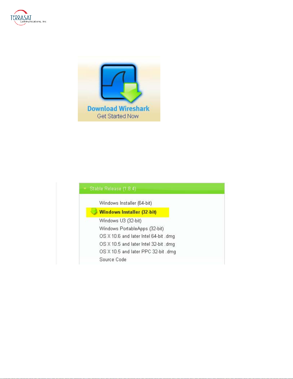
2. Double-click the Download Wireshark icon shown in Figure 5.2 to begin the
process.
Figure 5.2
Download Wireshark Icon
3. The Download page shown in Figure 5.3 appears. The software will automatically
sense whether your computer is running a 32-bit or 64-bit version of Windows.
Double-click the version that is highlighted to begin the installation process.
In Figure 5.3, a 32-bit verison of Windows was sensed and the 32-bit Windows
Installer is highlighted. Also, the release version number may differ from what
appears in the green bar in Figure 5.3.
Figure 5.3
Wireshark Release Version
4. An executable alert message similar to the one shown in Figure 5.4 appears. Click
Save File to begin downloading and then saving the Wireshark executable file.
5-10 | IBUC 2, IBUC 2e, IBUC 2G, IBUC R Operations Manual: Monitor and Control Features
Page 93
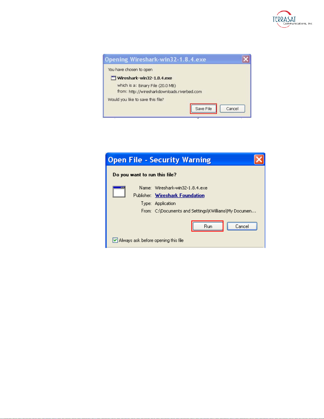
Figure 5.4
Executable Alert Message
5. When the files have downloaded, a window similar to the one shown in Figure 5.5
appears. Click Run to begin the Installation Wizard.
Figure 5.5
Open File Security Warning Message
6. The Installation Wizard begins with a welcome window similar to the one shown
Figure 5.6. Click Next.
in
M&C Interfaces | 5-11
Page 94
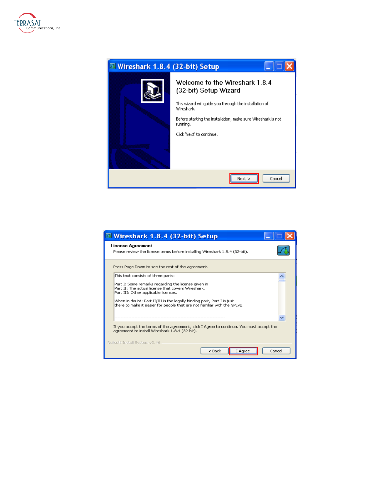
Figure 5.6
Installation Wizard Welcome
7. A window containing the license agreement similar to the one shown in Figure 5.7
appears. Click I Agree to continue the installation.
Figure 5.7
Wireshark License Agreement
8. A window containing a list of the various components available for installation
similar to the one shown in Figure 5.8 appears. Terrasat recommends keeping all
default values. Click Next.
5-12 | IBUC 2, IBUC 2e, IBUC 2G, IBUC R Operations Manual: Monitor and Control Features
Page 95
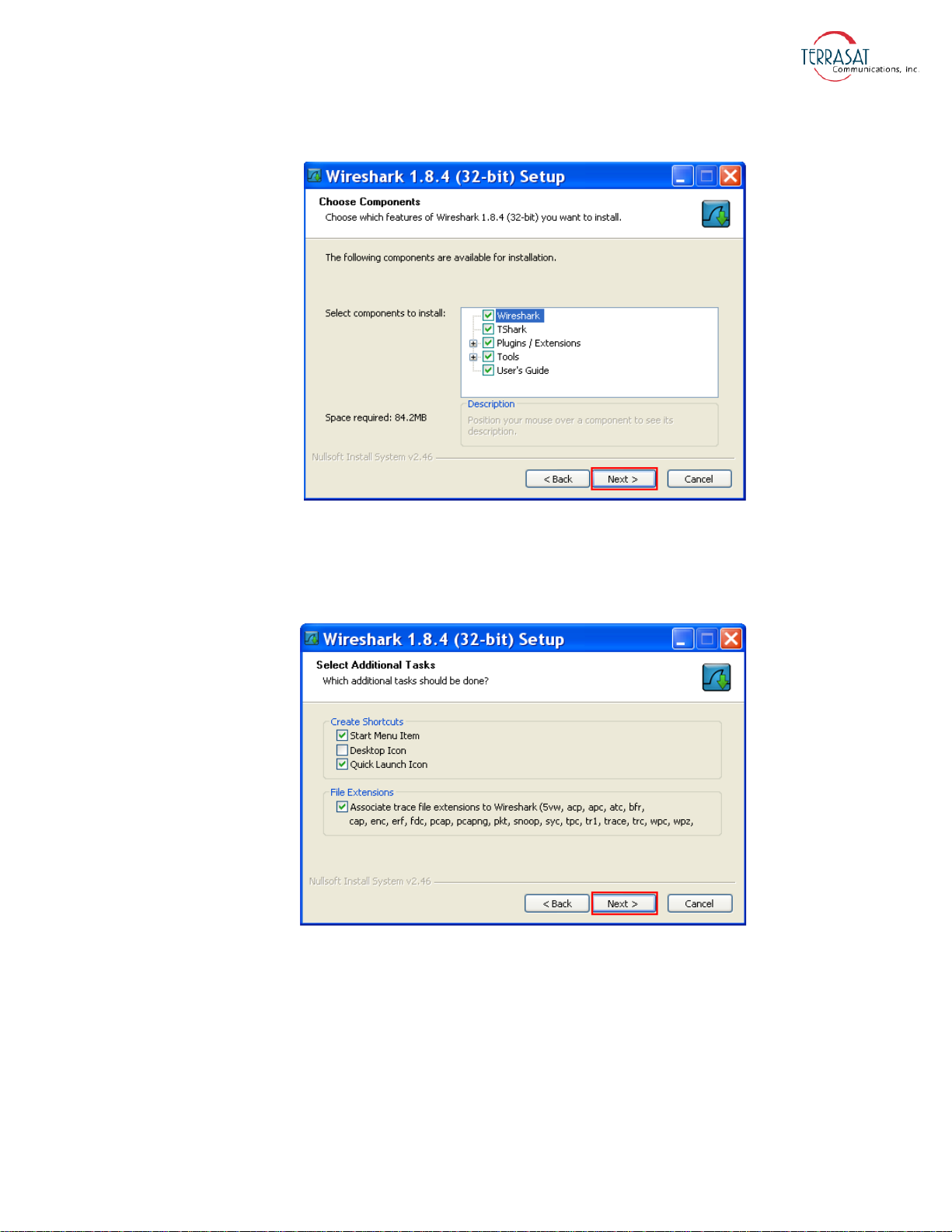
Figure 5.8
Choosing Wireshark Components
9. A window containing a list of the additional tasks available for installation similar
to the one shown in Figure 5.9 appears. Terrasat recommends keeping all default
values. Click Next.
Figure 5.9
Selecting Additional Wireshark Tasks
10. A window containing the location for installation similar to the one shown in
Figure 5.10 appears. Terrasat recommends keeping the default location. Click
Next.
M&C Interfaces | 5-13
Page 96
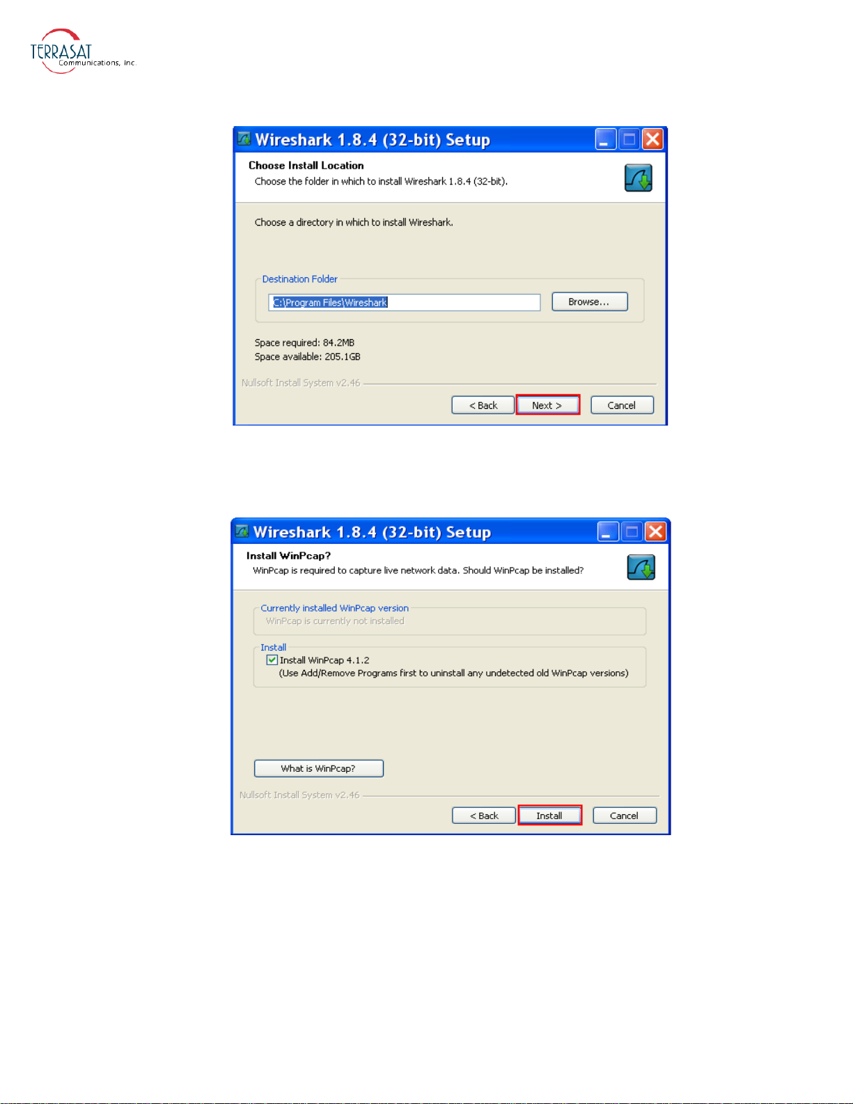
Figure 5.10
Choosing the Installation Location
11. A window asking if you want to install WinPcap similar to the one shown in
Figure 5.11 appears. WinPcap is required to capture live network data. Click Next.
Figure 5.11
Installing WinPcap
12. A window similar to the one shown in Figure 5.12 that contains the progress of the
installation appears.
5-14 | IBUC 2, IBUC 2e, IBUC 2G, IBUC R Operations Manual: Monitor and Control Features
Page 97
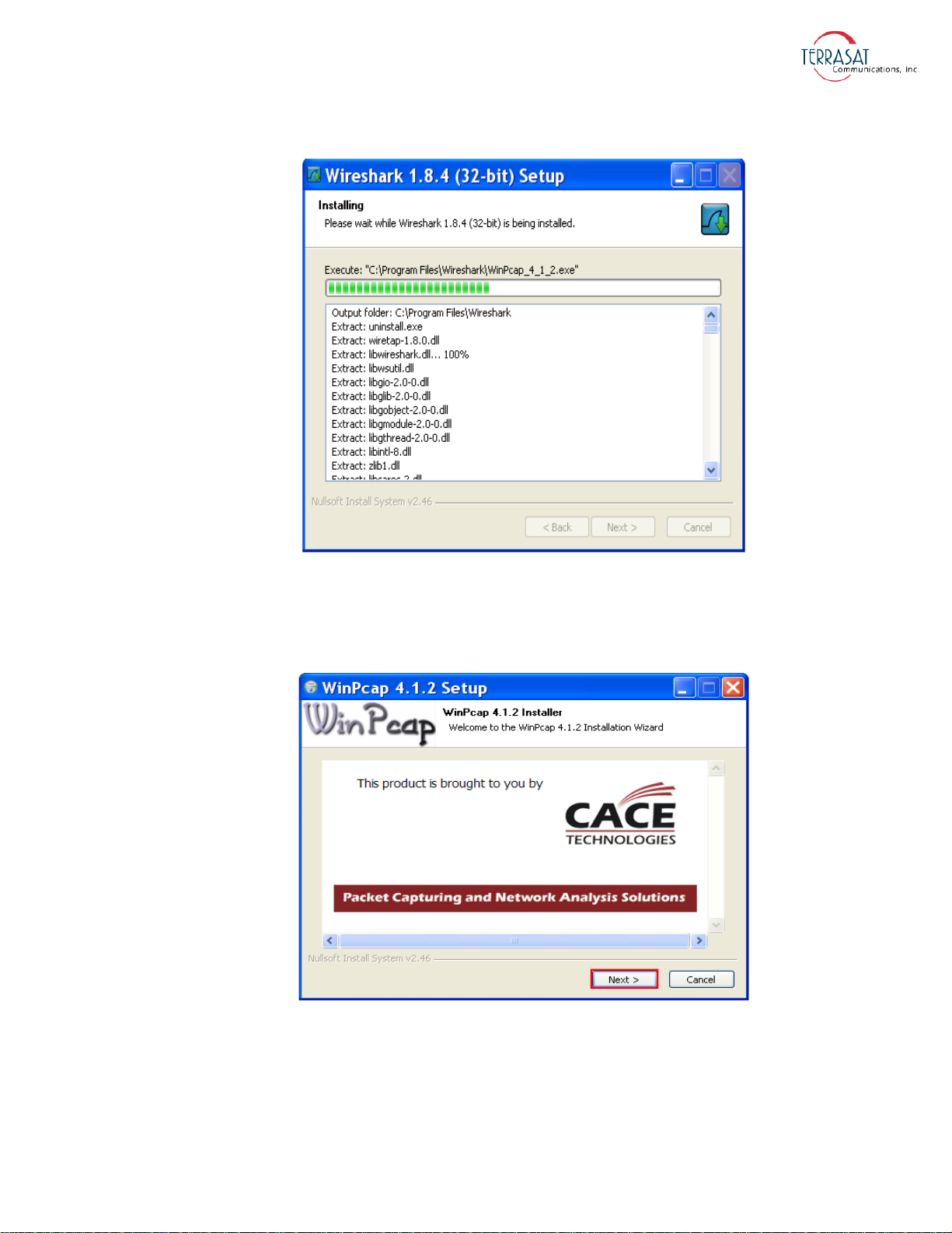
Figure 5.12
Installation Progress Bar
13. When the Wireshark installation is complete, a window similar to the one shown in
Figure 5.13 that contains the WinPcap Installer wizard appears. Click Next, and
then follow the on-screen prompts.
Figure 5.13
WinPcap Installer
14. Setup of Wireshark is complete when a window similar to the one shown in Figure
5.14 appears. Click Next.
M&C Interfaces | 5-15
Page 98
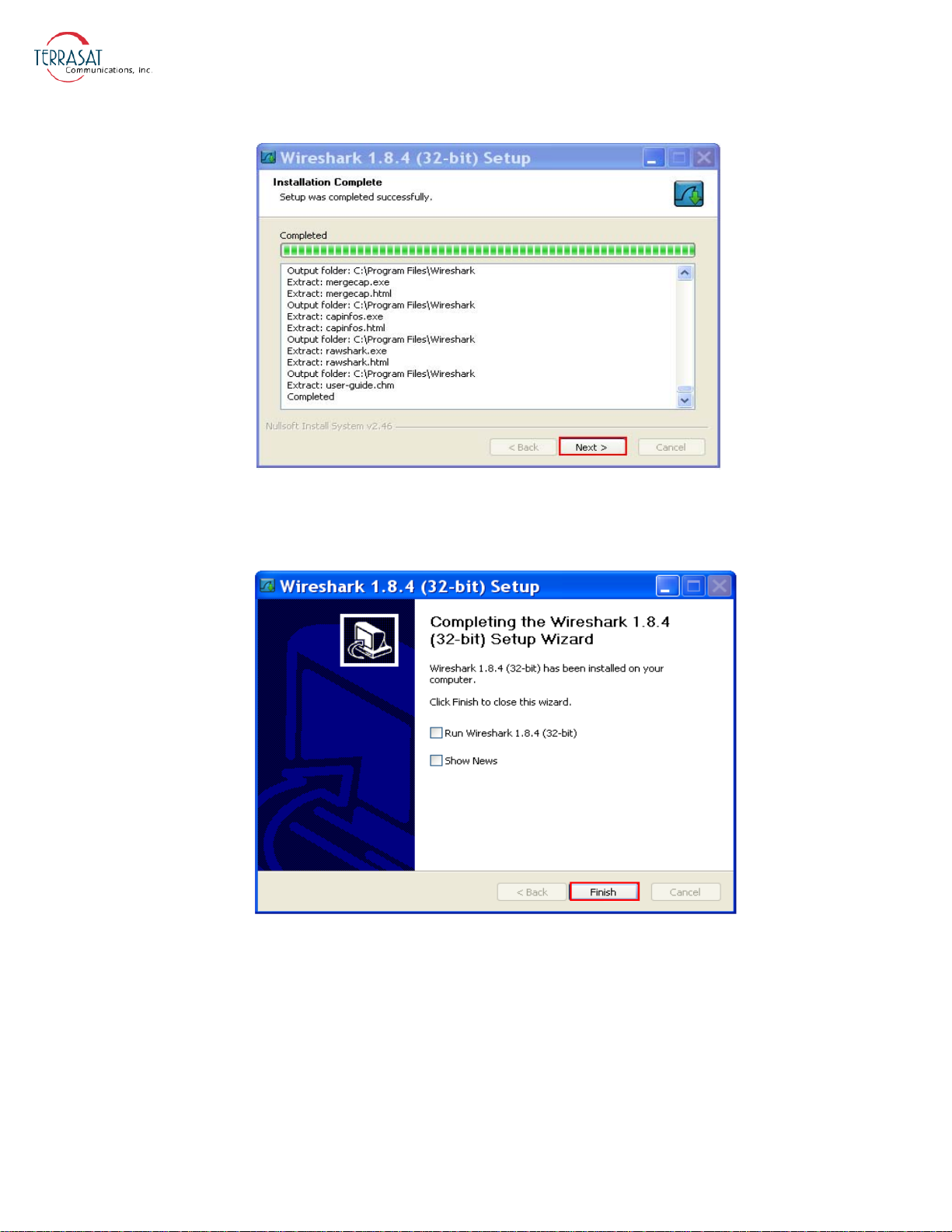
Figure 5.14
Setup Completion Notification
15. A window similar to the one shown in Figure 5.15 appears to notify you that
installation is complete. Click Finish.
Figure 5.15
Finishing Setup of Wireshark
To run Wireshark,
1. Attach an Ethernet cable between your computer and the J4 connector of the
IBUC.
2. Double-click the Wireshark icon on the desktop or choose Start → All Programs
→ Wireshark. A new window appears that contains the Wireshark interface.
5-16 | IBUC 2, IBUC 2e, IBUC 2G, IBUC R Operations Manual: Monitor and Control Features
Page 99
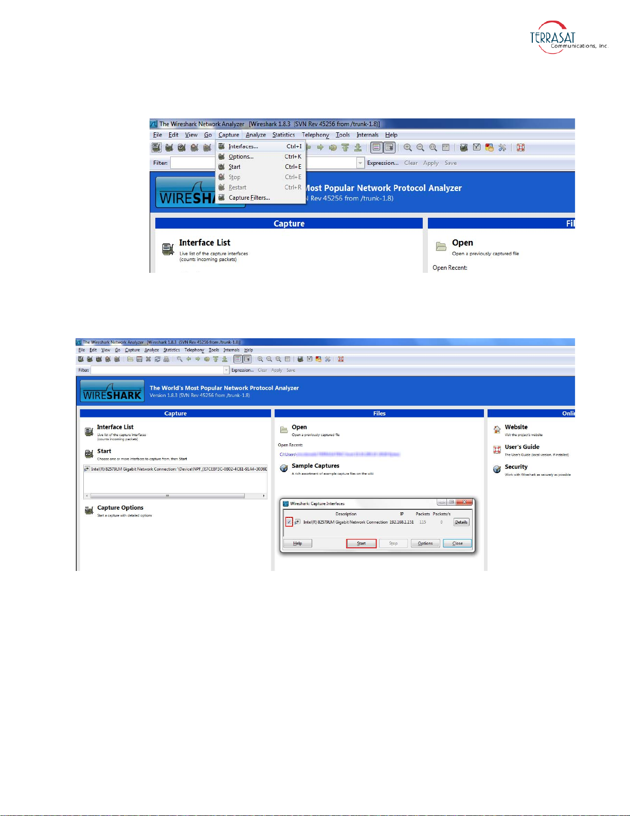
3. Choose Capture → Interfaces as shown in Figure 5.16. A list of interfaces appears.
Figure 5.17
Figure 5.16
Wireshark Menu
4. Select the interface for which you need to find the IP address by checking the box
next to its name, and then click
Selecting An Interface
Start.
5. Cycle power to the IBUC.
6. A results screen similar to the one shown in Figure 5.18 appears. Look for the text
“Gratuitous ARP for <your IP> Request”. In this example, the IP
address has been highlighted.
M&C Interfaces | 5-17
Page 100
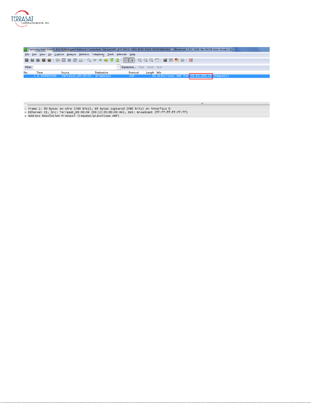
Figure 5.18
Returning IP Address Information
7. Record the IP address for future reference.
Telnet
Telnet is a simple, text-based program that enables you to connect to another computer
by using the Internet. You can connect to the IBUC by using a Telnet client from the
host PC. Telnet uses the ASCII command set listed in Appendix F, ASCII Command/
Response Structure. The default port for Telnet is 23. Characters are echoed back to
the user. The response format varies depending on the message setting type. If the
verbose setting is used, the response contains formatting characters which display
neatly to the user. If the terse setting is used, the response contains no formatting
characters and is terminated with LF and CR. If verbose mode is used, the response is
terminated with IBUC>.
To initiate a session,
1. Activate a command prompt window from the host computer.
2. Type Telnet 192.168.1.21 and a cursor should appear on the left of the
screen.
3. Type the password command CPE=1234.
You can now use ASCII commands to configure and monitor the IBUC. For more
information, see
Appendix F.
Web Server
You can access embedded Web pages that contain status and configuration
information.
Connect to the IBUC M&C and type the IP address of the IBUC through a Web
browser. A login page then appears. After login, you have a choice of eight Web pages
(nine pages if using redundant IBUCs) with monitoring, control, and alarm
information. Individual pages are displayed by clicking the tabs at the top of the Web
5-18 | IBUC 2, IBUC 2e, IBUC 2G, IBUC R Operations Manual: Monitor and Control Features
 Loading...