


T5C


1.1
Safety Tips
Safety is a prime consideration in the design of this
machine. Guards, shields and other safety features are
built in wherever possible. However, accident reports
show carelessness causes the majority of accidents. You
can avoid most accidents by observing the safety rules on
these pages. Study these rules carefully and enforce them
on the job:
Never allow minors to operate or be in the
vicinity of the machine while working.
Do not allow the T5C to be operated by anyone
who is intoxicated or on medication that would affect
their judgement or ability to operate the machine.
The machine is designed to be operated by
adults who are of average size and weight. Persons
who are extremely heavy, big or tall, or those who
are exceedingly short, light or weak can not run the
machine.
Before Operating the Terramite T5C
Read the Operator's Handbook. Never
allow anyone to operate the backhoe without
reading the Operator's Manual and Safety
Instructions. This should be followed by supervised
training.
Check Your Equipment. Always make a
complete inspection of the machine before
operating it that day. Check the hydraulic system
and the engine oil level. Then check the machine
for broken, missing or defective parts. Check the
tires for cuts, bulges, irregularities and abnormal
wear and proper inflation. Check the neutral
position of the foot pedal. A malfunctioning
machine invites accidents.
"Do Not Operate" Tag. When you service
the machine, put a "DO NOT OPERATE" Tag on
the instrument panel. This tag (Terramite Part
Number 1-400.82) is included with each machine.
Keep Your Machine Clean. Slippery
surfaces are hazardous. Remove oil, grease or mud
from the operating area of the tractor. Failure to
keep these areas clean could cause a serious
accident.
Wear What is Needed for Protection.
Protect yourself by wearing all the protective
clothing and personal safety devices issued to you
or required by job conditions. You may need a hard
hat, safety shoes, safety glasses, heavy gloves,
hearing protection, reflective clothing, wet weather
gear and a respirator. Never take chances by wearing
loose clothing, watches or rings.
Look For Hazards. Walk around a new work
area and check for any hidden hazards, such as holes
and abutments.
Read and Heed Safety Decals. Make sure
the safety and information decals can be easily read.
To clean decals, use soap and water only. Gasoline
or solvents will destroy the decals. If these decals
are missing or illegible, call our Parts/Service
Department for replacements.
Roll-Over Protective Structure. All
Terramite T5C tractor loader backhoes are equipped
with a Roll-Over Protective Structure. This is
designed to protect the operator in the event of a
roll-over. If this machine has been rolled over, the
R.O.P.S. must be replaced. It is designed to be used
only once.
Driving Pivot Pins. When driving pivot pins
in or out, use care to guard against injury from
particles that may chip off the pin or object used in
striking the pin. These pins can fly out at high speed
if they are not tapped lightly just before they come
out. Make sure there isn't anyone or anything in
the way, in case the pin flies out. Safety glasses
should be worn.
See Operator's Manual For More Safety Information
IMPORTANT! If this machine is used by the owner, an employee, or is
loaned or rented, make sure that the following instructions are complied
with:
1. The operator has read the Operation and the Safety Rules
sections of the Operator's Handbook.
2. He has been instructed on the safe and correct use of the
machine.
3. He has practiced operating the machine and the use of all
controls in a safe, clear area before he operates the machine on a
job site.
4. He has read all safety decals on the machine.
5. He has been informed to clear the area of other persons and
hidden hazards before starting the machine.
Before Your Start
READ OPERATOR'S HANDBOOK
Carefully read all WARNING! and DANGER! messages in handbook
and be sure you understand their meanings.
1.2

Table of Contents
Safety - Important ................................................ 1.1
Before Operating the Terramite T5C................... 1.2
Section Two: HYDRAULICS
Oil Change and Type Specifications .................... 2.1
Front with Loader Arm Assembly Raised ............. 2.2
Loader Valve Hoses and Fittings
Under Fuel Tank Hood Assembly ........................ 2.3
Transmission Assembly ......................................... 2.4
Rear Valve ...................................................... 2.5-2.7
Gear Pump Part #66045 ...................................... 2.8
Rod Assembly ....................................................... 2.9
Hydrastatic Transmission .................................... 2.10
Hydraulic Main Power Circuits(Gas Model) ...... 2.11
Hydraulic Main Power Circuit ........................... 2.12
Loader Circuit .................................................... 2.13
Woddlestick Hose Diagram Backhoe Circuit ..... 2.14
MAB/MAE Torquemotor Exploded................... 2.15
Power Steering Column Exploded ..................... 2.16
Schematic - Backhoe Control Valve .................. 2.17
Parts Ordering Information ................................ 2.18
V20 Seal Identification Chart
Loader Valve ...................................................... 2.19
4-Way, 3-Position Valve Section ......................... 2.20
Loader Check Plug / High Pressure Releif .......... 2.21
Section Three: COMPONENTS
Seat Assembly ...................................................... 3.1
Exploded View of Front End Loader .................... 3.2
Exploded View of Dash ........................................ 3.4
Under the Hood - Kohler Command Engine ....... 3.6
Drive Shaft Coupler ............................................. 3.7
View from Behind Center Steer ........................... 3.8
View from Behind Dash ..................................... 3.10
Front Wheel Hubs / Hub Assembly and Spindle 3.12
Front / Rear Tires and Rims ................................ 3.13
Parking Brake Assembly ..................................... 3.14
Retro Fit Parking Brake Spring Assembly ........... 3.16
Front of Rear Axle - Parking Brake Assembly .... 3.16
Exploded View of Dipstick ................................. 3.17
Backhoe Assembly ............................................. 3.18
Rear Axle Assembly ........................................... 3.20
Pin Schematic .................................................... 3.22
General Tightening Torque for Bolts, Nuts
and Taperlock Studs ........................................... 3.23
Decal Location Right Side ................................. 3.24
Decal Location - Dash ....................................... 3.25
Decal Location - Rear ........................................ 3.26
Couplings ........................................................... 3.27
Section Four: ELECTRICAL WIRING
Diagram Kohler Magnum 20 HP ......................... 4.1
Diagram Kohler Command 20/25 HP .................. 4.2
Harness/A-Kohler Command ............................... 4.3
Diagram Honda 20 HP ........................................ 4.4
(Pre - 1997 Model) .......................................... 4.5
Harness/A-Relay Harness ..................................... 4.6
Harness/Honda Engine ........................................ 4.7
Harness/Honda Voltage Regulator Harness/
A-Relay Harness ............................................... 4.8
Harness - Honda Dash ......................................... 4.9
Section Five: OPTIONS
Tires ..................................................................... 5.1
Work Lights and Canopy/Mounted Lights
Strobe Light ..................................................... 5.2
Clam Shell 4 in 1 Bucket ..................................... 5.3
Under Dash for Clam Shell 4 in 1 Bucket ........... 5.4
Drive Position
Dash for Clam Shell Buck ................................ 5.5
Street Pads/Flip Over Pads/Tooth Caps ................ 5.6
Quick Attach Backhoe Buckets (After 5-1-98) ... 5.7
Auger (Bradco./McMillen)................................... 5.8
Auger Connections .............................................. 5.9
Back-up Alarm and Connections....................... 5.10
Section Six: TRANSLATIONS
Translations ................................................ 6.1 to 6.6
Section SEVEN: INDEX & SAMPLE WARRANTY
Index .......................................................... 7.1 to 7.5
Sample Warranty .................................................. 7.6
RECORDS
Serial Number _________________________
Model# ______________________________
Engine Type: __________________________
Engine Serial Number: __________________
Accessories: ___________________________
____________________________________
____________________________________
____________________________________
1.3

1.4
Copyright © 2006 Terramite Corporation
2.1
WWW.TERRAMITE.COM/SAFETY
1.800.428.3772
Intl. 1 .304.776.4231
Charleston, WV/USA
PARTS MANUAL
Read Operators Manual For Safety
Hydraulics
Oil Change and Type Specifications
When your machine is new, the hydraulic system oil and filter must be changed within the first 50
hours of use and every 250 thereafter. Refill the hydraulic reservoir with engine oil type API SF.CD
15W40 when outside temperature is above 40 degrees F. Use engine oil type API SF.CD 10 weight
when outside temperature is below 40 degrees F. Replace filter with Terramite / 21002 filter. It is
important to follow these instructions to alleviate any cold weather engine starting problems and any
pressure or heat related component failures.
DO NOT USE REGULAR HYDRAULIC OIL!
MAJOR DAMAGE WILL RESULT!
This is the position machine must be in to check proper level in
hydraulic tank.
Required Pre-Fuel Filter Changes for Gasoline and Diesel Machines
ALL Terramite Backhoes and Street Sweepers require their pre-fuel filters to be changed at the first
20 hours and again at 40 hours. These pre-fuel filters should be changed every 20 to 50 hours
thereafter using a 10 micron filter.
The following Pre-fuel filters are designed for gasoline and diesel engines.
Terramite 15506
NOTE:NOTE:
NOTE:NOTE:
NOTE: Filling tank with loader or backhoe in any other position will result in overfilling and spillage of fluid
through the breather cap. Replace cap if oil should ever spill out of breather cap since it will clog off
the air supply that the systems needs to operate properly.
Copyright © 2006 Terramite Corporation
2.2
WWW.TERRAMITE.COM/SAFETY
Charleston, WV/USA
1.800.428.3772
Intl. 1 .304.776.4231
Read Operators Manual For Safety
PARTS MANUAL
Hydraulics
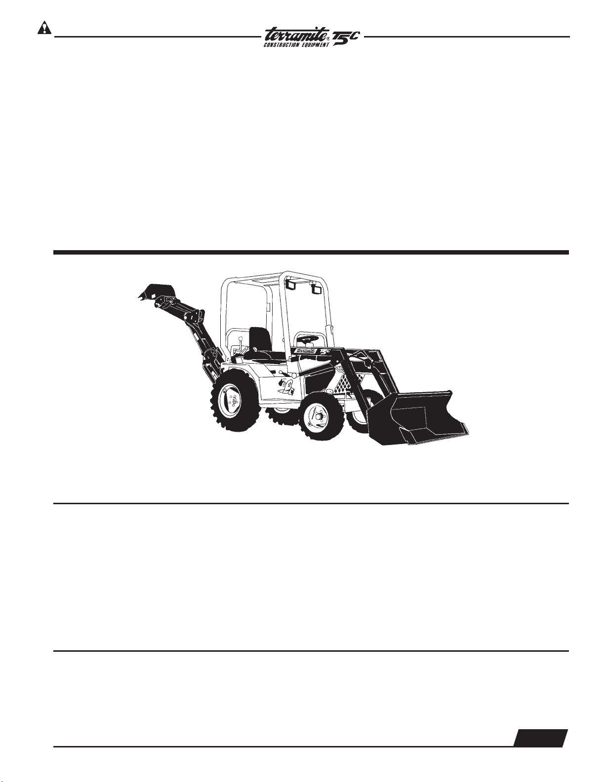
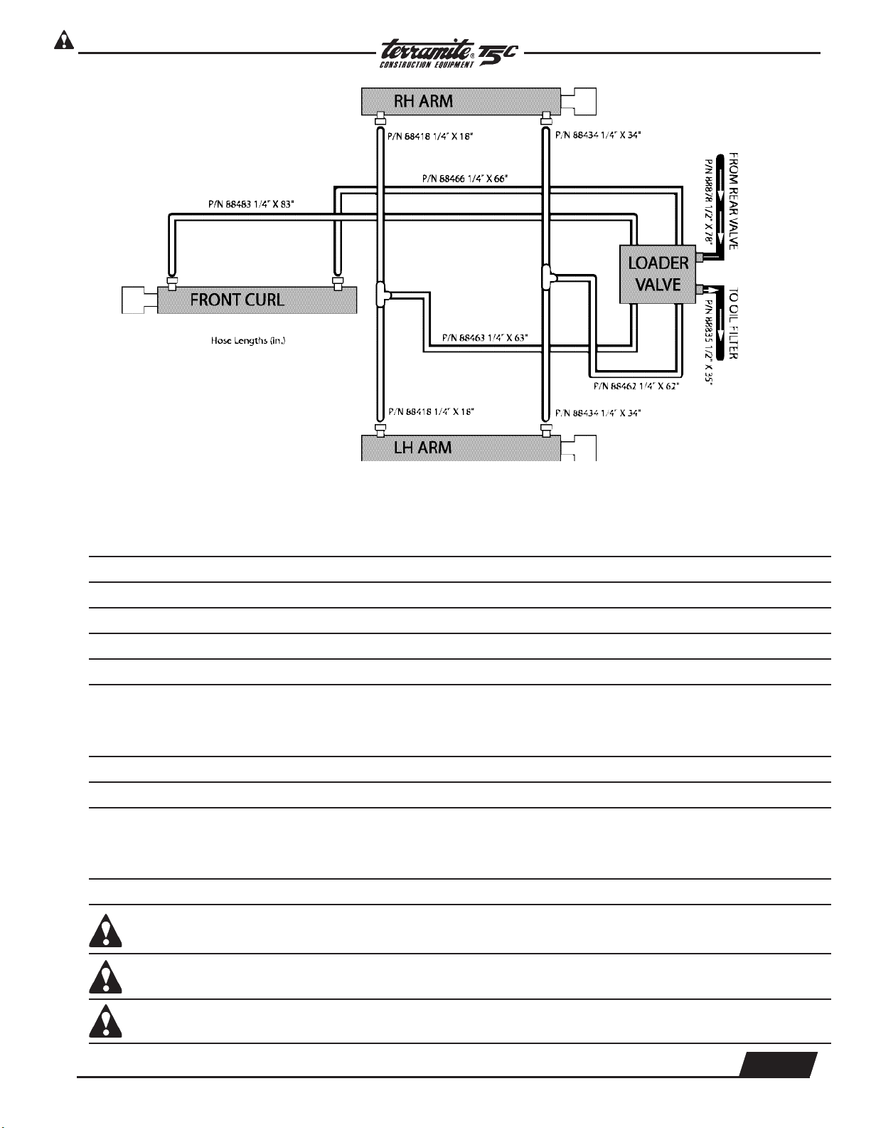
ITEM PART NUMBER DESCRIPTION QTY.
1 88418 Hose,
1
/4" x 18" (front hose set) 2
2 22244 Fitting,
1
/4" Tee (front hose set) 2
3 20174 Fitting,
1
/4" (front hose set) 26
4 88434 Hose,
1
/4" x 34" (front hose set) 2
5 22174 Fitting,
1
/4" x 90° (front hose set) 5
6 88462 Hose,
1
/4" x 62" (front hose set) 1
7 88463 Hose,
1
/4" x 63" (front hose set) 1
8 12033 Distributor Block 1
View from Front with Loader Arm Assembly Raised
2
3
1
8
4
5
6
4
7
1
Copyright © 2006 Terramite Corporation
2.3
WWW.TERRAMITE.COM/SAFETY
1.800.428.3772
Intl. 1 .304.776.4231
Charleston, WV/USA
PARTS MANUAL
Read Operators Manual For Safety
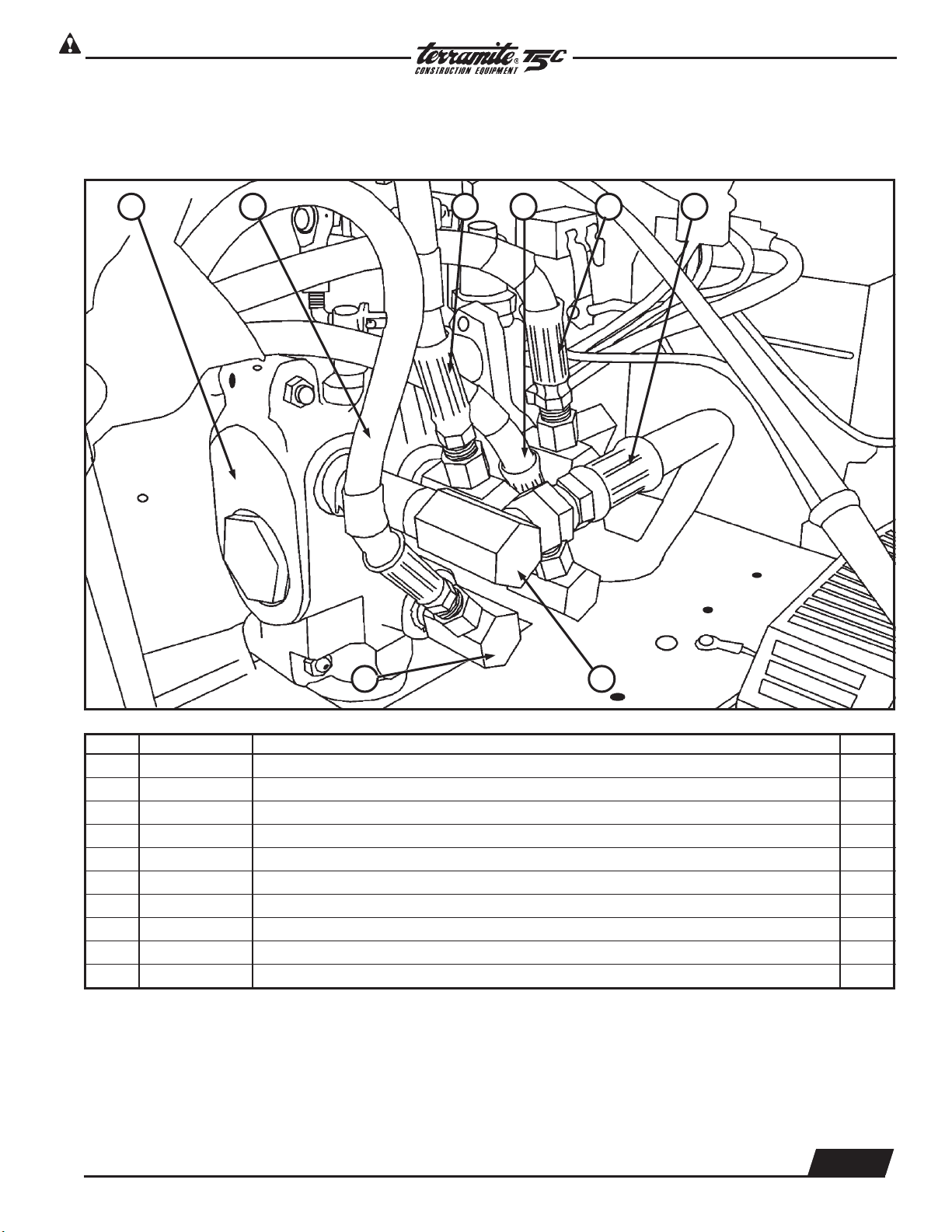
Hydraulics
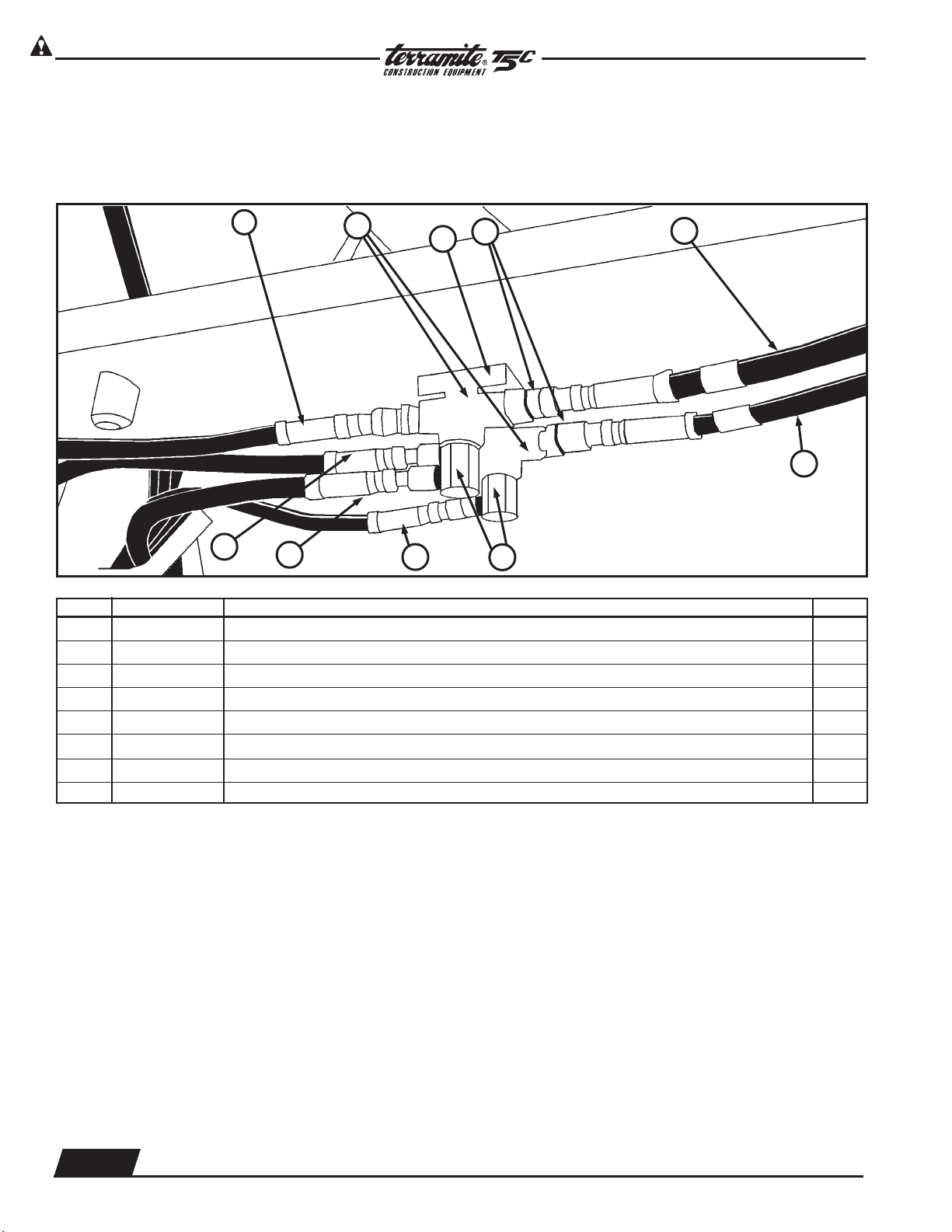
View of Loader Valve Hoses and Fittings from Right Side of Engine
Compartment Under Fuel Tank Hood Assembly
ITEM PART NUMBER DESCRIPTION QTY.
1 85015 Valve, Loader(No Fittings) 1
1 84070 Valve, Loader(With Fittings) 1
2 88483 Hose,
1
/4" x 83", Loader Valve 1
3 88466 Hose,
1
/4" x 66", Loader Valve 1
4 88463 Hose,
1
/4" x 63", Loader Valve 1
5 88462 Hose,
1
/4" x 62", Loader Valve 1
6 88835 Hose,
1
/2" x 35", Loader Valve 1
7 22278 Fitting,
1
/2" x 90°, Loader Valve 1
8 22784 Fitting,
1
/2" x
1
/4" x 90°, Loader Valve 4
13096 Front Valve Seal Kit 1
1 2 3 4 5 6
78
Copyright © 2006 Terramite Corporation
2.4
WWW.TERRAMITE.COM/SAFETY
Charleston, WV/USA
1.800.428.3772
Intl. 1 .304.776.4231
Read Operators Manual For Safety
PARTS MANUAL
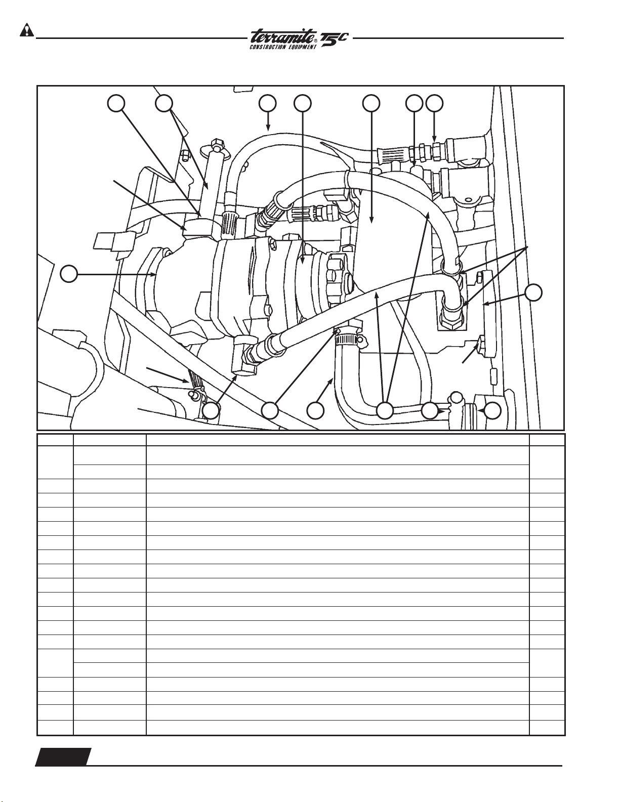
Hydraulics
ITEM PART NUMBER DESCRIPTION QTY.
1
64064 Hydrostatic Transmission Gas Only (Resale)
1
64012 Hydrostatic Transmission Diesel Only
2 11620 Pedal Shaft 1
3 61623 Pedal Shaft Bushing 1
4 88615 Hose,
3
/8” x 15”, Transmission 1
5 66045 Gear Pump 1
6 21002 Filter, Hydraulic 1
7 22003 Filter Base 1
8 21786 Fitting,
1
/2” x
3
/8”, Trans. 1
9 15900 Tank, Hydraulic, T5 1
10 64003 Torquemotor 1
11 22201 Filter, Strainer (Inside Tank) 1
12 22020 Clamp, Hose 2
13 88820 Hose,
1
/2” x 20”, Trans. 2
14
81012 Hose,
3
/4" x 12", Trans. prior to 11-92
1
81010 Hose,
3
/4" x 12", Trans. after 11-92
15 81612 Fitting, 1
1
/16” x
3
/4”, Trans. 1
16 27128 Fitting, #12 x
1
/2" x 90°, Trans. 2
25286 Fitting On Bottom of Transmission
22118 Fitting For Charge Plate Adapter 3/8 90%
View from Top - Transmission Assembly
3 4 5 6 7 8
111213141516
2
1
Block #13054
PN#80037
Bolt #22034
Nut #28500
10
Fitting
#20007
Roll Pin #17005
Copyright © 2006 Terramite Corporation
2.5
WWW.TERRAMITE.COM/SAFETY
1.800.428.3772
Intl. 1 .304.776.4231
Charleston, WV/USA
PARTS MANUAL
Read Operators Manual For Safety
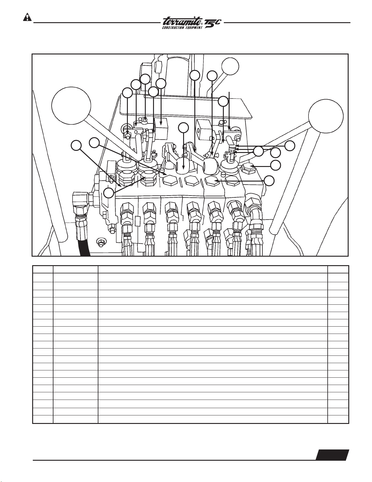
Hydraulics
ITEM PART NUMBER DESCRIPTION QTY.
1 25500 Nut,
5
/16" NF Jam 2
2 13444 Wobblestick Pivot Block, Universal 1
3 16410 Eye Bolt 2
4 13965 Linkage 3
5 13443 Connecting Link 2
6 13411 Valve Link 3
7 13410 Aluminum Valve Handle Bracket 2
8 13418 Pin, Valve Hose Link Pivot 8
9 21429 90
o
Grease Fitting 1
10 23008 Nut on back of Wobblestick 1
11 13443 Lock Nut 1
12 13431 Outrigger Handles 2
13 13429 Main Relief Rear Valve 1
14 13423 Valve Boot Spool Protector 4
15 13401 Load Check Plug Assembly 9
16 13456 Port Relief 2600# 1
17 13454 Port Relief 2000# 2
18 13444 Uni Blocks
85041 Orings 6
13499 Pressure Shims
View from Operator Position of Rear Valve
1
2
3
18
8
12
6
5
14
16
7
Bolt 10
17
7
4
15
3
13
Copyright © 2006 Terramite Corporation
2.6
WWW.TERRAMITE.COM/SAFETY
Charleston, WV/USA
1.800.428.3772
Intl. 1 .304.776.4231
Read Operators Manual For Safety
PARTS MANUAL
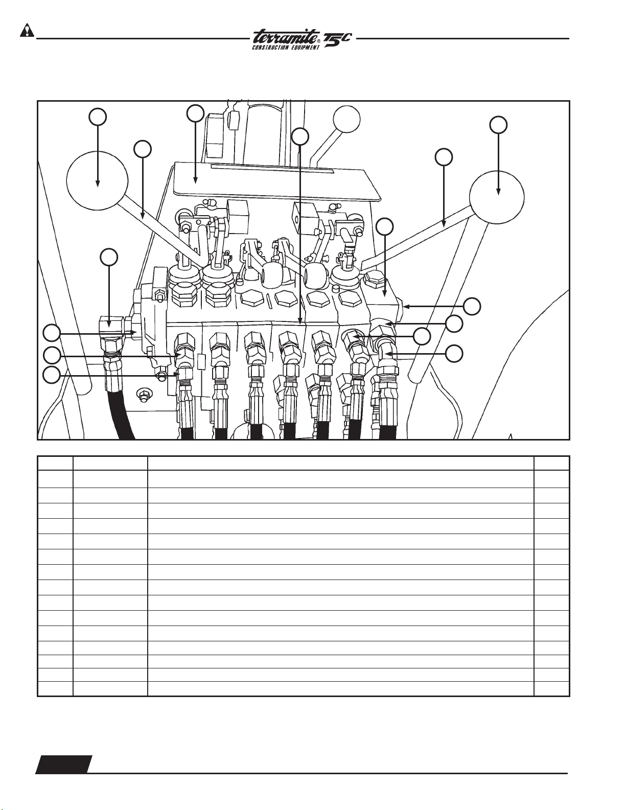
Hydraulics
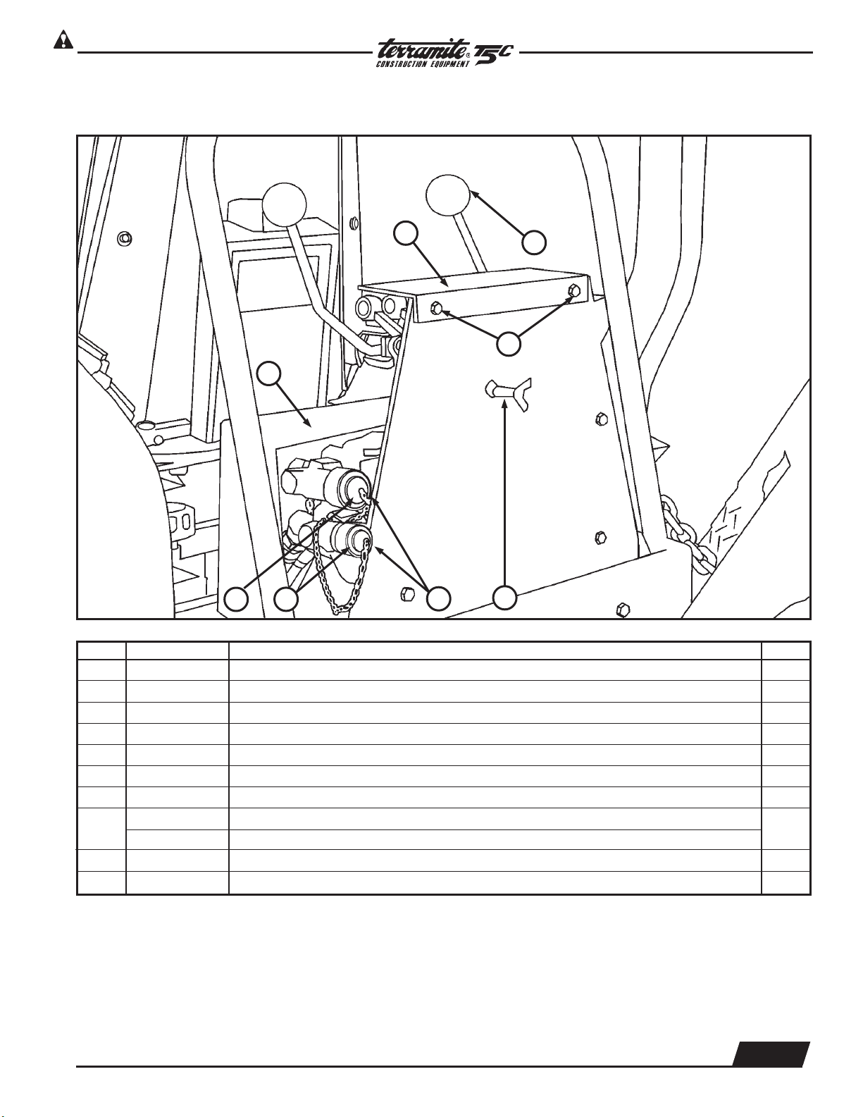
ITEM PART NUMBER DESCRIPTION QTY.
1 13942 Knob 2
2 13073 Handle, Wobblestick, Left Rear 1
3 14050 Decal, Wobblestick & Operator Hazard 1
4 13123 Handle, Wobblestick, Right Rear 1
5 13400 Rear Valve Assembly 1
6 20065 Fitting, #12 x 8" adaptor 2
7 21788 Fitting, #8 x
1
/2" x 45° 2
8 25286 Fitting, #8 x 6" adaptor 12
9 21764 Fitting,
3
/4" x
1
/4" x 45° 9
10 21765 Fitting, Restrictor 3
11 25108 Fitting, #10 x
1
/2" x 90° 1
13444 Block
12 84029 Power Beyond - Sleeve Kit
13 85156 End Cap
14 26002 Restrictor Sets Screws
View from Operator Position of Rear Valve
1
3
1
18
11
5
12
10
4
2
9
6
8
13
End Cap
7
Copyright © 2006 Terramite Corporation
2.7
WWW.TERRAMITE.COM/SAFETY
1.800.428.3772
Intl. 1 .304.776.4231
Charleston, WV/USA
PARTS MANUAL
Read Operators Manual For Safety
Hydraulics
ITEM PART NUMBER DESCRIPTION QTY.
1 25054 Q.A. Plug 1
2 27010 Threaded Q.A. Plug 1
3 28890 Auxiliary P.T.O. Kit 1
21188 Fittings,
1
/2” x 90° 2
4 26485 P.T.O. Depress Lever 1
5 14052 Decal Plate For Handle Operations 1
6 13942 Wobblestick Knob 2
7
14005 Maintenance Decal (Gas Only) Located Under Dash Not Shown
1
14510 Maintenance Decal (Diesel Only) Located Under Dash Not Shown
8 Bolts 2
9 15017 Hose Cover
3
View from Right Rear
NOT
SHOWN
2
1
6
4
5
8
9
Copyright © 2006 Terramite Corporation
2.8
WWW.TERRAMITE.COM/SAFETY
Charleston, WV/USA
1.800.428.3772
Intl. 1 .304.776.4231
Read Operators Manual For Safety
PARTS MANUAL
Hydraulics
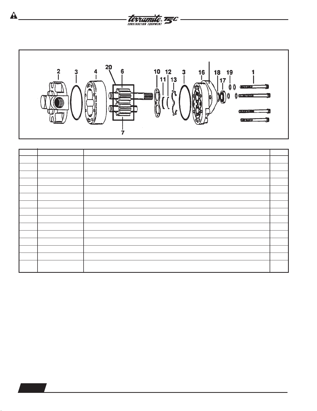
Serial Code and Assembly Number
Gear Pump Part # 66045
ITEM PART NUMBER DESCRIPTION QTY.
1 NSS* Cap Screws 8
2 64501 Backplate Assembly 1
3 60464 O-Ring
1
/16" x 3" 1
4 64504 Body 1
6 64505 Drive Gear Assembly 1
7 64506 Idler Gear Assembly 1
10 NSS* Wear Plate 1
11 NSS* Bearing Seal 1
12 NSS* Molded O-Ring 1
13 NSS* Back Up Gasket 1
16 64513 Front Plate 1
17 64514 Seal, Gear Pump, Shaft 1
19 65131 Washer, Gear Pump 4
SP 65101 Seal Repair Kit 1
20 66010 2-Keys 2
NSS* Not Sold Separately
Copyright © 2006 Terramite Corporation
2.9
WWW.TERRAMITE.COM/SAFETY
1.800.428.3772
Intl. 1 .304.776.4231
Charleston, WV/USA
PARTS MANUAL
Read Operators Manual For Safety
Hydraulics
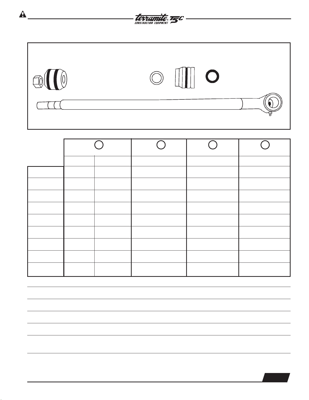
ROD BEARING BLOCK PISTON SEAL KIT
RO D PART PART PART PART
DIAMETER NUMBER NUMBER NUMBER NUMBER
Arm 1" 22501 22103 21111 21151
Power Steering 1" 25803 22103 21111 21151
Swing 1" 25201 22103 21111 21151
Front Curl 1
1
/8" 23101 22203 21111 21125
Rear Curl* 1
1
/8" 20301 22203 21111 21125
Outrigger 1
1
/8" 21601 22203 21111 21125
Boom Lift 1
1
/4" 21201 82058 23110 21525
Boom Crowd 1
1
/4" 21201 82058 23110 21525
2 inch 1
1
/4" 81048 82104 21111 82051
*Standard
**On machines manufactured before 6-96 part number is 25801 (Previous Part Number 1-58.1).
NOT SHOWN: Rear Curl Rod 1
1
/4" Part Number: 81048
NOTE: All rod assemblies use the same locknut Part Number 23420 (Previous Part Number 1N12FL).
NOTE: Units dated before 4-91 use aluminum pistons in 2" ID Cylinder Barrels only.
Use Seal Kit 2-15.1 (New #82049 for 1" kit-Prior to 4/94 Aluminum)
and 2-15.1125 (New #82050 for 1
1
/8" kit-Prior to 4/94 Aluminum).
1 2 3 4
SPECIAL TOOL 21176 Spanner wrench for cylinder repair
Rod Assembly
Copyright © 2006 Terramite Corporation
2.10
WWW.TERRAMITE.COM/SAFETY
Charleston, WV/USA
1.800.428.3772
Intl. 1 .304.776.4231
Read Operators Manual For Safety
PARTS MANUAL
Hydraulics
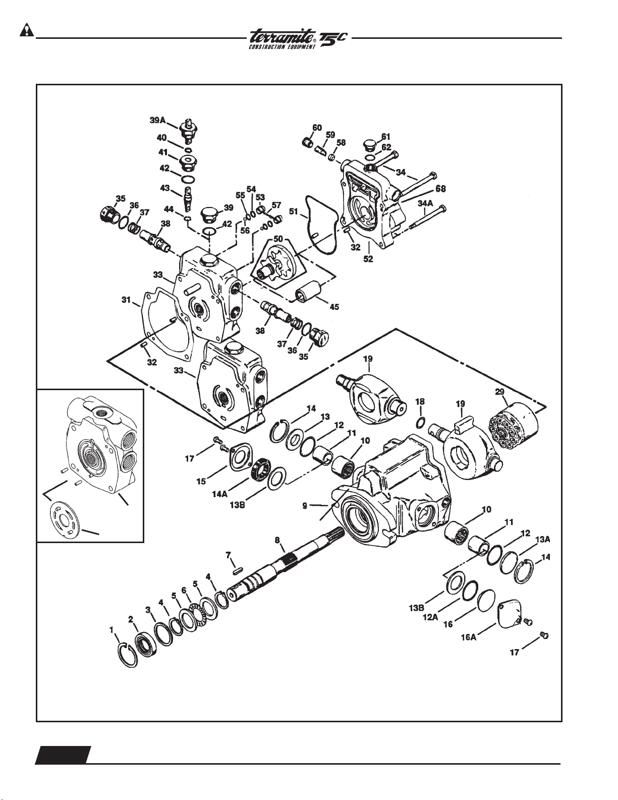
Hydrastatic Transmission
Serial Code and Assembly Number
Location
*
PLEASE PROVIDE SERIAL NUMBER OF MACHINE WHEN ORDERING ANY COMPONENT PARTS.
CESSNA
B
EATON
EATON
33A
67
EATON
CESSNA

Copyright © 2006 Terramite Corporation
2.11
WWW.TERRAMITE.COM/SAFETY
1.800.428.3772
Intl. 1 .304.776.4231
Charleston, WV/USA
PARTS MANUAL
Read Operators Manual For Safety
Hydraulics
ITEM PART NUMBER DESCRIPTION QTY.
1 60401 Retaining Ring 1
2 60402 Shaft Seal 1
3 60403 Washer 1
4 60404 Retaining Ring 2
5 60405 Bearing Race 2
6 60406 Bearing, Thrust 1
7 60471 Key 1
8 60407 Drive Shaft 1
9 60409 Housing Assembly 1
10 60410 Bearing 2
11 60411 Inner Race 2
12 60412 O-Ring,
3
/32" x
15
/16", Outer Pintle 2
13 60465 Sleeve Cover 1
13A 60415 Trunnion Cover 1
13B 60561 Washer 1
14 60414 Retaining Ring 2
14A 60562 Seal, Pintle 1
15 60418 Seal Cover 1
17 60564 Screws, Trunnion Cover 2
18 60516 O-Ring, Outer Pintle 1
19 60517 Camplate, For Eaton Trans. 1
19 60417 Camplate, For Cessna Trans. 1
29 60422 Rotating Kit Assembly 1
31 60429 Housing, Gasket 1
33 60533 Backplate Assy., Eaton, with Power Steering 1
33A 60535 Backplate Assy., w/valve plate, Eaton 1
33B 60432 Backplate Assy., Cessna, without Power Steering 1
35 60436 Plug Assembly 2
36 60435 O-Ring 3
3
/32" x
7
/8" ID, Back Plate 1
37 60434 Spring, Transmission, Relief Valve 2
38 60467 Relief Valve Assembly 2
39 60433 Plug Assembly 1
40 60440 Retaining Ring 1
41 60441 Separator Plug 1
42 60442 O-Ring, 3
3
/32" x
7
/8" 1
43 60454 Spreader 1
44 60437 O-Ring,
1
/16" x
3
/8" 1
45 60443 Coupler 1
50 64050 Gerotor and Coupler 1
51 60449 O-Ring, Molded 1
60453 Adapter Assembly without Power Steering
52 60553 Adapter Assembly with Power Steering 1
64058 Adapter Assembly with Power Steering - Diesel
53 60450 Check Valve Assembly 2
54 60452 Back Up Washer 2
55 60455 O-Ring,
1
/16" x
7
/16" 2
56 60456 Steel Ball 2
57 60457 Pin 2
58 60461 Poppet Filter Relief 1
59 60463 Spring 1
60 60560 Spring Retainer 1
61 60469 Plug Assembly 1
62 60466 O-Ring, 3
3
/32" x
41
/64"1
64 60464 O-Ring,
1
/16" x 3
1
/4" 1
65 60465 Cover Plate 1
66 60459 Cap Screw 2
67 60534 Plate, Valve 1
*S 64100 Seal Repair Kit, Cessna 1
*S 64101 Seal Repair Kit Eaton 1
*S 60043 Rotating Rebuild Kit, Cessna 1
*S 60564 Screws, Trunnion Cover 2
68 60464 O-Ring in Back 1
Copyright © 2006 Terramite Corporation
2.12
WWW.TERRAMITE.COM/SAFETY
Charleston, WV/USA
1.800.428.3772
Intl. 1 .304.776.4231
Read Operators Manual For Safety
PARTS MANUAL
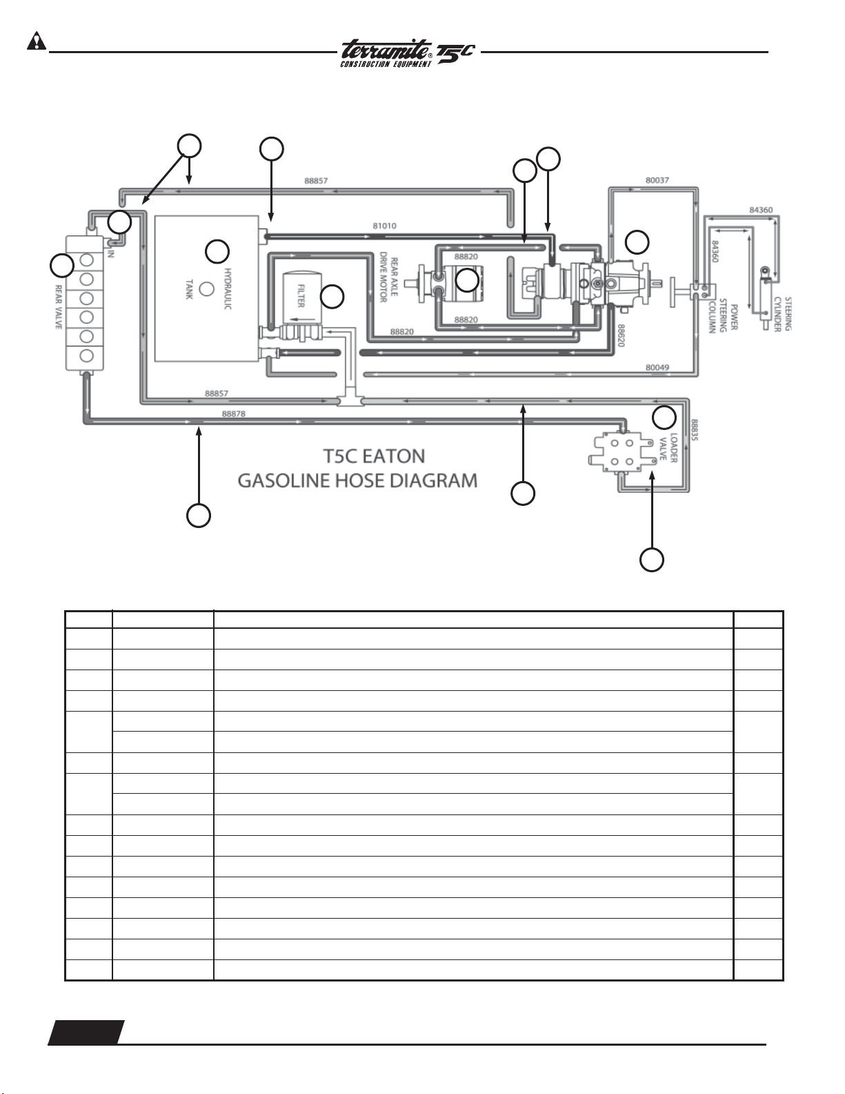
Hydraulics
ITEM PART NUMBER PREVIOUS PART NUMBER DESCRIPTION QTY.
1 13429 Main Relief Rear Valve 1
2 88857 Hose
1
/2" x 57" (back valve section) 2
3 22201 Filter, Strainer (Inside Tank) 1
4 64003 Drive Motor 1
5
81012 Hose,
3
/4" x 12"(back valve section) Prior to 11-92
1
81010 Hose,
3
/4" x 12"(back valve section) After 11-92
6 88820 Hose,
1
/2" x 20"(back valve section) 3
7
66005 Transmission Gasoline Type
1
66006 Transmission Diesel Equipped
8 13900 Valve Loader 1
9 13943 Loader Circuit Relief Valve 1
10 88836 Hose,
1
/2" x 36"(back valve section) 1
11 88878 Hose,
1
/2" x 78"(back valve section) 1
12 88620 Hose,
3
/8" x 20"(back valve section) 1
13 21002 Filter, Hydraulic 1
14 22204 Cap, Hyd. Breather Filter w/Dipstick 1
15 13400 Rear Valve Assembly 1
Continued On Next Page
Hydraulic Main Power Circuit (shown is for gas model)
9
8
13
4
7
14
15
1
2
10
11
3
6
5
Copyright © 2006 Terramite Corporation
2.13
WWW.TERRAMITE.COM/SAFETY
1.800.428.3772
Intl. 1 .304.776.4231
Charleston, WV/USA
PARTS MANUAL
Read Operators Manual For Safety
Hydraulics
Hydraulic Main Power Circuit (Continued)
HYDRAULIC FILTER TYPES:
PARKER 921999
NAPA 1551-1259
WIX 51551
FRAM P-1653
AC PF16
BALDWIN BT-839-10
HOSE TYPES:
3
/8" 2 WIRE BRAID MP6-6 & MB6-6F
1
/2" 2 WIRE BRAID NPT
3
/4" SUMP LINE HOSE
OIL:
ABOVE 40°F - API 15W-40 SF/CC/CD
BELOW 40°F - API 10w SF/CC/CD
WARNING: USE ONLY 2 WIRE BRAID HOSES AS SPECIFIED ABOVE. SYNTHETIC OR OTHER TYPES OF
HOSES MAY FAIL CAUSING SERIOUS INJURY OR DEATH.
WARNING: DO NOT USE ORDINARY HYDRAULIC OIL OR MAJOR DAMAGE TO TRANSMISSION AND
MOTOR WILL RESULT.
NOTE: For Diesel, switch hoses marked A and B
Loader Circuit
Copyright © 2006 Terramite Corporation
2.14
WWW.TERRAMITE.COM/SAFETY
Charleston, WV/USA
1.800.428.3772
Intl. 1 .304.776.4231
Read Operators Manual For Safety
PARTS MANUAL
Hydraulics
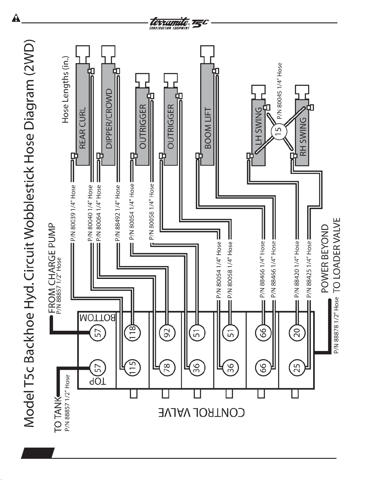
T5C Wobblestick Hose Diagram Backhoe Circuit
Copyright © 2006 Terramite Corporation
2.15
WWW.TERRAMITE.COM/SAFETY
1.800.428.3772
Intl. 1 .304.776.4231
Charleston, WV/USA
PARTS MANUAL
Read Operators Manual For Safety
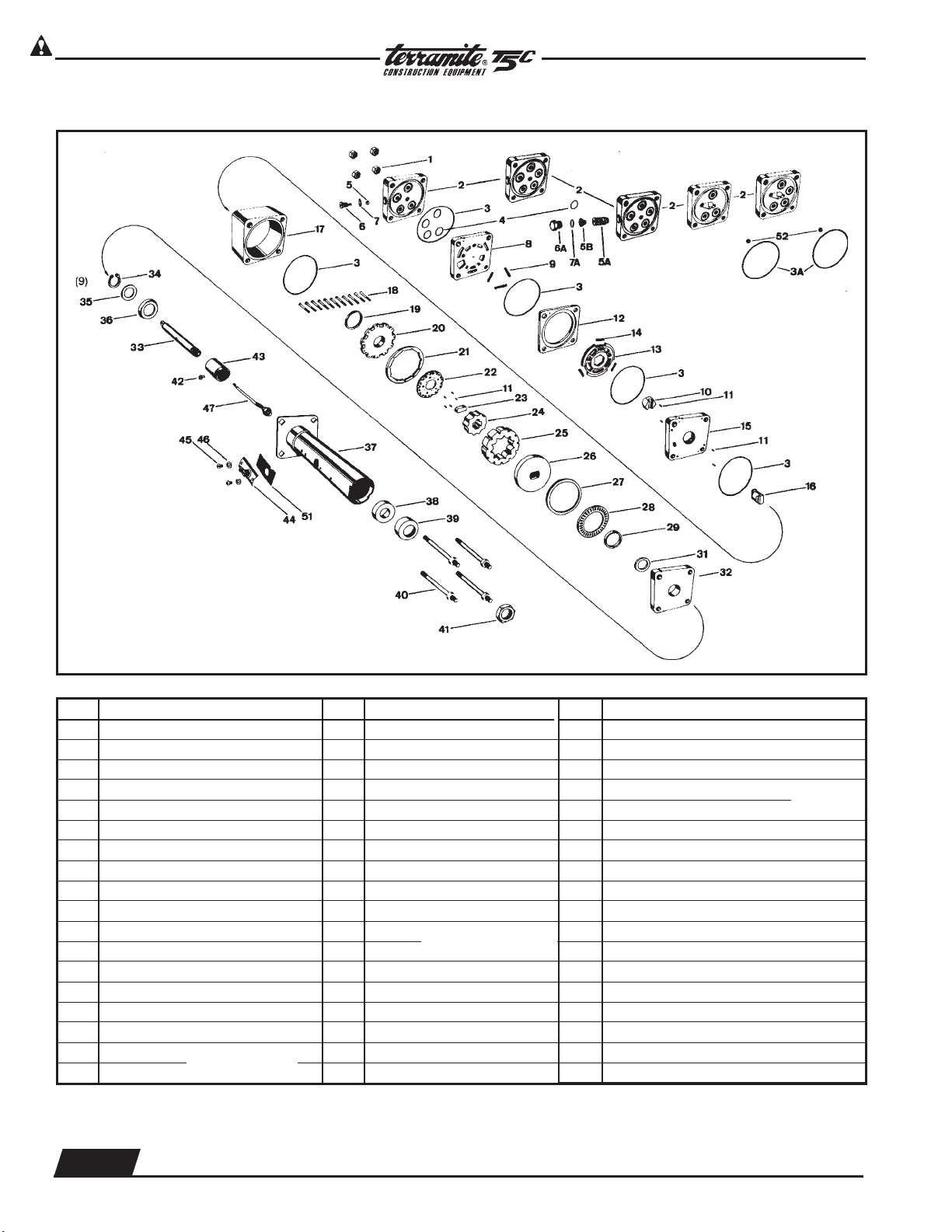
Hydraulics
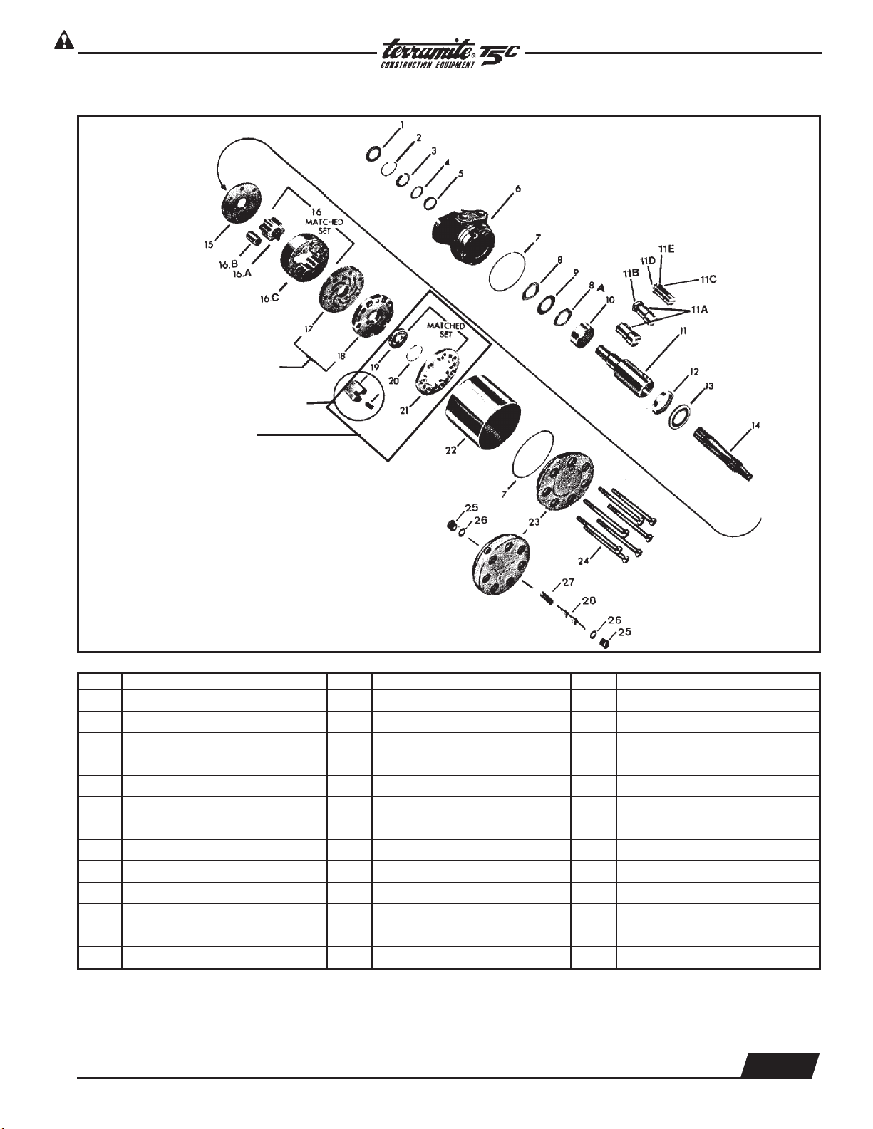
MAB/MAE Torquemotor Exploded Assembly View
ITEM DESCRIPTION ITEM DESCRIPTION ITEM DESCRIPTION
1 Seal 11B Nut 17 Manifold Plate
2 Retaining Ring 11C Washer 18 Manifold
3 Back-Up Washer 11D Bolt 19 Commutator
4 Washer 11E Lock Washer 20 Seal Ring
5 Seal 12 Bearing 21 Commutator Ring
6 Housing 13 Thrust Bearing 22 Sleeve
7 Seal Ring (2) 14 Drive Link 23 End Cover Assembly
8 Thrust Washer 15 Wear Plate 24 Special Bolt (7)
8A Thrust Washer 16 Rotor Set 25 Plug
9 Thrust Bearing 16A Rotor 26 O-Ring
10 Bearing 16B Vane (7) 27 Sping
11 Coupling Shaft 16C Stator 28 Valve (Shuttle)
11A Key
Commentator and Ring
PN# 62008
Copyright © 2006 Terramite Corporation
2.16
WWW.TERRAMITE.COM/SAFETY
Charleston, WV/USA
1.800.428.3772
Intl. 1 .304.776.4231
Read Operators Manual For Safety
PARTS MANUAL
Hydraulics
ITEM DESCRIPTION
1 Nut 5/16 UNF 24 (4)
2 Port Cover
3 Seal Ring (5)
3A Seal Ring (White)
4 O'Ring (3), (4) or (5)
5 Ball-
7
/32 inch (6mm) dia.
5A Relief Valve Cartridge
5B Coil Spring
6 Plug
6A Hex Plug
7 O'Ring, Plug & O'Ring Assy.
7A O'Ring
8 Port Manifold
9 Spring,
3
/4 inch (19mm) (3)
10 Hex Drive Assy.
11 Alignment Pin (Needle Brg.) (9)
12 Valve Ring
13 Valve Plate
14 Spring,
1
/2 Inch (13mm) (3)
15 Isolation Manifold
16 Drive Link
17 Metering Ring
18 Screw, Hex Socket Hd (11)
19 Seal, Commutator
20 Commutator Cover
21 Commutator Ring
22 Commutator
23 Spacer-Drive Link
24 Rotor
25 Stator
26 Drive Plate
27 Spacer-Trust Bearing
28 Thrust Bearing
29 Face Seal
31 Seal Spacer
32 Upper Cover Plate
Power Steering Column Exploded Assembly View
ITEM DESCRIPTION
33 Input Shaft/Wheel Tube
34 Retaining Ring
35 Washer-Retaining Plate
36 Retaining Plate
37 Upper Cover & Jacket Assy.
38A
7
/8 Bushing
38B
3
/4Bushing
39 Seal
40 Special Bolt,
5
/16 24UNF-2A
41 Nut
42 Screw
43 Contact Ring Assy.
44 Contact Brush Assy.
45 Screw & Lock Washer
46 Washer [for 1
1
/2 inch (38 mm) Jacket]
47 Horn Wire Cable Assy.
51 Spacer [for 1
1
/2 inch (38 mm) Jacket]
52 Ball
9
/32 inch (22mm)
}
Matched Set
}
Matched Set
}
Matched
Set
Items #44, 45, 46, 51 are not part of HGF service assembly unit. They must be
purchased as separate items of order.
ITEM DESCRIPTION
Copyright © 2006 Terramite Corporation
2.17
WWW.TERRAMITE.COM/SAFETY
1.800.428.3772
Intl. 1 .304.776.4231
Charleston, WV/USA
PARTS MANUAL
Read Operators Manual For Safety
Hydraulics
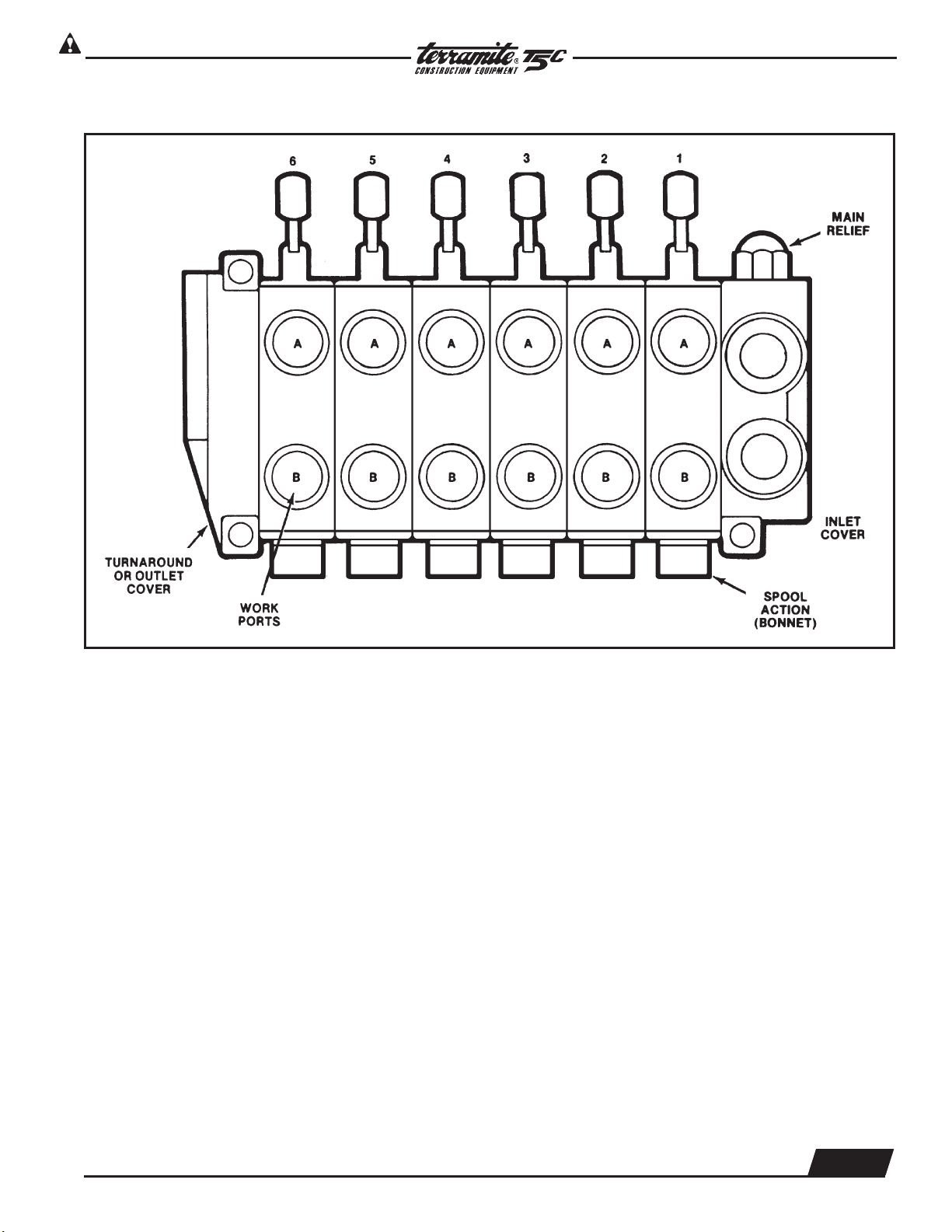
Schematic-View of Backhoe Control Valve Assembly
1. Before disassembly, it is suggested that each valve section be marked numerically to avoid incorrect
reassembly.
2. Remove three assembly stud nuts from the left end section using a
9
/
16
" thin wall socket.
3. Remove valve sections by sliding from assembly studs.
Copyright © 2006 Terramite Corporation
2.18
WWW.TERRAMITE.COM/SAFETY
Charleston, WV/USA
1.800.428.3772
Intl. 1 .304.776.4231
Read Operators Manual For Safety
PARTS MANUAL
Hydraulics
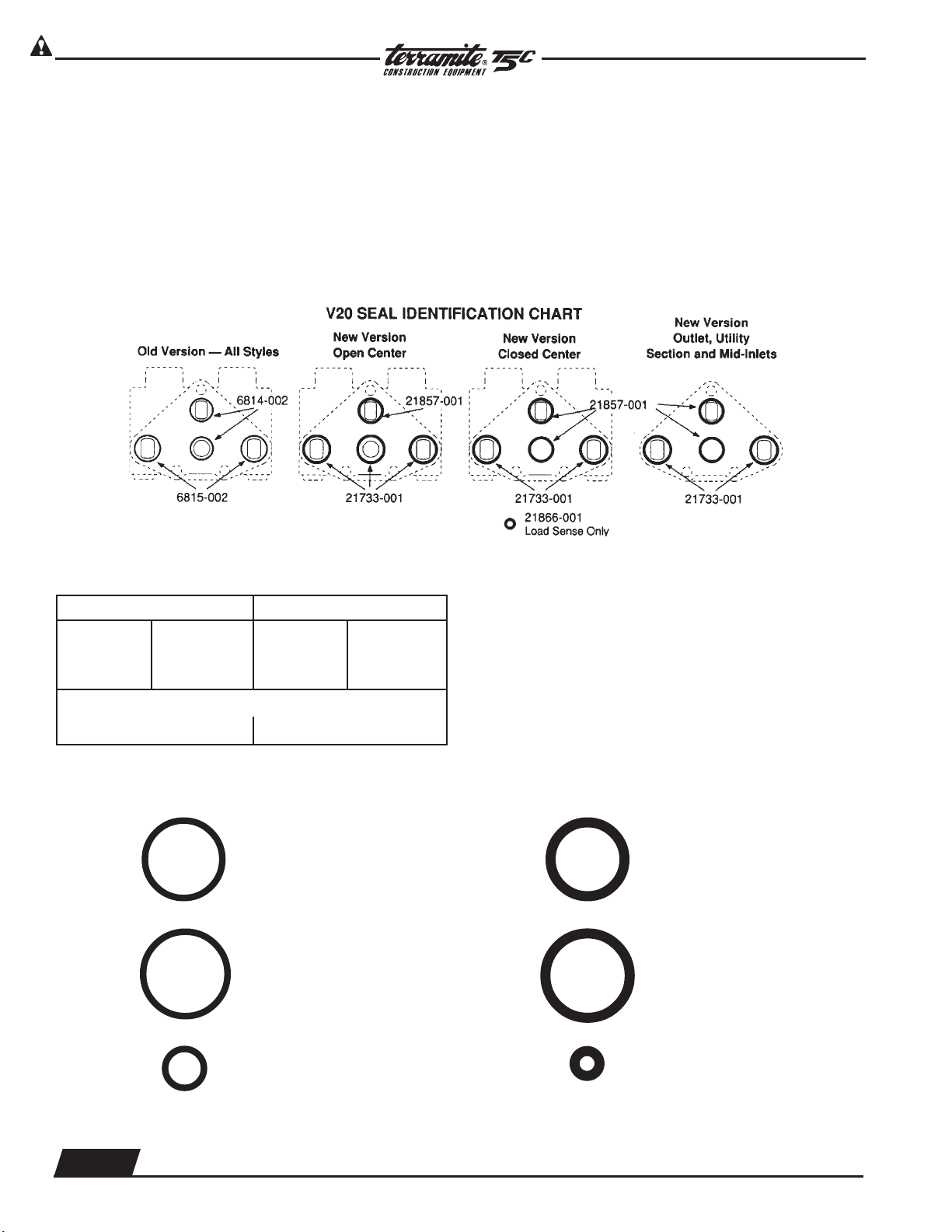
Parts Ordering Information
As of April 1, 1991, the section seals for the
V20 changed. The new versions have larger cross
section (old was .070, new is .103) and different con-
figurations for open center and closed center sec-
tions. The old design utilized the same seals for all
versions (two .801 I.D. and two .926 I.D.). The new
design uses one configuration for open center (three
.924 I.D. and one .799 I.D.) and another configuration
for closed center, load sensing and all outlet covers
(two .924 I.D. and two .799 I.D., with one .237 I.D. for
load sensing).
The following charts is provided to aid in se-
lection of the proper seals. It is important to note that
the seal kits include all O-rings (new and Old), there-
fore there will be some left unused.
The following section seals are included in the Kits:
Standard Kits Viton Kits
Old New Old New
(2)6814-002 (2)21867-001 (2)7450-001 (2)9003-117
(2)6815-002 (3)21733-001 (2)7451-001 (3)9002-119
Load sensing kits (additional seals)
(1)8316-001 (1)21866-001 (1)9002-011 (1)9002-108
Seal kit changes.
K-6121 Section Seal Kit, One Section
K-6027 Complete Seal Kit, 3 or 4 Way Section
K-6028 Complete Seal Kit, 4 Way Float Section
K-6209 Complete Seal Kit, Series 3 or 4 Way Section
K-6210 Complete Seal Kit, Series 4 Way Float Section
K-6154 Complete Seal Kit, Load Sensing 4 Way Float
K-6155 Complete Seal Kit, Load Sensing 3 or 4 Way Section
K-6156 Section Seal Kit, Load Sensing-One Section
K-6160 Viton Section Seal Kit, One Section
*Complete Seal Kits include spool seals and O-rings for check plugs.
OLD NEW
6814-002 ....... STD
7450-001 ....... VITON
6815-002 ....... STD
7451-001 ....... VITON
8316-001 ....... STD
9002-011 ....... VITON
21867-001 ..... STD
9003-117 ....... VITON
21733-001 ..... STD
9002-119 ....... VITON
21866-001 ..... STD
9002-108 ....... VITON
THESE SEALS ARE NOT INTERCHANGEABLE. OLD AND NEW STYLE SECTIONS MAY BE USED IN THE SAME ASSEMBLY
PROVIDED THE CORRECT SEALS ARE USED FOR EACH SECTION.
Seal Kit PN#85057 Prior to 1991
Seal Kit PN#85058 After 1991

Copyright © 2006 Terramite Corporation
2.19
WWW.TERRAMITE.COM/SAFETY
1.800.428.3772
Intl. 1 .304.776.4231
Charleston, WV/USA
PARTS MANUAL
Read Operators Manual For Safety
Hydraulics
Loader Valve
Detent Assembly
Power
Beyond
Relief
Valve
1. Raise and Lower Control Section
2. Curl and Dump Section
Copyright © 2006 Terramite Corporation
2.20
WWW.TERRAMITE.COM/SAFETY
Charleston, WV/USA
1.800.428.3772
Intl. 1 .304.776.4231
Read Operators Manual For Safety
PARTS MANUAL
Hydraulics
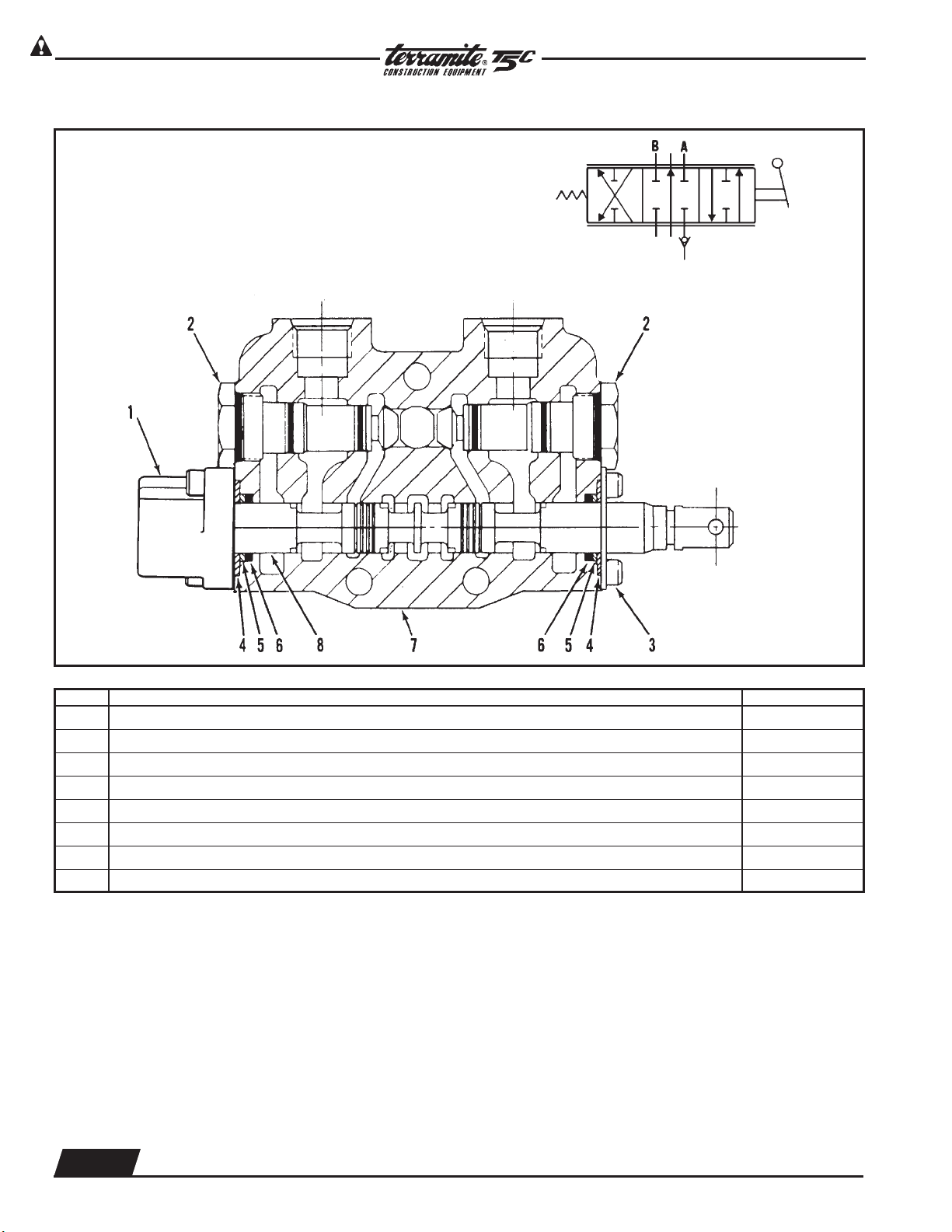
4-Way, 3-Position Valve Section
Notes:
1. Seal and washer not sold separately. Order Seal Kit.
2. These are matched parts and are not sold separately.
Buna-N seals are standard for all Gresen valve assemblies. Optional Viton seals are available.
Torque to
10 ft. lbs. [13,6 Nm]
ITEM DESCRIPTION QTY. PER SECTION
1 Positioner, Spool, Standard 1
2 Check, Load 2
3 Retainer Assembly, Standard, Includes Screws 1
4 Retainer, Plate Washer 2
5 Washer, Back-Up (See Note 1) 2
6 Seal, O-Ring (See Note 1) 2
7 Housing, Standard (See Note 2) 1
8 Spool, 4-Way (See Note 2) 1
Copyright © 2006 Terramite Corporation
2.21
WWW.TERRAMITE.COM/SAFETY
1.800.428.3772
Intl. 1 .304.776.4231
Charleston, WV/USA
PARTS MANUAL
Read Operators Manual For Safety
Hydraulics
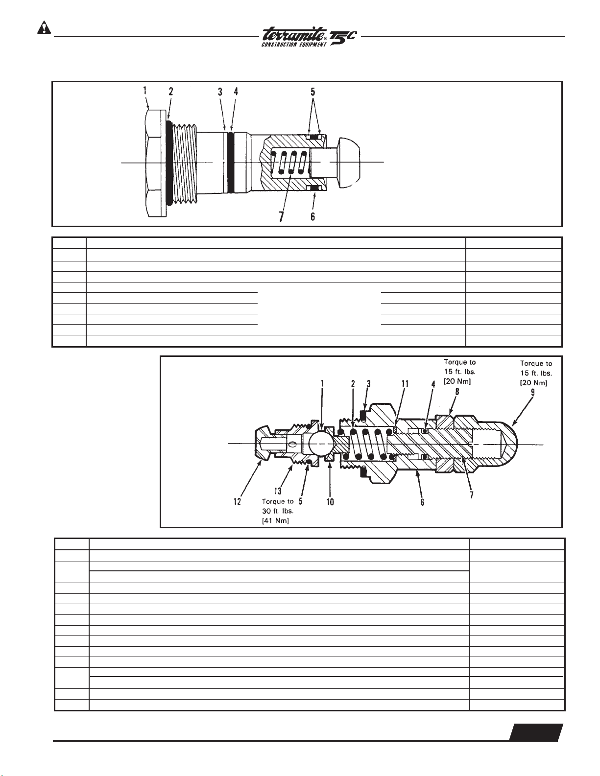
Load Check Plug Assembly
Torque Load Check Plug
Assembly to 20 ft. lbs. [27 Nm].
ITEM DESCRIPTION QTY. PER PLUG ASSEMBLY
Replacement Load Check Plug Assembly
Seal Kit, (Contains Items 2, 3, 4, 5 & 6)
1 Plug, Lift Check, Steel (Heavy Duty) 1
2 Seal, O-Ring 1
3 Washer, Back-Up, Outer 1
4 Seal, O-Ring, Outer 1
5 Washer, Back-Up, Inner 2
6 Seal, O-Ring 1
7 Spring, Lift Check 1
}
Not Sold Separately
High Pressure
Relief
For Installation: Torque Relief
Valves Assembly to 45 ft. lbs.
[61 Nm]
ITEM DESCRIPTION QTY. PER PLUG ASSEMBLY
1 Ball 1
Spring, Relief (Models SPK & SSK only)
2
Spring, Relief (Models SPK & SSK only)
1
3 Gasket, Relief Body 1
4 O-Ring, Adjusting Screw 1
5 O-Ring, Valve Seat 1
6 Body 1
7 Screw, Adjusting 1
8 Nut, Jam, Adjusting Screw 1
9 Nut, Acorn Cap 1
10 Guide, Spring 1
Washer, Spacer (SP) 1
11
Washer, Spacer (SPK) 2
12 Poppet, Check 1
13 Seat, Valve 1
 Loading...