

Page 1
Remote control
and monitoring server
PCS200
User manual
Version 1.1
TERRA
Page 2

www.terraelectronics.com
CONTENTS
1 Prod uct d escri ptio n _______________________________ 3
2 Safety instructions _______________________________ 3
3 Parameters _____________________________________ 3
3.1 Features ___________________________________ 3
4 External view and operating control _________________ 4
5 PCS200 control interface __________________________ 5
5.1 USB control ________________________________ 5
5.2 LCD display________________________________ 5
5.3 Keypad____________________________________ 5
5.4 “Addressed” indicator _______________________ 5
5.5 “Status” indicator ___________________________ 5
5.5 5.6 “Ground” clamp_____________________________ 5
5.7 230V~ 50 Hz power supply unit ________________ 5
5.8 Cooli ng fan_________________________________ 5
5.9 “Terra Bus” data bus connectors_______________ 5
5.10 UPS communication port ______________________ 6
5.11 Digital opto-isolated inputs____________________ 6
5.12 Digital relay outputs _________________________ 7
5.13 T emperature sensor _________________________ 7
5.14 Ethernet port _______________________________ 7
5.15 Secondary Ethernet port (optional) _____________ 7
5.16 Console port RS232 (debug)___________________ 7
6 Connecting to the network _________________________ 8
7 Default settings__________________________________ 8
8 PCS200 web control ______________________________ 8
8.1 Front page access ___________________________ 8
8.2 System management _________________________ 9
8.3 V ideo monitor______________________________ 10
8.4 Status ____________________________________ 12
8.5 I/O c ontrol ________________________________ 13
8.6 V iew configuration __________________________ 13
8.7 Headend description ________________________ 14
8.8 Time/Date ________________________________ 14
8.9 Network __________________________________ 15
8.10 Users ____________________________________ 16
8.11 V iew logs _________________________________ 16
8.12 Firmware update ___________________________ 17
8.13 Restart___________________________________ 17
8.14 LOGOUT _________________________________ 17
9 APPENDIX ____________________________________ 18
9.1 Networking over GSM cellular data network ____ 18
Page 3

Remote control and monitoring server PCS200
1 Product description
CMH WEB server is an optional device for T erra Bus managed devices monitoring and control.
Unit is considered as a master device on T erra Bus network as web-based frontend. Through the web server it is
possible to:
- monitor up to 255 devices connected to the data bus;
- view and change parameters on the individual devices;
- view device specific diagnostic information;
- operate advanced mode in terminal enabled devices;
- upgrade device firmware.
Unit is intended to be used together with MMH3000, CMH3000 and RMH3000 headends.
The product is intended for indoor usage only .
It is strictly recommended to feed AC power using UPS.
2 Safety instructions
The server is powered from mains 230 V~. This voltage is dangerous to life.
Any repairs must be done by a qualified personnel.
T o avoid the electric shock follow these instructions:
Do not remove the cover, without isolating the unit from the mains supply .
Do not plug the server into the mains supply if the power cord or plug are damaged.
Do not plug the server into the mains supply until all cables have been connected correctly.
To disconnect the server , disconnect plug from mains socket.
The mains socket must be easily accessible.
The server shall not be exposed to dripping or splashing water and no objects filled with liquids, such as vases,
shall be placed on it.
A void placing server next to central heating components and in areas of high humidity.
No naked flame sources, such as lighted candles, should be placed on server .
If the server has been kept in cold conditions for a long time, keep it in a warm room no less than 2 hours before
plugging into the mains.
The ventilation should not be impeded by covering the ventilation openings with items, such as newspapers,
table-cloths, curtains.
3 Parameters
Power consumption: 198...250V~ 50Hz 3.5W
W orking temperature 0
0
C...500C
Humidity ≤ 80%
3.1 Features:
Remote control for CMH3000, MMH3000 and RMH3000 headends;
Management from anywhere using a web browser;
Server and module software upgrade via HTTP;
Controls up to 255 modules;
Custom access levels for multiple users;
Integrated LCD and keyboard for configuration;
I/O control for external devices.
3
Page 4
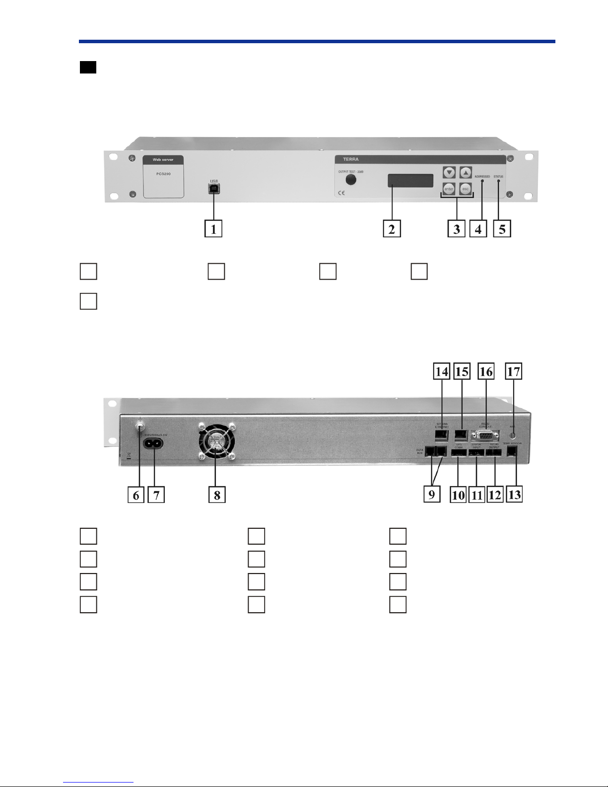
4 External view and operating control
Front view
5
4
1
USB control
2
LCD display
3
Keypad
4
“Addressed” indicator
5
“Status” indicator
6
“Ground” clamp
10
UPS communication port
14
Ethernet port
7
230V~ 50 Hz power supply input
11
Digital opto-isolated inputs
15
Secondary Ethernet port (optional)
8
Cooling fan
12
Digital relay outputs
16
Console port RS232 (debug)
9
“Terra bus” data bus connectors
13
Temperature sensor
17
Antenna port (not used)
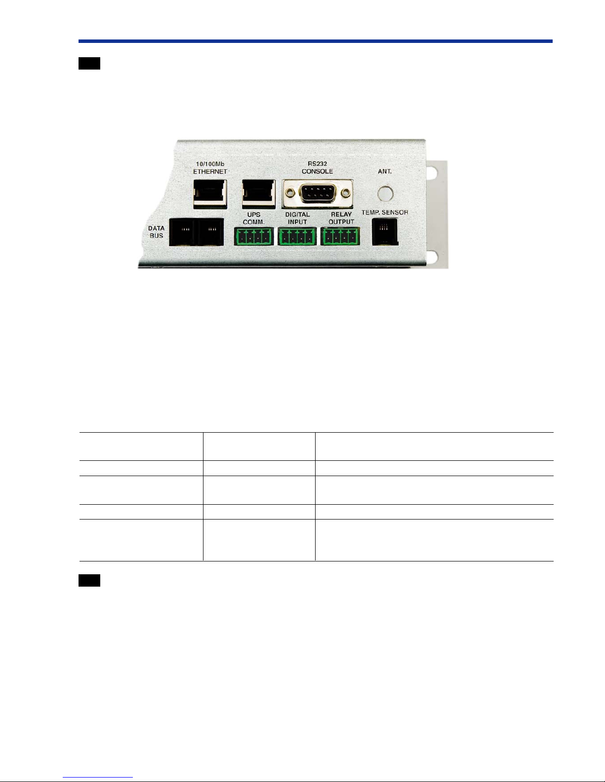
Back view
Page 5

5 PCS200 control interface
See “External view and operating control” section 4 for visual interface control locations.
5.1 USB control
Terra Bus data bus can be managed using front panel USB port along with proper PC software (e.g. T erra Link,
CMH Master). During USB control mode LCD panels shows system status: “USB CONTROL”, “ADDRESSED”
LED turns green and web server activity is suspended.
Note: To use USB port the driver must be installed. See supplied CD for more information.
5.2 LCD Display
Alphanumeric LCD display shows current server status as well as network settings.
5.3 Keypad
Basic network configuratin can be setup using onboard keypad. To move inside menu, press “>” or “<” buttons.
To activate selected submenu press “Enter”. “ESC” cancels any actions and returns to the default location (“System
status”).
Menu structure:
System Status > IP adress > Netmask > Gateway > Primary DNS > Secondary DNS > Reboot
T o change digital value press “Enter” and increase or decrease number above the marked using “>” or “<”
buttons. Selection is confirmed by pressing “Enter”.
Repeat this sequence untill the last number is set. After finishing the configuration select “Reboot” and press
“Enter”. System will reboot by indicating “System busy” in the “System status” screen. After changing status to “Ok”
system is running with new network settings.
5.4 “Addressed” indicator
Green “Addressed” indicator turns on when USB cable is connected.
5.5 “Status” indicator
Green“Status” indicator stays on as long as PCS200 server is powered up. Note that for PCS200 units with
firmware version below 2.00, “Status” LED could be red.
5.6 “Ground” clamp
It is highly recommended to have “Earth” safety terminal connected to “Ground” clamp to improve electrical
safety and EMI immunity.
5.7 230V ~50 Hz power supply input
5.8 Cooling fan
PCS200 has internal temperature sensor built in. Cooling fan is automatically started keeping device operating
safely if internal temperature gets above threshold limit.
5.9 “Terra Bus” data bus connectors
“Terra Bus” data bus is based on robust and industry standard RS485 bus specifications. Two parallel connectors
provided for user installation convenience. 4P4C “Terra Bus” cable is included in the package.
PCS200 “T erra Bus” cables must be unplugged if another master (PC or handheld) is used on the data bus.
192.168.0.99
5
Page 6
5.10 UPS communication port
This port has two inputs used to monitor and report UPS status.
Recommended mating terminal block connector:
T yco Electronics
p/n 284507-4 or p/n 284509-4
Pin-out:
pin 1 – 0V(logic ground)
pin 2 – PCS200 Input #4 (Battery Low)
pin 3 – 0V (logic ground)
pin 4 – PCS200 input #3 (Power Failure)
Input #3 and #4 status and log can be viewed with web interface by clicking on “I/O Control” link.
Most smart UPS devices have standard serial port (female D-SUB 9) with status information.
See connection table for PCS200 interfacing to smart UPS serial port.
PCS200 UPS COMM. UPS serial port Notes
pins (female D-SUB 9)
1 4 0V (logic ground)
2 5 Battery Low, open-collector output from UPS.
Normally low (0V), goes high when low battery .
3 4 0V (logic ground)
4 2 Power Failure, RS232 level output from UPS.
Normally RS232 low level (-12V), goes to
RS232 high level (+12V) when line power failure.
5.1 1 Digital opto-isolated inputs
There are two general purpose inputs.
Recommended mating terminal block connector:
T yco Electronics
p/n 284507-4 or p/n 284509-4
Pin-out:
Pin 1 – Input #2 Low-side
Pin 2 – Input #2 High-side
Pin 3 – Input #1 Low-side
Pin 4 – Input #1 High-side
Nominal input port voltage difference is +12V (operational from +5V to +20V).
Input #1 and #2 status and log can be viewed with web interface by clicking on “I/O Control” link.
See sample interface diagram below .
6
1234
1234 1234
11
11
1
22
22
2
33
33
3
44
44
4
Page 7

5.12 Digital relay outputs
There are two digital relay outputs. They could be used to control module power relays. This way user could
remotely restart station modules.
Recommended mating terminal block connector:
T yco Electronics
p/n 284507-4 or p/n 284509-4
Pin-out:
Pin 1 – Output #1 contact 1
Pin 2 – Output #1 contact 2
Pin 3 – Output #2 contact 1
Pin 4 – Output #2 contact 2
Relay output contacts electrical rating: 30VDC, 2A.
When power is off and while system is booting, both relay output contacts are NORMALL Y CLOSED. This way
using relay outputs to control system module power relays, system modules remain operational when PCS200 is
restarting.
When PCS200 has booted, outputs can be controlled by web interface (“I/O Control” link). Pressing “ON”
makes contacts closed, “OFF” - contacts open.
5.13 Temperature sensor
This interface allows to connect external temperature sensor (1-Wire compatible).
Pin-out:
Pin 1 - +5V power (supplied by PCS200)
Pin 2 - not used
Pin 3 - 1-Wire data bus
Pin 4 - 0V (logic ground)
Temperature sensors can be supplied as an option, please contact manufacturer for further information.
5.14 Ethernet port
This Ethernet port is used to connected PCS200 to the network. PCS200 supports 10/100Mbps Ethernet.
If PCS200 is placed behind a firewall or a router, make sure certain ports are open/forwarded (see “Connecting
to the network” section 6 for more details).
5.15 Secondary Ethernet port (optional)
This feature is enabled with PCS200 firmware versions 1.20 and above.
Secondary 10/100Mbps Ethernet port can be used to connect an IP streaming device like IP camera or video
server. Additional video/audio stream (TCP or UDP) ports needs to be open/forwarded if PCS200 is located
behind firewall/router . See “Video monitor” section 8.3 for more details.
5.16 Console port RS232 (debug)
This RS232 serial port (115200bps, 8-N-1) outputs some debug boot messages, and can be ignored by the user .
7
Page 8

6 Connecting to the network
To operate basic functions of PCS200 Ethernet and Data Bus cables must be connected.
• PCS200 can be operated using direct connection or pluged into Ethernet network. Ethernet socket
[14] is located on the back of PCS200.
• PCS200 must be the only master device on the T erra Bus. T wo parallel Data Bus sockets [9] are
located on the back of PCS200. No other handheld, USB-Terra Bus, Ethernet-T erra Bus device
can be used together. 4P4C cable is included in the package.
• If PCS200 is located behind a Firewall or router, following ports must be open or forwarded:
1. HTTP port 80 (TCP)
2. Extended HTML mode ports: 81 (TCP) and 1000 (TCP)
3. Advanced terminal mode: 2300 (TCP)
4. Other TCP or UDP ports if “Video monitor” feature is used. See “V ideo monitor” section 8.3 for
more information.
• If remote location with T erraBus managed devices and PCS200 server doesn’t have access to the
Internet, then GSM data networking option could be used as alternative solution. See Appendix –
“Networking over GSM cellular data network” section 9.1 for more details.
7 Default settings
IP: 192.168.0.99
Netmask: 255.255.255.0
Gateway: 192.168.0.1
User: terra
Password terra
Subrack count 2
8 PCS200 web control
8.1 Front page access
Device is shipped with default user “terra” and password “terra”. Administrator can enable and disable
access by adding users in web page “Users”.
8
Page 9

8.2 System management
T op of the webpage shows currently logged in user, PCS200 serial number and PCS200 firmware version.
If some modules aren’t visible or module firmware upgrade has been just performed, pressing “Rescan” link will
trigger PCS200 to scan all subrack addresses and update list of modules in System management page.
Terra Bus enabled modules are shown on the “SYSTEM MANAGEMENT” page:
Number of visible T erra Bus subracks can be set in “View configuration” page.
By pressing on the existing device, it is possible to view and change device’ s parameters.
After selecting desired settings, press button “Apply Changes” to activate configuration.
“Set Default Parameters” and “Firmware upgrade” options are only available in PCS200 with firmware
version of 1.20 and above.
“Set Default Parameters” button sets default module parameters. After operation completes, “SYSTEM
MANAGEMENT” page will load automatically . Please select same module to check its parameters again. If error
messages are shown in Diagnostics window , press “Reset module” following by “Refresh data” to update module
parameter view .
9
Page 10

“Firmware upgrade” button allows user to upgrade module firmware remotely. User must select module firmware
file(s) based on given format (e.g. firmware file 530XX_1_142.hex would fit in shown case).
Please note that module firmware upgrade might take several minutes and must not be interrupted
until it is complete otherwise module might get corrupted and unusable.
Both buttons “Set Default Parameters” and “Firmware upgrade” require ‘Administrator’ access level to operate
(see “Users” section 8.10 for more details).
8.3 V ideo monitor
This option is only available in PCS200 with firmware version of 1.20 and above.
“V ideo monitor” link allows to view video stream of an IP streaming device (IP camera, video server) connected
to a secondary Ethernet port [5.15].
IP streaming device must be configured with the following manual/static network settings before connecting to
PCS200 server:
IP address: 192.168.99.2
Subnet Mask: 255.255.255.0
Gateway: 192.168.99.1
Also check IP streaming device manufacturer documentation or configuration settings to find out which ports and
which protocols (TCP and/or UDP) are used for video/audio/control streams.
These ports must be open/forwarded in your firewall or router along with other PCS200 ports (see [6] “Connecting
to the network”).
Same streaming ports must be configured in PCS200 server internal firewall too. By default PCS200 has following
internal ports open:
80 TCP
5001 TCP, UDP
5002 TCP, UDP
5003 TCP, UDP
PCS200 server internal firewall ports are listed at the bottom of “V ideo monitor” page.
10
Page 11

In order to modify existing ports press “FireW all Ports” link. Following page will be displayed:
T o add a new port or modify existing port and protocol, enter port number, select TCP, UDP or both protocols
and press CHANGE. T o delete non-needed port, just enter port number, leave TCP and UDP selections blank and
press CHANGE.
Once all needed ports have been modified, press DONE to save new internal firewall configurations. And press
“Video monitor” link again.
Internal IP streaming device web interface should open up in the main frame. It is very likely that IP streaming
device will have some default login prompt, again check IP streaming device manufacturer documentation for login
user name and password.
11
Page 12

12
8.4 Status
Status submenu allows to automatically generate and send e-mail messages if temperature gets outside specified
limits or one of the inputs change. User can tick which parameters should be monitored and reported.
For this feature to work, email settings must be correctly set in “Network” page.
PCS200 has internal temperature sensor . External temperature is monitored only if external temperature sensor is
connected to connector [11]. Digital inputs are located in connector [9].
Page 13

13
8.5 I/O control
I/O control submenu display status of 2 relay outputs, 2 general purpose digital inputs and UPS state. Relay
outputs can control external devices.
To modify I/O description:
• Enter brief description in the text input area located near corresponding input/output.
• Press “Comment” button to save the information.
Events log will display:
• A relay state change by user .
• Digital input trigered by external device.
• Power line status change is reported by UPS.
8.6 View configuration
View configuration submenu allows user to choose number of subracks to be shown in “SYSTEM
MANAGEMENT” page. This parameter defines how many devices should be scanned by Terra Bus.
Recommendation: use only groups which are actually connected to the data bus. This improves scan time and
performance.
Page 14

14
8.7 Headend description
User may save any information related to connected headend. A three files can be uploaded for the future disposal.
File size is limitted up to 5 MB each.
T o upload file:
• Press “Browse” button.
• Locate file on the computer .
• Press “Send” button.
Upload time depends on file size and network conditions. System displays confirmation message if file is uploaded successfully.
T o download file:
• Press in the button named “Description #<1-3> <FILE>”.
• Confirm file download.
8.8 Time/Date
PCS200 internal battery-backed system clock can by adjusted by synchronizing with PC time in “Time/Date”
submenu page by pressing button: “SYNC”.
Page 15

15
8.9 Network
T o access web server it must be configured with proper TCP/IP settings. It can be done by:
• changing settings with onboard LCD panel
• filling up required values on the web page “Network”
Device is shipped with settings:
IP address: 192.168.0.99
Netmask: 255.255.255.0
If device is used not in the same subnet as the user’s workstation, “Gateway” IP address is also required
(e.g. 192.168.0.1). At least one DNS address should be supplied.
If email status reports are required (see “Status” page), then SMTP server and email addresses must be supplied.
Page 16

16
8.10 Users
Administrator can setup new accounts by supplying new user name, password and the access level. Any user who
has lower access level than administrator is unable to create new users.
There are two user access levels, ‘Administrator’ and ‘User’. ‘User’ access level is prevented from accessing
following functions:
• Upgrade module firmware
• Set default module parameters
• Add/delete/modify users
• V iew logs
• Upgrade PCS200 server firmware
8.11 View logs
Any successful or unsuccessful login of existing user will be show in the log file. Login time and remote user’s IP
address are saved. Administrator can clear access log by pressing “Clear ALL history”.
Page 17

17
8.12 Firmware update
Firmware update allows user to upload and upgrade PCS200 server firmware supplied by manufacturer.
PCS200 firmware version is printed on top of each page after serial number .
8.13 Restart
Reboots PCS200 server.
8.14 LOGOUT
Allows user to log out.
Page 18

9 APPENDIX
9.1 Networking over GSM cellular data network
Some remote locations where T erra Bus managed devices and PCS200 server is installed might not have Internet
access. Then GSM data networking option could be used as alternative as long as remote location is covered with
3G/EDGE/GPRS data service by the cellular provider . It’s recommended to use 3G or EDGE service to allow high
enough data rates for comfortable PCS200 control.
The user needs to obtain a SIM card with static IP address from local cellular operator. It might also be possible
to use SIM card with dynamic IP address, then dynamic DNS service (e.g. www.dyndns.org) could be used to
provide symbolic domain name. But it’ s important that cellular network provider SIM card ISP public IP would
match ISP local IP address, otherwise GSM router and PCS200 will not be visible and accessible from the Internet.
In some cases this could be requested as extra service from cellular network provider. It is recommended to consult
local network operator before ordering a SIM card or service.
If user is located in the area without internet access, then similarly 3G/EDGE router could be used to access
Internet and therefore gain access to PCS200.
18
Page 19

No additional PCS200 configurations are necessary , it can be left with default network settings:
IP: 192.168.0.99
Netmask: 255.255.255.0
Gateway: 192.168.0.1
Following parameters must be configured in 3G/EDGE router:
• APN (Access Point Name) and phone number (*99#), this information is supplied by GSM network
provider
• Router static WAN IP address, supplied by GSM network provider
• Router LAN settings:
o IP: 192.168.0.1
o Subnet: 255.255.255.0
• Router Ports forwarding to IP 192.168.0.99
o 80 TCP
o 81 TCP
o 1000 TCP
o 2300 TCP
o possibly additional IP streaming ports if “Video Monitor” feature is used (not recommended
because of high amount of network traffic and limited speed)
Internal tests and step by step procedure is based on using RUT100 - 3G Mobile Router manufactured by
T eltonika (
http://www.teltonika.lt). Although any other 3G/EDGE router with similar characteristics could be used
too.
RUT100 by default comes with LAN IP address of 192.168.0.1 and DHCP enabled. Connect your PC to
RUT100 for configuration, and login (default user: admin, password: admin01).
Go to “CONFIGURA TION” and enter APN and phone number. This information should be supplied by cellular
network provider when you purchase a SIM card.
19
Page 20

Then enter network settings as shown:
Next add following ports to forward to IP 192.168.0.99:
• 80 TCP
• 81 TCP
• 1000 TCP
• 2300 TCP
20
Page 21

Save all settings and reboot RUT100 router . Then connect RUT100 LAN port to PCS200 Ethernet port [14].
Enter provided static IP address (or dynamic DNS domain name) in the Internet Explorer address bar, and you
should see PCS200 server startup screen.
21
Page 22

TERRA UAB
Draugystes str. 22, LT-51256 Kaunas, Lithuania
Tel.: +370 37 - 31 34 44, fax: +370 37 - 31 35 55
E-mail: sales@terraelectronics.com
http://www.terraelectronics.com
 Loading...