

Page 1
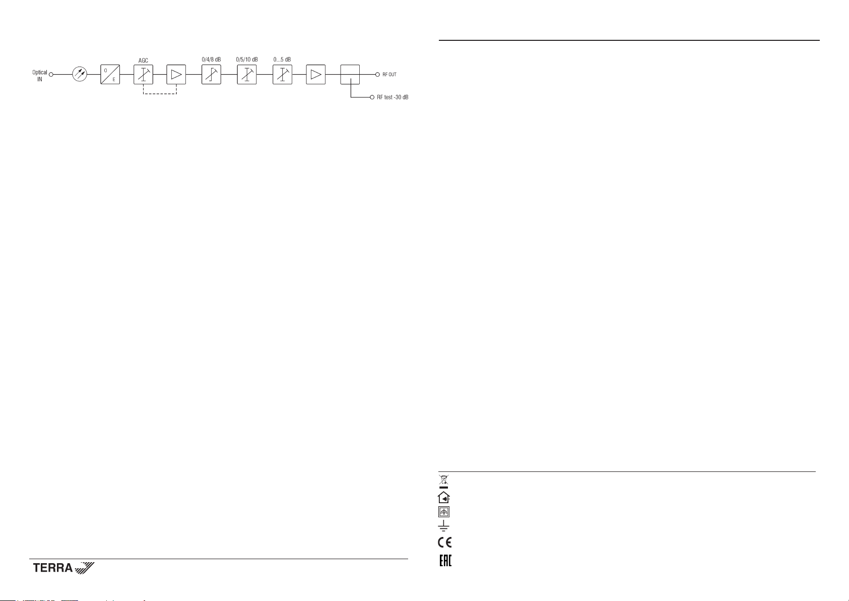
Structure diagram
Optical receivers OD005, OD005P
Product description
Optical receivers OD005, OD005P (in text – receiver) are intended to convert signals from optical to electrical. Devices
are equipped with Optical Level Control and optical input power indicator as well as bidirectional output test point to simplify
measurement, adjustment and troubleshooting.
OD005P receiver is powered from the mains 230 V~. OD005 receiver is powered from external +6 V DC power supply
unit (PSU) through F-type connector.
Devices are intended for indoor use only.
Suitable for moderate and tropical climates.
Safety instructions
Installation of the receiver must be done according IEC60728-11 and national safety standards.
Any repairs must be done by a qualied personnel.
The OD005P is powered from mains 230 V~. The voltage is dangerous to life.
The OD005 is powered from external +6 V DC power supply unit (PSU) through F-type connector. Output of PSU +6 V
must have a short circuit protection. Follow external PSU safety instructions during installation.
To ensure safe operation of the receivers follow these instructions:
do not remove the cover of the power supply section of OD005P, without disconnecting the unit from the mains supply;
do not plug the receiver into the mains supply if the power cord or plug are damaged;
do not plug the receiver OD005P and the PSU of OD005 into the mains supply until all cables have been connected correctly;
to disconnect the OD005P from the mains completely, disconnect plug from the mains socket;
to disconnect the OD005, disconnect the PSU from mains;
the mains socket must be easily accessible;
receiver shall not be exposed to dripping or splashing water and no objects lled with liquids, such as vases, shall be
placed on it;
avoid placing the receiver next to central heating components and in areas of high humidity;
no naked ame sources, such as lighted candles, should be placed on receiver;
if the receiver has been kept in cold conditions for a long time, keep it in a warm room no less than 2 hours before
plugging into the mains;
do not insert any objects into ventilation openings;
the ventilation should not be impeded by covering the ventilation openings with items, such as newspapers, table-cloths,
curtains;
mount the receiver in vertical position with RF connections underneath;
from top, front and bottom of installed receiver must be at least 10 cm free space.
An optical connector after disconnection emits optical radiation.
Avoid looking directly into beam, laser light can cause eye injuries and result in permanent loss of vision.
Draugystes str. 22, LT-51256 Kaunas, Lithuania, tel.: +370 37 - 31 34 44, fax: +370 37 - 31 35 55
E-mail: sales@terraelectronics.com, http://www.terraelectronics.com
Vers. 1.02
This product complies with the relevant clauses of the European Directive 2002/96/EC. The unit must be recycled
or discarded according to applicable local and national regulations.
Equipment intended for indoor usage only.
Equipment is double insulated from the mains, with functional earthing.
Functional earthing. Connect to the main potential equalization.
TERRA conrms, that this product is in accordance to following norms of EU: EMC norm EN50083-2, safety norm EN60065 and
RoHS norm EN50581.
TERRA confirms, that this product is in accordance with Custom Union Technical Regulations: “Electromagnetic compatibility of
technical equipment“ CU TR 020/2011, “On safety of low-voltage equipment“ CU TR 004/2011.
Page 2
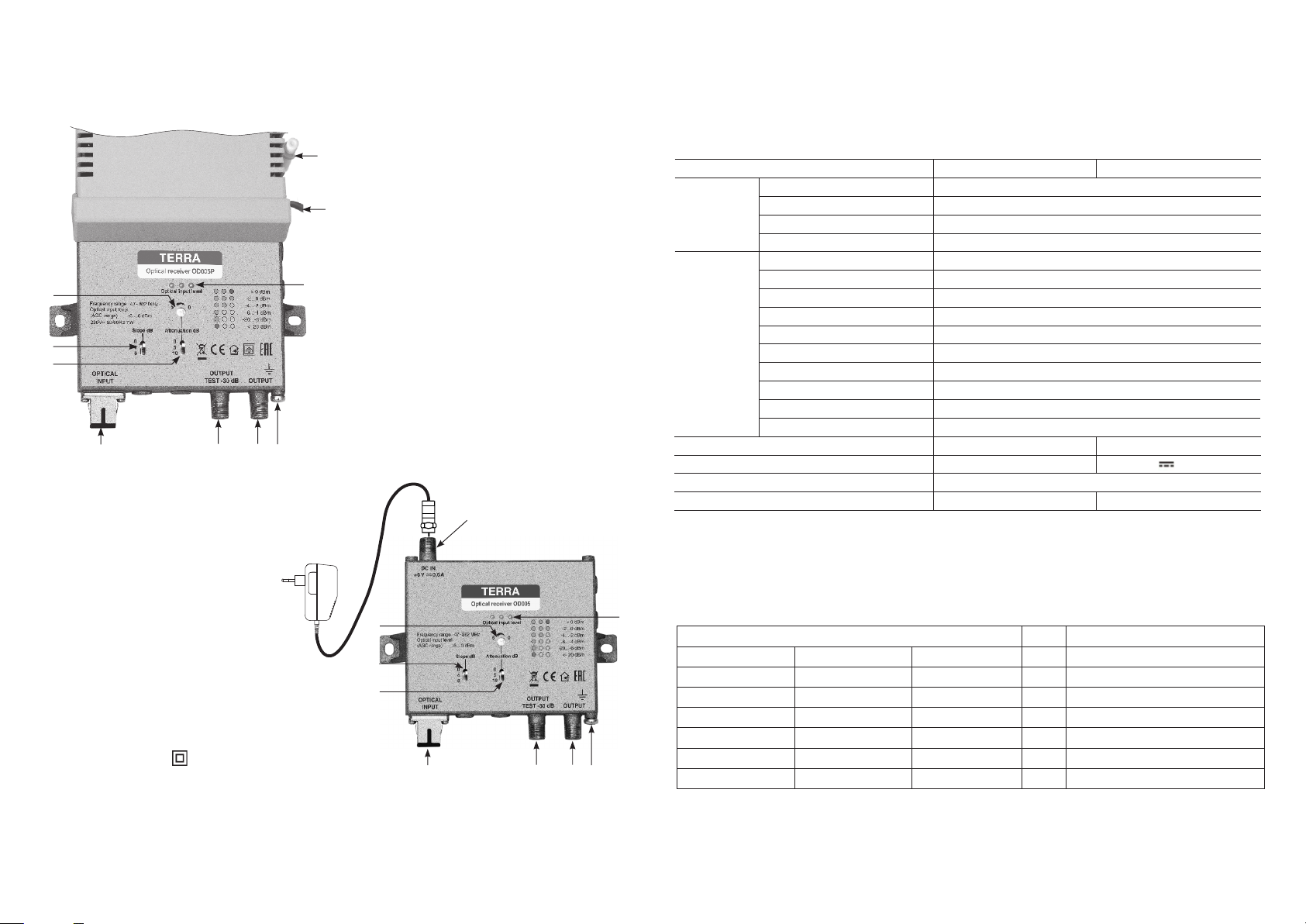
External view
1
2 3
4
OD005P
7
5
6
Requirements for external power supply unit
(PSU) for OD005
OD005 is powered from external 6V DC power supply unit.
Requirements:
• Output voltage: 6 V ± 5%
• Output current: > 0.7 A
• Output connector: type F, (+) inside
• Short circuit protection
• Double insulated (marked )
• Meet EN 55022 class B conducted emisions requirements,
measuring with grounded load
8
Power supply
+6 V DC
INSTALLATION INSTRUCTIONS
Read the product description and safety instruction rst.
The receiver should be mounted vertically with cable RF output underneath in order to ensure good ventilation conditions.
The receiver must be xed with steel screws Ø 4-5 mm. The screws are not included in a package.
Fiber installation should be done very carefully. Bending radius of bers must be not less 25 mm. All optical connectors
and adaptors should be cleaned before connecting them.
Plug the receiver into the mains after all cables have been connected correctly.
10
1. Optical input SC/APC
9
2. OUTPUT TEST-30 dB - RF output signal test point
(F socket)
3. OUTPUT - RF signal output connector (F socket)
4. Functional grounding clamp
5. 0 / 4 / 8 dB slope switch
6. 0 / 5 / 10 dB gain switch
7. 5 dB ne tuning gain regulator
8. 3 LED optical input power indicator
9. Power cord
10. Screwdriver
11. DC IN
OD005
11
Technical characteristics
Type OD005P OD005
Optical input optical wave lenght 1100-1600 nm
optical input level (AGC range) -6 ...0 dBm
optical return loss > 40 dB
noise current density ≤ 6.5 pA/√Hz
RF output frequency range 47-862 MHz
impedance 75 Ω
return loss ≥ 14 dB at 40 MHz-1.5 dB/octave
frequency response ± 0.75 dB
output level (AGC controlled, 4.9% OMI) 106 dBµV
output level (CTB, EN50083-3)* 107 dBµV (42 ch.)
output level (CSO , EN50083-3)* 107 dBµV (42 ch.)
interstage attenuator 0-15 dB
interstage equalizer 0/4/8 dB
loss in test point -30 ± 0.7 dB
Supply voltage limit values 198-250 V~ 50/60 Hz DC 6 V
Consumption 7 W 0.6 A
Operating temperature range -20o ÷ + 50o C
Dimensions/Weight (packed) 135x180x52 mm/0.7 kg 135x120x32 mm/0.34 kg
* output level (CTB, CSO) is measured with 8 dB interstage equalizer
Operating and adjusting
Optical level control (OLC) is active at optical input power -6 .. 0 dBm. The output level remains constant (adjusted by user
using discrete 0/5/10 dB switch and ne tuned with 0 .. 5 dB regulator) while optical input power uctuates in range of -6 .. 0 dBm.
7
5
6
1
2 3
8
4
The receiver owns optical input power indicator formed from 3 LED. Note the table below for detailed description.
Indication OLC Optical input power
Left LED Middle LED Right LED
Glowing red Not glowing Not glowing OFF < 20 dBm or optical signal is missing
Blinking green Not glowing Not glowing OFF - 20 .. - 6 dBm
Glowing green Not glowing Not glowing ON - 6 .. - 4 dBm
Glowing green Glowing green Not glowing ON - 4 .. - 2 dBm
Glowing green Glowing green Glowing green ON - 2 .. 0 dBm
Glowing green Glowing green Glowing red OFF > 0 dBm
 Loading...