

Page 1

MINI MODULAR HEADEND
MMH3000
BASE UNIT
UC360
User Manual
English
Vers. 1.01
Page 2

CONTENTS
MINI MODULAR HEADEND MMH3000 --------------------------------------------------------------------------------4
PRODUCT DESCRIPTION -----------------------------------------------------------------------------------------------4
SAFETY INSTRUCTIONS ------------------------------------------------------------------------------------------------4
ELECTROSTATIC DISCHARGE CAUTION --------------------------------------------------------------------------4
BASE UNIT UC360 -----------------------------------------------------------------------------------------------------------6
MOUNTING ----------------------------------------------------------------------------------------------------------------6
VENTILATION -------------------------------------------------------------------------------------------------------------6
EXTERNAL VIEW ---------------------------------------------------------------------------------------------------------7
POWER SUPPLY -----------------------------------------------------------------------------------------------------------8
CONNECTIONS BOARD -------------------------------------------------------------------------------------------------8
OUTPUT AMPLIFIER -----------------------------------------------------------------------------------------------------8
BASE UNIT NUMBER SETTING --------------------------------------------------------------------------------------8
TECHNICAL SPECIFICATIONS ----------------------------------------------------------------------------------------8
INSERTION/CHANGING OF THE MODULE ----------------------------------------------------------------------9
CONNECTIONS -------------------------------------------------------------------------------------------------------------- 10
CONTROL AND PROGRAMMING -------------------------------------------------------------------------------------- 11
HANDHELD CONTROL UNIT --------------------------------------------------------------------------------------- 11
PC CONNECTION ------------------------------------------------------------------------------------------------------- 12
SCOPE OF DELIVERY ------------------------------------------------------------------------------------------------------ 13
ACCESSORIES ---------------------------------------------------------------------------------------------------------------- 13
APPENDIX. TV CHANNELS ALLOCATION ---------------------------------------------------------------------- 14-15
www.terraelectronics.com
3
Page 3

MINI MODULAR HEADEND MMH3000
PRODUCT DESCRIPTION
Mini modular headend MMH3000 is compact solution for the distribution of DVB signals in SMATV
and CATV networks in analogue as well as in digital format.
The modern master-slave technology allows to build cost-effective analog TV installations and simplify
a circuitry of SAT IF and terrestrial input signal distribution.
Very flexible DVB-C and DVB-T transmitting system with minimal amount of the modules could be
done due to the original transport stream distribution system.
Communication over LAN, WAN or the Internet using bi-directional TSoIP module significantly extends
possibilities of the headend.
Up to 6 modules could be assembled into the UC360 base unit which incorporates a power supply unit,
RF amplifier and intelligent data bus. The data bus will automatically identify to the required USB link
software, any modules and their relevant position within the base unit with tuning and setting parameters.
Up to 16 base units can be connected together via a data bus.
Where 2 or more programmes are required from the same channel multiplex, the slave MPEG/VSB
modules are available which can be configured to tune additional programmes from a single digital channel.
The programming of MMH3000 can be made locally by handheld control unit by connecting the USB
software link using a PC or remotely through the internet or other communication line using advanced
control and monitoring software. It is also possible to “clone” headends from the settings saved in a
configuration file. The base unit can be installed into a standard 19" rack or stand-alone wall fixing by
reversing the mounting brackets 604.008.
The headend is intended for indoor use only.
SAFETY INSTRUCTIONS
Read the user manual first and observe the safety instructions.
Installation of the headend must be made in accordance with IEC60728-11 and local safety standards
by qualified personnel.
Any repairs must be done by an authorised technical professional staff.
The supplied mains cord is terminated at one end with a 2-pin connector, which must be inserted into
the mains input socket on the top panel of base unit before connecting to the mains supply.
Do not plug the headend into the mains supply if the power cord or plug is damaged.
To disconnect the headend, disconnect plug from mains socket.
The mains socket must be easily accessible.
Headend shall not be exposed to dripping or splashing water and no objects filled with liquids, such
as vases, shall be placed on it.
Avoid placing headend next to central heating components and in areas of high humidity.
No naked flame sources, such as lighted candles, should be placed on headend.
If the headend has been kept in cold conditions for a long time, keep it in a warm room no less than
2 hours before plugging into the mains.
Do not insert any objects into ventilation openings.
The ventilation should not be impeded by covering the ventilation openings with items, such as
newspapers, table-cloths, curtains.
Mount the headend in vertical position.
From top, front and bottom of installed headend must be at least 10 cm free space.
No service work during storm.
www.terraelectronics.com
4
Page 4
www.terraelectronics.com
5
caution!
Electrostatic discharge caution. The module contain electrostatic sensitive components. To
minimize electrostatic discharge, observe the following precautions:
- Do not remove module from their antistatic plastic bag until you are ready to install it
into the basic unit.
- Hold the module only by the front panel of module.
- Do not place the module on an unprotected surface. Immediately after you remove a
module from the basic unit, you must insert it into its antistatic plastic bag.
- When the module is not in use, keep it in their antistatic plastic bag.
- Do not ship or store module and basic unit near strong electrostatic, electromagnetic or
radioactive fields.
This product complies with the relevant clauses of the European Directive 2002/96/EC. The
unit must be recycled or discarded according to applicable local and national regulations.
Equipment intended for indoor usage only.
Equipment is double insulated from the mains, with functional earthing.
Functional earthing. Connect to the main potential equalization.
TERRA confirms, that this product is in accordance to following norms of EU: EMC norm
EN50083-2, safety norm EN60065 and RoHS norm EN50581.
TERRA confirms, that this product is in accordance with Custom Union Technical Regulations:
“Electromagnetic compatibility of technical equipment“ CU TR 020/2011, “On safety of low voltage equipment“ CU TR 004/2011.
TERRA confirms, that this product is in accordance with safety standard AS/NZS 60065 and
EMC standards of Australia.
Page 5
BASE UNIT UC360
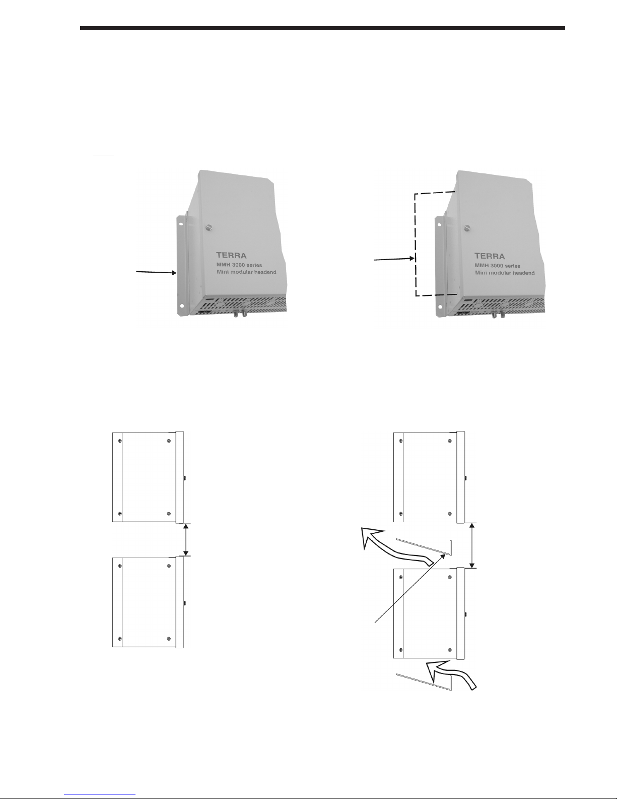
MOUNTING
The base unit is intended to be wall mounted or fitted in a 19" rack. The base unit must be mounted
vertically to allow the free flow of ventilation and allow heat to escape. The base unit must be fixed with
steel screws Ø 6 mm. The screws are not included in a package. Where 2 or more base units are mounted
above each other it is important to leave minimum 10-15 cm free space between the base units to ensure
normal ventilation. In case when ventilation panel 400.024 (see chapter ACCESSORIES) is used connect
grounding bus, data bus and RF cables at first.
Note: the total weight of a fully equipped UC360 is approximately 10 kg.
www.terraelectronics.com
6
VENTILATION
Mount in the vertical position only. In warm climatic conditions additional cooling may be necessary.
wall installation
19" rack installation with ventilation panel
Figure 1.
Figure 2.
Figure 3.
Figure 4.
the base unit is
delivered with fixing
brackets for wall
mounting
for assembling into
19" rack, replace to the
fixing brackets 604.008
as shown
minimum
gap 10 cm
minimum
gap 15 cm
ventilation
panel 400.024
see chapter
ACCESSORIES
Page 6

www.terraelectronics.com
7
EXTERNAL VIEW
The UC360 is the 5U height base unit. The UC360 has a built-in switch-mode power supply, RF output
amplifier and connections board. It has 6 identical slots for location of the modules.
Figure 5a. Front view
Figure 5b. Bottom view
1 - DIP switcher for setting of base unit number
2 - Power supply and RF output amplifier section
3 - RF LEVEL - output level regulator of the base unit
4 - RF combining section
5 - Connector for RF output of the modules
6 - Connector for data & DC bus feeding of the modules
7 - Connections board
8, 9 - PS CONNECT - holes for PC connection
10 - Removeable panel for V/A cable 400.38 connection
11a - HANDHELD/DATA BUS - data bus port for connection of the handheld PC100 or
extension cable 401.30
11b - DATA BUS - data bus port for connection of the data bus/USB interface UD104 extension
cable 401.30
12 - RF OUT - RF signal output connector
13 - RF TEST - RF output signal test point -20 dB
14 - stamped PCB module guides
15 - HANDHELD - data bus port for front connection of the handheld PC100
16 - Functional grounding clamp
17 - Mains connection port
18 - Plastic cover
19 - Stamped PCB module guides
Page 7

www.terraelectronics.com
8
POWER SUPPLY
Power supply is integrated into the UC360 base unit and powers any combination of the installed
modules.
CONNECTIONS BOARD
The connections board integrates the RF output of each module combiner and the DC & data distribution
bus (Figure 5a, pos. 7).
RF OUTPUT AMPLIFIER
RF output amplifier is intended to boost, regulate output level of UC360 and has a test port.
BASE UNIT NUMBER SETTING
Up to 16xUC360 base units can be linked together using the supplied data cables. Where more than one
UC360 is connected to the data bus, it is necessary to set each base unit's identity with a virtual number.
Each base unit number is set by the 5 positions DIP switch (Figure 5b, pos. 1). 4 positions (1, 2, 4, 8) are
for setting of the base unit number (Figure 6). Position 5 is switched ON only in the last base unit in data
bus extension line.
The table below shows how to set the base unit number.
Arms No
Last Subrack 1
2
4
8
Base unit No 1 2 3 4 5 6 7 8 9 10 11 12 13 14 15 16
The base unit identity number cannot be duplicated for 2 different base units.
On PC monitor the base unit will be indicated in order to base unit's number.
The base unit is supplied with the DIP switch settings for only 1 base unit Nr.1 (see Figure 6).
TECHNICAL SPECIFICATIONS
Figure 6.
Power supply
Input voltage limit values 180-250 V~ 50/60 Hz
Power consumption, max. 100 W
Output voltage 5.5 V 11 A max.
Output voltage for LNB powering
18 V & 0.6 A max.
via DVB-S module, switchable
RF combiner
Frequency range 47-862 MHz
Insertion loss 18 dB
Isolation > 20 dB
Output amplifier
Frequency range 47-862 MHz
Gain 13 dB
Gain adjustment 10 dB
Operating output level (6 modules) 95 dBµV
RF test -20 dB
General
Operating temperature range 00 ÷ +50 0C
PC connection RS485 and USB (optional) ports
Dimensions/Weight (packed) 374.5x235x181.5 mm/6.8 kg
Page 8

INSERTION/CHANGING OF THE MODULE
Disconnect the base unit from mains supply before insertion / changing of any module. Remove plastic
covers if necessary to allow entry of any aerial or LNB feeds (Figure 5a, pos.18, page 5).
www.terraelectronics.com
9
Figure 7.
Insertion module into the base unit:
- put the adapters on the tuner's ports (1)
- to align adapter's flat surfaces as shown in
picture before inserting module (2)
- place on serrated lock washer with
external teeth (4) on adapter (3);
- before pushing the module in direction
of bus bar carefully put the edges of
module PCB into grooved stamped guides
(Figure 5a, pos. 19);
- fasten each module by the fixing screws;
- place on washer (5) and screw on the
nut (6).
The modules will run in normal operation mode within 5-20 seconds of the mains supply being switched on.
Page 9

10
www.terraelectronics.com
CONNECTIONS
Top view
Input signal distributing by loop through
V/A cable connection to the modulators mt310X
Bottom view
cut off the panel
V/A cable 400.38
see chapter ACCESSORIES
Master - slave modules connection
← MPEG2 TS distribution cable 604.60
Flat cable 604.60 for connection of the
MPEG2 TS from 1 master module to 5 slave
modules is supplied with the base unit
UC360.
Using shears cut the flat cable carefully
to the required length depending on the
number of slave modules required.
3 slave modules
connected
to one master module
1 slave module
connected
to one master module
V/A source
Figure 8.
Figure 9.
Figure 10.
Figure 11.
Page 10

CONTROL AND PROGRAMMING
HANDHELD CONTROL UNIT
Maximum 2 base units could be controlled by the handheld control unit. For simultaneous control of the
modules placed on two base units, it is necessary to connect handheld control unit to port HANDHELD/
DATA BUS and connect port DATA BUS with port HANDHELD/DATA BUS into another base unit by
supplied cable 401.30 (Figure 12).
Do not connect handheld control unit while software control from PC is in operation.
Read handheld control unit PC100 user manual for detail information.
Bottom view
Handheld control unit PC100 connection
to the next base unit
PC100
Figure 12.
www.terraelectronics.com
Front view
11
PC100
Page 11

www.terraelectronics.com
12
PC CONNECTION
The system is controlled by TERRA Link or CMH Master software. The base units have be connected
in cascade by the data bus using supplied data extension cables 401.30.
NOTE! Do not connect handheld/data bus ports directly of two base units!
A maximum of 2 base units can be controlled by TERRA Link software and up to 16 base units by CMH
Master software can be managed through a single USB port. Before connecting the PC it is necessary to
ground all base units using the grounding clamps provided on the bottom side of the base unit (Figure
5b, pos. 16).
There are two ways to connect PC:
1) using the data bus/USB interface UD104 (it is recommend to use optically isolated);
2) using optional data bus/USB interface UD101 mounted inside UC360.
Additional equipment such as GSM terminal, printer etc. can be connected to a PC (for details see
manual of CMH Master software).
Data bus/USB interface connection
Bottom view
to the next base unit
Figure 13.
data bus/USB interface UD104
Front view
Do not connect
handheld/data bus ports
directly of two base units!
Page 12

www.terraelectronics.com
13
ACCESSORIES
Accessories are not included in scope of delivery, should be ordered separately.
1. V/A cable 400.38
3. Handheld PC100
4. USB interface UD104
Supplied together with
software Terra Link
SCOPE OF DELIVERY
1. User manual UC360
2. Base unit UC360 - 1 pc
3. Power cord - 1 pc
4. Data bus extension cable 401.30 - 1 pc
5. MPEG2 TS distribution cable 604.60 - 1 pc
6. Load 75 Ohm - 1 pc
8. CMH Master - advanced software for local
or remote control up to 16 base units. For
more detail information, please visit www.
terraelectronics.com
6. Ventilation panel 400.024
5. USB interface UD101
Supplied together with
software Terra Link
7. Fixing brackets 604.008
for assembling into 19" rack
2. V/A cable 404.38
Page 13

www.terraelectronics.com
14
Standard I/South Africa
TV Channel Frequency, Central Video carrier, Audio carrier,
band No. MHz frequency, MHz MHz
MHz
III 4 174-182 178 175.25 181.25
5 182-190 186 183.25 189.25
6 190-198 194 191.25 197.25
7 198-206 202 199.25 205.25
8 206-214 210 207.25 213.25
9 214-222 218 215.25 221.25
10 222-230 226 223.25 229.25
11 230-238 234 231.25 237.25
13 246-254 250 247.25 253.25
TV Channel Frequency, Central Video carrier, Audio carrier,
band No. MHz frequency, MHz MHz
MHz
I L 02 49-57.00 53 55.75 49.25
L 03 53.75-61.75 57.75 60.50 54.00
L 04 57.00-65.00 61 63.75 57.25
III L 05 174.75-182.75 178.75 176.00 182.50
L 06 182.75-190.75 186.75 184.00 190.50
L 07 190.75-198.75 194.75 192.00 198.50
L 08 198.75-206.75 202.75 200.00 206.50
L 09 206.75-214.75 210.75 208.00 214.50
L 10 214.75-222.75 218.75 216.00 222.50
Inter- B 115.5-123.5 119.5 116.75 123.25
bande C 127.5-135.5 131.5 128.75 135.25
D 139.5-147.5 143.5 140.75 147.25
E 151.5-159.5 155.5 152.75 159.25
F 163.5-171.5 167.5 164.75 171.25
G 175.5-183.5 179.5 176.75 183.25
H 187.5-195.5 191.5 188.75 195.25
I 199.5-207.5 203.5 200.75 207.25
J 211.5-219.5 215.5 212.75 219.25
K 223.5-231.5 227.5 224.75 231.25
L 235.5-243.5 239.5 236.75 243.25
M 247.5-255.5 251.5 248.75 255.25
N 259.5-267.5 263.5 260.75 267.25
O 271.5-279.5 275.5 272.75 279.25
P 283.5-291.5 287.5 284.75 291.25
Standard L/France
Standard B/Australia
TV Channel Frequency, Central Video carrier, Audio carrier,
band No. MHz frequency, MHz MHz
MHz
I 0 45-52 48.5 46.25 51.75
1 56-63 59.5 57.25 62.75
2 63-70 66.5 64.25 69.75
II 3 85-92 88.5 86.25 91.75
4 97-101 99 95.25 100.75
5 101-108 104.5 102.25 107.75
5a 137-144 140.5 138.25 143.75
VHF S3 118-125 121.5 119.25 124.75
Mid- S4 125-132 128.5 126.25 131.75
band S5 132-139 135.5 133.25 138.75
S6 139-146 142.5 140.25 145.75
S7 146-153 149.5 147.25 152.75
S8 153-160 156.5 154.25 159.75
S9 160-167 163.5 161.25 166.75
S10 167-174 170.5 168.25 173.75
III 6 174-181 177.5 175.25 180.75
7 181-188 184.5 182.25 187.75
8 188-195 191.5 189.25 194.75
9 195-202 198.5 196.25 201.75
10 208-215 211.5 209.25 214.75
11 215-222 218.5 216.25 221.75
12 223-230 226.5 224.25 229.75
TV Channel Frequency, Central Video carrier, Audio carrier,
band No. MHz frequency, MHz MHz
MHz
I 1 48.5-56.5 52.5 49.75 56.25
2 58-66 62 59.25 65.75
II 3 76-84 80 77.25 83.75
4 84-92 88 85.25 91.75
5 92-100 96 93.25 99.75
SR1 SR1 110-118 114 111.25 117.75
SR2 118-126 122 119.25 125.75
SR3 126-134 130 127.25 133.75
SR4 134-142 138 135.25 141.75
SR5 142-150 146 143.25 149.75
SR6 150-158 154 151.25 157.75
SR7 158-166 162 159.25 165.75
SR8 166-174 170 167.25 173.75
III 6 174-182 178 175.25 181.75
7 182-190 186 183.25 189.75
8 190-198 194 191.25 197.75
9 198-206 202 199.25 205.75
10 206-214 210 207.25 213.75
11 214-222 218 215.25 221.75
12 222-230 226 223.25 229.75
SR2 SR11 230-238 234 231.25 237.75
SR12 238-246 242 239.25 245.75
SR13 246-254 250 247.25 253.75
SR14 254-262 258 255.25 261.75
SR15 262-270 266 263.25 269.75
SR16 270-278 274 271.25 277.75
SR17 278-286 282 279.25 285.75
SR18 286-294 290 287.25 293.75
SR3 S19 294-302 298 295.25 301.75
S20 302-310 306 303.25 309.75
S21 310-318 314 311.25 317.75
S22 318-326 322 319.25 325.75
S23 326-334 330 327.25 333.75
S24 334-342 338 335.25 341.75
S25 342-350 346 343.25 349.75
S26 350-358 354 351.25 357.75
S27 358-366 362 359.25 365.75
S28 366-374 370 367.25 373.75
S29 374-382 378 375.25 381.75
S30 382-390 386 383.25 389.75
S31 390-398 394 391.25 397.75
S32 398-406 402 399.25 405.75
S33 406-414 410 407.25 413.75
S34 414-422 418 415.25 421.75
S35 422-430 426 423.25 429.75
S36 430-438 434 431.25 437.75
S37 438-446 442 439.25 445.75
S38 446-454 450 447.25 453.75
S39 454-462 458 455.25 461.75
S40 462-470 466 463.25 469.75
Standard D/OIRT
TV Channel Frequency, Central Video carrier, Audio carrier,
band No. MHz frequency, MHz MHz
MHz
Hyper- S11 230-237 233.5 231.25 236.75
band S12 237-244 240.5 238.25 243.75
S13 244-251 247.5 245.25 250.75
S14 251-258 254.5 252.25 257.75
S15 258-265 261.5 259.25 264.75
S16 265-272 268.5 266.25 271.75
S17 272-279 275.5 273.25 278.75
S18 279-286 282.5 280.25 285.75
S19 286-293 289.5 287.25 292.75
S20 293-300 296.5 294.25 299.75
S21 302-309 305.5 303.25 308.75
S22 309-316 312.5 310.25 315.75
S23 316-323 319.5 317.25 322.75
S24 323-330 326.5 324.25 329.75
S25 330-337 333.5 331.25 336.75
S26 337-344 340.5 338.25 343.75
S27 344-351 347.5 345.25 350.75
S28 351-358 354.5 352.25 357.75
S29 358-365 361.5 359.25 364.75
S30 365-372 368.5 366.25 371.75
S31 372-379 375.5 373.25 378.75
S32 379-386 382.5 380.25 385.75
S33 386-393 389.5 387.25 392.75
S34 393-400 396.5 394.25 399.75
S35 400-407 403.5 401.25 406.75
S36 407-414 410.5 408.25 413.75
S37 414-421 417.5 415.25 420.75
S38 421-428 424.5 422.25 427.75
S39 428-435 431.5 429.25 434.75
S40 435-442 438.5 436.25 441.75
S41 442-449 445.5 443.25 448.75
APPENDIX
TV CHANNELS ALLOCATION
Page 14

15
www.terraelectronics.com
Standard K/OIRT, G/CCIR, I, L, H
TV Channel Frequency, Central Video carrier, Audio carrier, Audio carrier, Audio carrier,
band No. MHz frequency, MHz MHz MHz MHz
MHz Standard G, H Standard I Standard K, L
IV 21 470-478 474 471.25 476.75 477.25 477.75
22 478-486 482 479.25 484.75 485.25 485.75
23 486-494 490 487.25 492.75 493.25 493.75
24 494-502 498 495.25 500.75 501.25 501.75
25 502-510 506 503.25 508.75 509.25 509.75
26 510-518 514 511.25 516.75 517.25 517.75
27 518-526 522 519.25 524.75 525.25 525.75
28 526-534 530 527.25 532.75 533.25 533.75
29 534-542 538 535.25 540.75 541.25 541.75
30 542-550 546 543.25 548.75 549.25 549.75
31 550-558 554 551.25 556.75 557.25 557.75
32 558-566 562 559.25 564.75 565.25 565.75
33 566-574 570 567.25 572.75 573.25 573.75
34 574-582 578 575.25 580.75 581.25 581.75
35 582-590 586 583.25 588.75 589.25 589.75
36 590-598 594 591.25 596.75 597.25 597.75
37 598-606 602 599.25 604.75 605.25 605.75
V 38 606-614 610 607.25 612.75 613.25 613.75
39 614-622 618 615.25 620.75 621.25 621.75
40 622-630 626 623.25 628.75 629.25 629.75
41 630-638 634 631.25 636.75 637.25 637.75
42 638-646 642 639.25 644.75 645.25 645.75
43 646-654 650 647.25 652.75 653.25 653.75
44 654-662 658 655.25 660.75 661.25 661.75
45 662-670 666 663.25 668.75 669.25 669.75
46 670-678 674 671.25 676.75 677.25 677.75
47 678-686 682 679.25 684.75 685.25 685.75
48 686-694 690 687.25 692.75 693.25 693.75
49 694-702 698 695.25 700.75 701.25 701.75
50 702-710 706 703.25 708.75 709.25 709.75
51 710-718 714 711.25 716.75 717.25 717.75
52 718-726 722 719.25 724.75 725.25 725.75
53 726-734 730 727.25 732.75 733.25 733.75
54 734-742 738 735.25 740.75 741.25 741.75
55 742-750 746 743.25 748.75 749.25 749.75
56 750-758 754 751.25 756.75 757.25 757.75
57 758-766 762 759.25 764.75 765.25 765.75
58 766-774 770 767.25 772.75 773.25 773.75
59 774-782 778 775.25 780.75 781.25 781.75
60 782-790 786 783.25 788.75 789.25 789.75
61 790-798 794 791.25 796.75 797.25 797.75
62 798-806 802 799.25 804.75 805.25 805.75
63 806-814 810 807.25 812.75 813.25 813.75
64 814-822 818 815.25 820.75 821.25 821.75
65 822-830 826 823.25 828.75 829.25 829.75
66 830-838 834 831.25 836.75 837.25 837.75
67 838-846 842 839.25 844.75 845.25 845.75
68 846-854 850 847.25 852.75 853.25 853.75
69 854-862 858 855.25 860.75 861.25 861.75
TV Channel Frequency, Central Video carrier, Audio carrier,
band No. MHz frequency, MHz MHz
MHz
IV 20 470-477 473.5 471.25 476.75
21 477-484 480.5 478.25 483.75
22 484-491 487.5 485.25 490.75
23 491-498 494.5 492.25 497.75
24 498-505 501.5 499.25 504.75
25 505-512 508.5 506.25 511.75
26 512-519 515.5 513.25 518.75
27 519-526 522.5 520.25 525.75
28 526-533 529.5 527.25 532.75
29 533-540 536.5 534.25 539.75
30 540-547 543.5 541.25 546.75
31 547-554 550.5 548.25 553.75
32 554-561 557.5 555.25 560.75
33 561-568 564.5 562.25 567.75
34 568-575 571.5 569.25 574.75
35 575-582 578.5 576.25 581.75
V 36 582-589 585.5 583.25 588.75
37 589-596 592.5 590.25 595.75
38 596-603 599.5 597.25 602.75
39 603-610 606.5 604.25 609.75
40 610-617 613.5 611.25 616.75
41 617-624 620.5 618.25 623.75
42 624-631 627.5 625.25 630.75
43 631-638 634.5 632.25 637.75
44 638-645 641.5 639.25 644.75
45 645-652 648.5 646.25 651.75
46 652-659 655.5 653.25 658.75
47 659-666 662.5 660.25 665.75
48 666-673 669.5 667.25 672.75
49 673-680 676.5 674.25 679.75
50 680-687 683.5 681.25 686.75
51 687-694 690.5 688.25 693.75
52 694-701 697.5 695.25 700.75
53 701-708 704.5 702.25 707.75
54 708-715 711.5 709.25 714.75
55 715-722 718.5 716.25 721.75
56 722-729 725.5 723.25 728.75
57 729-736 732.5 730.25 735.75
58 736-743 739.5 737.25 742.75
59 743-750 746.5 744.25 749.75
60 750-757 753.5 751.25 756.75
61 757-764 760.5 758.25 763.75
62 764-771 767.5 765.25 770.75
63 771-778 774.5 772.25 777.75
64 778-785 781.5 779.25 784.75
65 785-792 788.5 786.25 791.75
66 792-799 795.5 793.25 798.75
67 799-806 802.5 800.25 805.75
68 806-813 809.5 807.25 812.75
69 813-820 816.5 814.25 819.75
70 820-827 823.5 821.25 826.75
71 827-834 830.5 828.25 833.75
72 834-841 837.5 835.25 840.75
73 841-848 844.5 842.25 847.75
74 848-855 851.5 849.25 854.75
75 855-862 858.5 856.25 861.75
Standard B/Australia
Standard B/CCIR
TV Channel Frequency, Central Video carrier, Audio carrier,
band No. MHz frequency, MHz MHz
MHz
I E1* 44-51 47.5 45.25 50.75
E2 47-54 50.5 48.25 53.75
E3 54-61 57.5 55.25 60.75
E4 61-68 64.5 62.25 67.75
S1 S3 118-125 121.5 119.25 124.75
S4 125-132 128.5 126.25 131.75
S5 132-139 135.5 133.25 138.75
S6 139-146 142.5 140.25 145.75
S7 146-153 149.5 147.25 152.75
S8 153-160 156.5 154.25 159.75
S9 160-167 163.5 161.25 166.75
S10 167-174 170.5 168.25 173.75
III E5 174-181 177.5 175.25 180.75
E6 181-188 184.5 182.25 187.75
E7 188-195 191.5 189.25 194.75
E8 195-202 198.5 196.25 201.75
E9 202-209 205.5 203.25 208.75
E10 209-216 212.5 210.25 215.75
E11 216-223 219.5 217.25 222.75
E12 223-230 226.5 224.25 229.75
S2 S11 230-237 233.5 231.25 236.75
S12 237-244 240.5 238.25 243.75
S13 244-251 247.5 245.25 250.75
S14 251-258 254.5 252.25 257.75
S15 258-265 261.5 259.25 264.75
TV Channel Frequency, Central Video carrier, Audio carrier,
band No. MHz frequency, MHz MHz
MHz
S16 265-272 268.5 266.25 271.75
S17 272-279 275.5 273.25 278.75
S18 279-286 282.5 280.25 285.75
S19 286-293 289.5 287.25 292.75
S20 293-300 296.5 294.25 299.75
S3 S21 302-310 306 303.25 308.75
S22 310-318 314 311.25 316.75
S23 318-326 322 319.25 324.75
S24 326-334 330 327.25 332.75
S25 334-342 338 335.25 340.75
S26 342-350 346 343.25 348.75
S27 350-358 354 351.25 356.75
S28 358-366 362 359.25 364.75
S29 366-374 370 367.25 372.75
S30 374-382 378 375.25 380.75
S31 382-390 386 383.25 388.75
S32 390-398 394 391.25 396.75
S33 398-406 402 399.25 404.75
S34 406-414 410 407.25 412.75
S35 414-422 418 415.25 420.75
S36 422-430 426 423.25 428.75
S37 430-438 434 431.25 436.75
S38 438-446 442 439.25 444.75
* New Zeland Ch.1
Page 15

TERRA UAB
Draugystes str. 22, LT-51256 Kaunas, Lithuania
Tel.: +370 37 - 31 34 44, fax: +370 37 - 31 35 55
E-mail: sales@terraelectronics.com
http://www.terraelectronics.com
 Loading...