

Page 1

9
1
Splitband amplier HS005L
Product description
A splitband amplier is intended for amplifying cable TV, terrestrial TV and FM radio signals.
There is a possibility to adjust the gain of the amplier separately in VHF and UHF bands.
The amplier can provide power (+12 V) to external equipment through RF IN connector (1).
The UHF sub-band of the amplier has integrated 30 dB LTE signal suppression lter.
The amplier is intended for indoor use only.
Safety instructions
Installation of the amplier must be done according IEC60728-11 and national safety standards.
The amplier is powered from mains 230 V~. This voltage is dangerous to life.
Any repairs must be done by a qualied personnel.
Do not remove the cover of the power supply section, without disconnecting the unit from the mains supply.
Do not plug the amplier into the mains supply if the power cord or plug is damaged.
Do not plug the amplier into the mains supply until all cables have been connected correctly.
To disconnect the amplier from the mains completely, disconnect plug from the mains socket.
The mains socket must be easily accessible.
The amplier shall not be exposed to dripping or splashing water and no objects lled with liquids, such as vases, shall
be placed on it.
Avoid placing amplier next to central heating components and in areas of high humidity.
No naked ame sources, such as lighted candles, should be placed on amplier.
If the amplier has been kept in cold conditions for a long time, keep it in a warm room no less than 2 hours before
plugging into the mains.
Do not insert any objects into ventilation openings;
The ventilation should not be impeded by covering the ventilation openings with items, such as newspapers, table-cloths,
curtains.
Mount the amplier in vertical position with RF input connector underneath.
From top, front and bottom of installed amplier must be at least 10 cm free space.
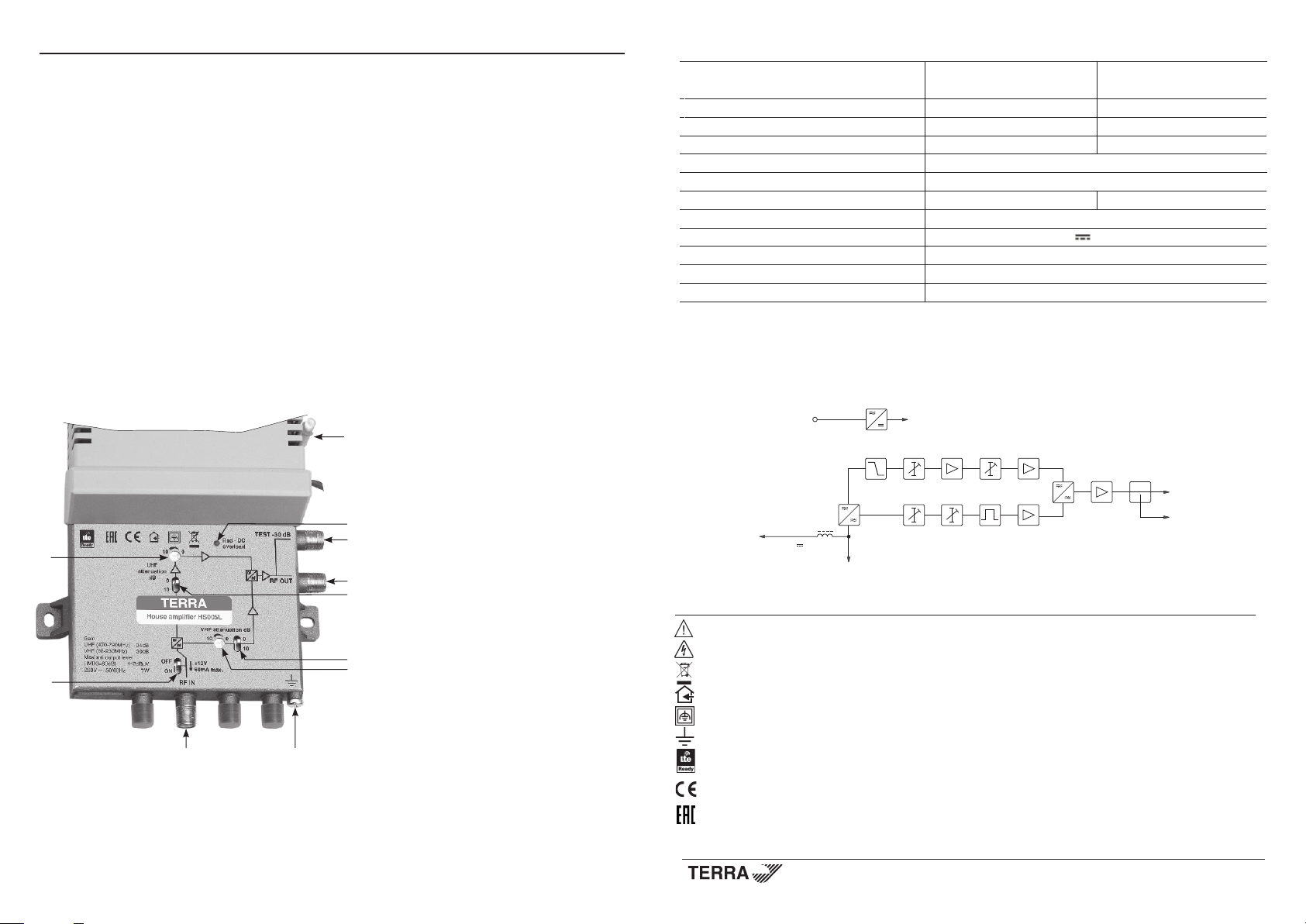
External view
11
Technical characteristics
Frequency range VHF UHF
88-230 MHz 470-790 MHz
Gain 30 dB 34 dB
Flatness ± 1 dB ± 0.5 dB
Gain adjustment 20 dB 20 dB
Maximal output level IMD3=60 dB (DIN45004B) 115 dBµV, IMD3=60 dB 112 dBµV
Input and output return loss > 10 dB
Noise gure < 5 dB < 4 dB (700 MHz)
Output test point -30 dB
DC feeding for external equipment 12 V 60 mA max.
Supply voltage limit values, power consumption* 198-250 V~ 50/60 Hz 7 W
Operating temperature range -20o ÷ +50o C
Dimensions/Weight (packed) 135x180x52 mm/0.7 kg
* with external DC loading
Structure diagram
230 V~
DC
-10/0 dB
LTE
0ø 10 dB-
10
1. RF IN - RF signal input connector
2
6
2. RF OUT - RF signal output connector
3. Test point -30 dB
3
4, 5. 10 dB gain switches (10 dB attenuation
for each sub-band)
4
6,7. 10 dB ne tuning gain regulators
for each sub-band
8. Switch to turn on/off the power feed for external
equipment
5
9. Functional ground clamp
7
8
10. Powering indicator
11. Screwdriver
Vers. 1.03
INSTALLATION INSTRUCTIONS
Read the product description and safety instruction rst.
Installation of system according standard IEC60728-11 ensures safety of personnel and prevents apparatus against
damaging due to lightning or other sources of overvoltage surges.
Gain of every sub-band can be adjusted with screwdriver (11). The gain increases up to 10 dB by ne turning regulators
(6, 7) clockwise in every sub-band and an additional 10 dB by switching switches (4, 5) in VHF and UHF bands.
Power feed for external equipment is turned on and off by switch (8). It has short circuit and overload protection. In normal
conditions powering indicator (10) glows green. If short circuit or overload in external powered equipment is detected - glows red.
UHF
VHF
DC 12 V 60 mA, max.
RF IN
Caution.
Risk of electric shock.
This product complies with the relevant clauses of the European Directive 2002/96/EC. The unit must be recycled or discarded
according to applicable local and national regulations.
Equipment intended for indoor usage only.
Equipment is double insulated from the mains, with functional earthing.
Functional earthing. Connect to the main potential equalization.
The device has integrated LTE lter.
TERRA conrms, that this product is in accordance to following norms of EU: EMC norm EN50083-2, safety norm EN60065
and RoHS norm EN50581.
TERRA conrms, that this product is in accordance with Custom Union Technical Regulations: “Electromagnetic compatibility
of technical equipment“ CU TR 020/2011, “On safety of low-voltage equipment“ CU TR 004/2011.
0ø 10 dB-
-10/0 dB
RF OUT
test
-30 dB
Draugystes str. 22, LT-51256 Kaunas, Lithuania, tel.: +370 37 - 31 34 44, fax: +370 37 - 31 35 55
E-mail: sales@terraelectronics.com, http://www.terraelectronics.com
Page 2
9
1
Splitband amplier HS005L
Product description
A splitband amplier is intended for amplifying cable TV, terrestrial TV and FM radio signals.
There is a possibility to adjust the gain of the amplier separately in VHF and UHF bands.
The amplier can provide power (+12 V) to external equipment through RF IN connector (1).
The UHF sub-band of the amplier has integrated 30 dB LTE signal suppression lter.
The amplier is intended for indoor use only.
Safety instructions
Installation of the amplier must be done according IEC60728-11 and national safety standards.
The amplier is powered from mains 230 V~. This voltage is dangerous to life.
Any repairs must be done by a qualied personnel.
Do not remove the cover of the power supply section, without disconnecting the unit from the mains supply.
Do not plug the amplier into the mains supply if the power cord or plug is damaged.
Do not plug the amplier into the mains supply until all cables have been connected correctly.
To disconnect the amplier from the mains completely, disconnect plug from the mains socket.
The mains socket must be easily accessible.
The amplier shall not be exposed to dripping or splashing water and no objects lled with liquids, such as vases, shall
be placed on it.
Avoid placing amplier next to central heating components and in areas of high humidity.
No naked ame sources, such as lighted candles, should be placed on amplier.
If the amplier has been kept in cold conditions for a long time, keep it in a warm room no less than 2 hours before
plugging into the mains.
Do not insert any objects into ventilation openings;
The ventilation should not be impeded by covering the ventilation openings with items, such as newspapers, table-cloths,
curtains.
Mount the amplier in vertical position with RF input connector underneath.
From top, front and bottom of installed amplier must be at least 10 cm free space.
External view
11
Technical characteristics
Frequency range VHF UHF
88-230 MHz 470-790 MHz
Gain 30 dB 34 dB
Flatness ± 1 dB ± 0.5 dB
Gain adjustment 20 dB 20 dB
Maximal output level IMD3=60 dB (DIN45004B) 115 dBµV, IMD3=60 dB 112 dBµV
Input and output return loss > 10 dB
Noise gure < 5 dB < 4 dB (700 MHz)
Output test point -30 dB
DC feeding for external equipment 12 V 60 mA max.
Supply voltage limit values, power consumption* 198-250 V~ 50/60 Hz 7 W
Operating temperature range -20o ÷ +50o C
Dimensions/Weight (packed) 135x180x52 mm/0.7 kg
* with external DC loading
Structure diagram
230 V~
DC
-10/0 dB
LTE
0ø 10 dB-
10
1. RF IN - RF signal input connector
2
6
2. RF OUT - RF signal output connector
3. Test point -30 dB
3
4, 5. 10 dB gain switches (10 dB attenuation
for each sub-band)
4
6,7. 10 dB ne tuning gain regulators
for each sub-band
8. Switch to turn on/off the power feed for external
equipment
5
9. Functional ground clamp
7
8
10. Powering indicator
11. Screwdriver
Vers. 1.03
INSTALLATION INSTRUCTIONS
Read the product description and safety instruction rst.
Installation of system according standard IEC60728-11 ensures safety of personnel and prevents apparatus against
damaging due to lightning or other sources of overvoltage surges.
Gain of every sub-band can be adjusted with screwdriver (11). The gain increases up to 10 dB by ne turning regulators
(6, 7) clockwise in every sub-band and an additional 10 dB by switching switches (4, 5) in VHF and UHF bands.
Power feed for external equipment is turned on and off by switch (8). It has short circuit and overload protection. In normal
conditions powering indicator (10) glows green. If short circuit or overload in external powered equipment is detected - glows red.
UHF
VHF
DC 12 V 60 mA, max.
RF IN
Caution.
Risk of electric shock.
This product complies with the relevant clauses of the European Directive 2002/96/EC. The unit must be recycled or discarded
according to applicable local and national regulations.
Equipment intended for indoor usage only.
Equipment is double insulated from the mains, with functional earthing.
Functional earthing. Connect to the main potential equalization.
The device has integrated LTE lter.
TERRA conrms, that this product is in accordance to following norms of EU: EMC norm EN50083-2, safety norm EN60065
and RoHS norm EN50581.
TERRA conrms, that this product is in accordance with Custom Union Technical Regulations: “Electromagnetic compatibility
of technical equipment“ CU TR 020/2011, “On safety of low-voltage equipment“ CU TR 004/2011.
0ø 10 dB-
-10/0 dB
RF OUT
test
-30 dB
Draugystes str. 22, LT-51256 Kaunas, Lithuania, tel.: +370 37 - 31 34 44, fax: +370 37 - 31 35 55
E-mail: sales@terraelectronics.com, http://www.terraelectronics.com
 Loading...