

Page 1
OPERATING
Settings menu
The amplier has two modes of operating:
1. Normal mode: sets after switch on;
RF channel can be set in normal mode by pressing buttons ▼ or ▲.
2. Setting mode: to enter the setting mode press and hold ▼ and ▲ buttons simultaneously for 1 second, to exit mode
press and hold ▼ and ▲ buttons simultaneously for 1 second again.
Menu settings of each section should be set individually. Section 1 or 2 can be selected by pressing button “Enter” (for
example: 0.6 - 1 section, output channel 06; 08. - 2 section, output channel 08), see Figure 7:
Figure 7.
Position of glowing dot means which section is activated.
Select necessary to change parameter by pressing button ▼.
Enter necessary parameter values by pressing ▲ button:
1. 00 10 - Output attenuator 0 dB to -10 dB by 1 dB step
2. ON/OF - RF output on/off
3. ON/OF - Analog/ Digital (ON for analog channel)
4. -8 8 - Offset of a central frequency in respect to lter (see table 1)
5. 0 /12 - DC on RF input
6. AU/ B - TV standard
If TV standard is changed, default settings are set automatically for selected standard.
NOTE! DC on RF input (0 /12) can be dangerous for some devices.
If no action is taken for 1 minute, sleep mode (- -) is activated. To leave sleep mode press any button.
The last selected parameters will remain in memory if the power is interrupted.
Technical specications
Table 3.
Sections 2
Tuning range of channels 174-230 MHz (see table 1)
RF input TV standard analog (Au, B) digital (DVB-T*)
channel bandwidth 7 MHz
level/impedance 60-85 dBµV/75 Ω 50-80 dBµV/75 Ω
frequency range of RF distribution 47-862 MHz
loop through gain 0 ± 1.5 dB
return loss >10 dB
RF output level/impedance, typical 90 dBµV/75 Ω 85 dBµV/75 Ω
MER of DVB-T signal - ≥ 36 dB (input signal MER 38 dB)
frequency range of RF combining 47-2150 MHz
DC pass through, max. 0.3 A 24 V
combining through loss Terr/SAT 1.5/2.5 dB
level adjustment range 0 ÷ -10 dB by 1 dB step
return loss ≥ 10 dB
Noise figure 8 dB
Selectivity, typical 40 dB, ±1.25 MHz from 7 MHz bandwidth border 40 dB, ± 2 MHz from 7 MHz bandwidth border
Offset** ± 1 MHz by 0.125 MHz step
Spurious signals level ≤ -60 dBc
Mirror channel selectivity ≥ 60 dB
Flatness of channel bandwidth, typical ± 1.5 dB
DC feeding for external 12 V 0.1 A max.
Supply voltage 12 ± 1 V
Current consumption*** 0.45 A
Operating temperature range 0o ÷ +50o C
Dimensions/Weight (packed) 198x107.5x36 mm/0.9 kg
* 6-12 channels by Au standard, 5-12 channels by B standard (see table 1)
** the offset is used for fine tuning of the channel frequency response
*** without external DC loading
pr.
software control
Draugystes str. 22, LT-51256 Kaunas, Lithuania, tel.: +370 37 - 31 34 44, fax: +370 37 - 31 35 55
E-mail: terra@terraelectronics.com, http://www.terraelectronics.com
pr.
pr.
pr.
pr.
Offset tunning
Table 2.
Displayed Shift,
MHz
0 0
1 +0.125
2 +0.25
3 +0.375
4 +0.5
5 +0.625
6 +0.75
7 +0.875
8 +1.0
-8 -1.0
-7 -0.875
-6 -0.75
-5 -0.625
-4 -0.5
-3 -0.375
-2 -0.25
-1 -0.125
Multichannel headend
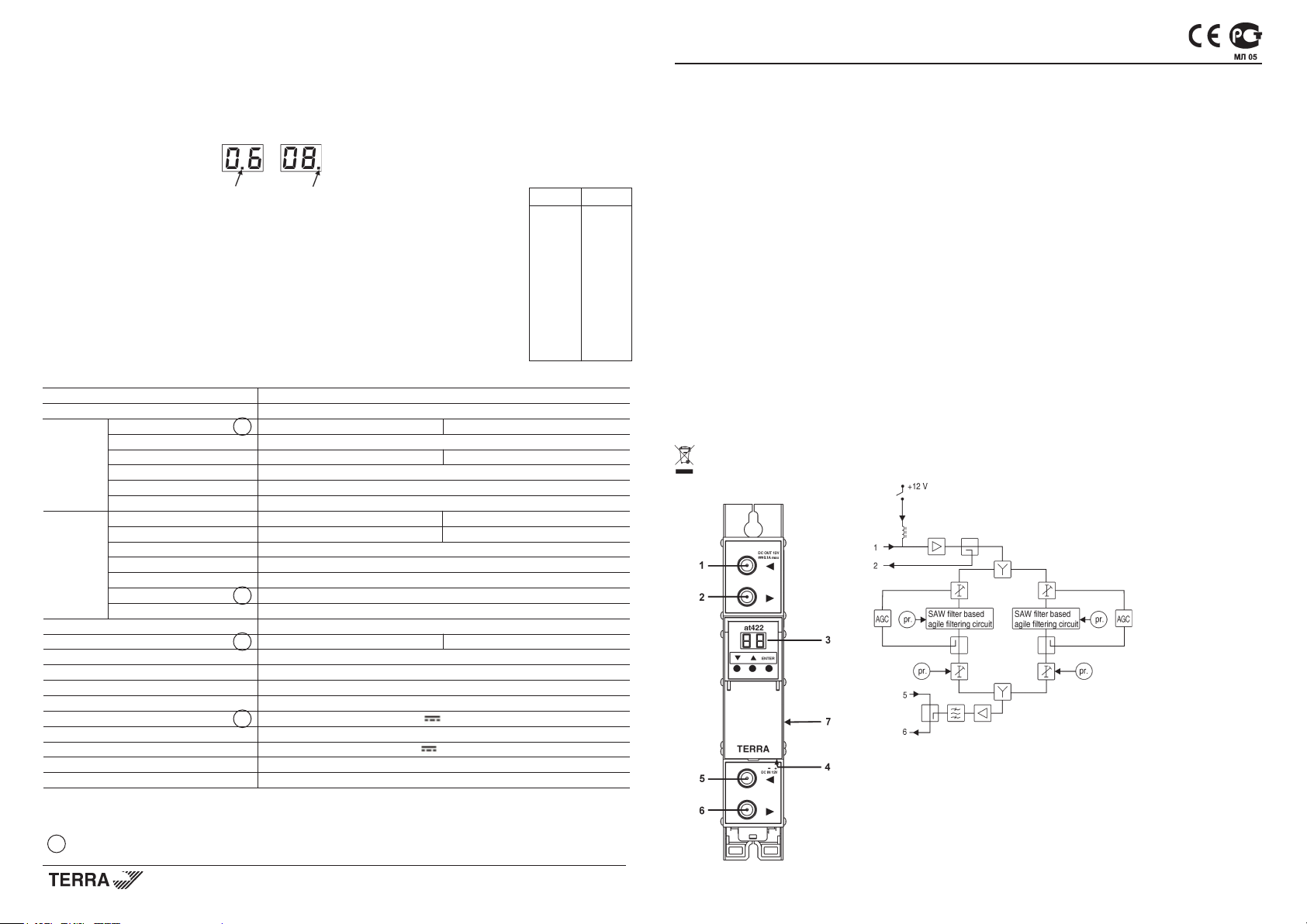
Twin TV channel amplier at422
Product description
The at422 twin TV channel amplier is intended to lter and equalize TV signals of VHFIII channels before distributing
in the network.
There are incorporated two fully independent TV ampliers in one unit and consist of: AGC (Automatic Gain Control) circuit,
SAW (Surface Acoustic Wave) based ultra high selective lter, IF (Intermediate Frequency) offset control circuit, adjustable
output attenuator and controllable +12 V DC feeding circuit for preamplier (Figure 1).
The amplier can be used as stand-alone unit as well as modular system powered from single power supply (Figure 3).
The amplier has been designed in accordance with standard EN 50083-5 class 2.
The amplier is intended for indoor use only.
RoHS compliant.
Safety instructions
Installation of the amplier must be done according EN 60728-11 and local safety standards.
The amplier is powered from power supply unit (PSU) +12 V. This voltage is not dangerous to life.
PSU +12 V must have a short circuit protection.
Any repairs must be done by qualied personnel.
Do not plug the PSU +12 V into the mains socket until all amplier's cables have been connected correctly. The mains
socket of PSU +12 V must be easily accessible.
To disconnect the amplier, disconnect the PSU +12 V from mains.
When amplier is disconnected, LED display does not glow.
Amplier shall not be exposed to dripping or splashing water and no objects lled with liquids, such as vases, shall be
placed on it.
Avoid placing amplier next to central heating components and in areas of high humidity.
No naked ame sources, such as lighted candles, should be placed on amplier.
If the amplier has been kept in cold conditions for a long time, keep it in a warm room no less than 2 hours before
plugging into the mains.
The ventilation should not be impeded by covering the ventilation openings with items, such as newspapers, table-cloths,
curtains.
Mount the amplier in vertical position.
From top, front and bottom of installed amplier must be as least 10 cm free space.
This product complies with the relevant clauses of the European Directive 2002/96/EC. The unit must be recycled or
discarded according to applicable local and national regulations.
External view
1 - ◄ - RF input, DC output +12 V switchable (F socket)
2 - ►- RF output (input signal loop-through) (F socket)
3 - two digit LED display
4 - +12 V powering input (screw terminal)
5 - ◄ - RF input (output signal loop-through) (F socket)
6 - ► - RF output (F socket)
7 - power distribution bus connector (under the cover)
Figure 1. External view and structure diagram
Page 2
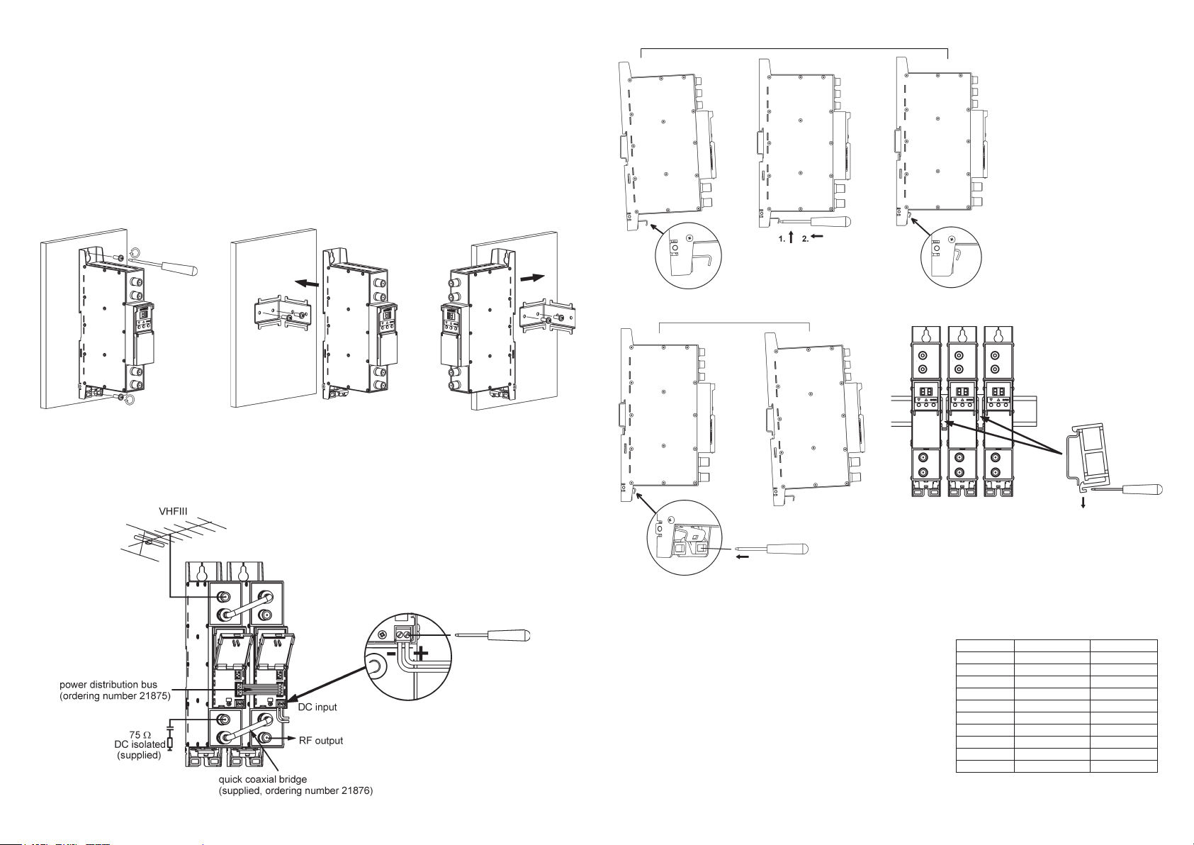
Installation instructions
Read the safety instruction rst.
DC power should be connected, after at422 mechanically placed into position (Figure 2, 4) and connected (Figure 3).
Menu settings are ready for user updates.
If RF IN connector (5) is not used, connect the 75Ω isolated load supplied (Figure 1).
If one of two ampliers is used only, switch off RF of unused one.
ATTENTION!
1. RF output is switched off as a default.
2. RF output level of the amplier should be set after half an hour of warm-up.
3. Set the difference of RF output levels less then 2 dB.
4. Do not use 75 Ω terminator without DC isolation.
MOUNTING
Mounting on a wall by screws Mounting on a bracket (supplied)
Perpendicular to the wall Parallel to the wall
Figure 2. Mounting of amplier
Mounting on DIN rail
Figure 4. Mounting to DIN rail
Table 3.
Connection of cables
Figure 3. Powering of amplier
Figure 6. Mounting or removing to/from
DIN rail of plastic spacers (supplied).
Figure 5. Mounting from DIN rail
Default settings
The ampliers are supplied with the following default settings:
Section 1, Section 2 Displayed Displayed
TV standard Au TV standard B
TV channel 06 (see table 1) 05 (see table 1)
Output attenuator (00-10) dB 00 00
RF output (on/oF) OF (RF off) OF (RF off)
Analog/ Digital (On/OF) 0F (Digital channel) 0F (Digital channel)
Offset (-8 8) 0 (see table 2) 0 (see table 2)
DC on RF input (0 /12) 0 0
TV standard (Au/B) AU B
Table 1.
Central freq. TV standard Au TV standard B
177.5 MHz
184.5 MHz
191.5 MHz
198.5 MHz
205.5 MHz
212.5 MHz
219.5 MHz
226.5 MHz
211.5 MHz
218.5 MHz
06 05
07 06
08 07
09 08
9A 09
10 10
1 1 1 1
12 12
90
91
 Loading...