

Page 1
Twin TV channel amplier at420
Product description
The at420 twin TV channel amplier is intended to lter and equalize TV signals of UHF channels before distributing in
the network.
There are incorporated two fully independent TV ampliers in one unit and consist of: AGC (Automatic Gain Control) circuit,
SAW (Surface Acoustic Wave) based ultra high selective lter, IF (Intermediate Frequency) offset control circuit, adjustable
output attenuator and controllable +12 V DC feeding circuit for preamplier (Figure 1).
The amplier can be used as stand-alone unit as well as modular system powered from single power supply (Figure 3).
The amplier has been designed in accordance with standard EN 50083-5 class 2.
The amplier is intended for indoor use only.
RoHS compliant.
Safety instructions
Installation of the amplier must be done according EN 60728-11 and local safety standards.
The amplier is powered from power supply unit (PSU) +12 V. This voltage is not dangerous to life.
PSU +12 V must have a short circuit protection.
Any repairs must be done by qualied personnel.
Do not plug the PSU +12 V into the mains socket until all amplier's cables have been connected correctly. The mains
socket of PSU +12 V must be easily accessible.
To disconnect the amplier, disconnect the PSU +12 V from mains.
When amplier is disconnected, LED display does not glow.
Amplier shall not be exposed to dripping or splashing water and no objects lled with liquids, such as vases, shall be
placed on it.
Avoid placing amplier next to central heating components and in areas of high humidity.
No naked ame sources, such as lighted candles, should be placed on amplier.
If the amplier has been kept in cold conditions for a long time, keep it in a warm room no less than 2 hours before
plugging into the mains.
The ventilation should not be impeded by covering the ventilation openings with items, such as newspapers, table-cloths, curtains.
Mount the amplier in vertical position.
From top, front and bottom of installed amplier must be as least 10 cm free space.
This product complies with the relevant clauses of the European Directive 2002/96/EC. The unit must be recycled or
discarded according to applicable local and national regulations.
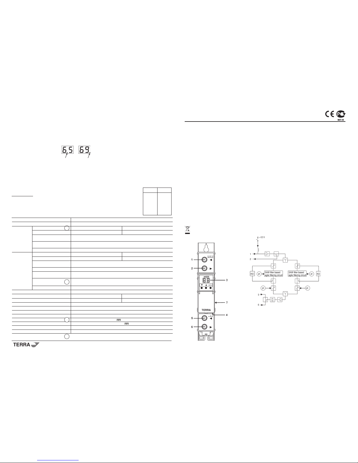
External view
1 - ◄ - RF input, DC output +12 V switchable (F socket)
2 - ►- RF output (input signal loop-through) (F socket)
3 - two digit LED display
4 - +12 V powering input (screw terminal)
5 - ◄ - RF input (output signal loop-through) (F socket)
6 - ► - RF output (F socket)
7 - power distribution bus connector (under the cover)
Figure 1. External view and structure diagram
Draugystes str. 22, LT-51256 Kaunas, Lithuania, tel.: +370 37 - 31 34 44, fax: +370 37 - 31 35 55
E-mail: terra@terraelectronics.com, http://www.terraelectronics.com
pr.
Таблица 1
Отображено Сдвиг
MHz
0 0
1 +0.25
2 +0.5
3 +0.75
4 +1.0
-4 -1.0
-3 -0.75
-2 -0.5
-1 -0.25
Изменение смещения
УПРАВЛЕНИЕ
Изменение установок
Усилитель имеет два режима работы:
1. нормальный: включается после включения в сеть;
ТВ канал (21-69) выбирается в нормальном режиме работы нажатием кнопок ▼ или ▲.
2. установок: включается одновременным нажатием кнопок ▼ и ▲ в течении 1 сек., выключается повторным
одновременным нажатием кнопок ▼ и ▲ в течении 1 сек.
Установка параметров для каждой секции производится по отдельности. Секция 1 или 2 выбирается в нормальном
режиме работы нажатием кнопки "Enter" (напр.: 6.5 - 1 секция, выходной канал 65; 69. - 2 секция, выходной канал 69),
смотрите рис. 7:
Рис. 7.
Положение светящейся точки показывает, которая секция выбрана.
Выбор нужного параметра осуществляется нажатием кнопки ▼.
Введите значения параметров нажимая кнопку ▲:
1. 00 10 - Выходной аттенюатор от 0 dB до -10 dB с шагом 1 dB
2. on/o F - РЧ выход включен/выключен
3. On/O F - Аналоговый / Цифровой (On для аналогового канала)
4. -4 4 - Смещение центральной частоты относительно фильтра (см. табл. 1)
5. 0 /12 - DC на входе РЧ
Если ТВ канал (21-69) был изменен, смещение частоты активной секции будет
установлено в положение 0 (см. табл. 1).
ПРИМЕЧАНИЕ! DC на входе РЧ (0 /12) может привести к повреждению устройств без
развязки по постоянному току.
Если в течении 1 мин. ни одна из кнопок не была нажата, усилитель переходит в дежурный
режим (- -). Для выхода из дежурного режима нажмите любую кнопку.
При выключении питания информация настройки сохраняется.
Технические характеристики
Таблица 2.
Секции 2
Частотный диапазон перестройки каналов 470-862 MHz (21-69 кан.)
РЧ вход режим аналоговый цифровой
уровень/импеданс 60-85 dBµV/75 Ω 50-80 dBµV/75 Ω
полоса частот распределения
47-862 MHz
РЧ сигнала
коэффициент передачи
0 ± 1.5 dB
входного ответвления
возвратные потери > 12 dB
РЧ выход уровень/импеданс, типичный 90 dBµV/75 Ω 85 dBµV/75 Ω
MER сигнала DTT - ≥36 dB (входной сигнал MER 38 dB)
полоса частот суммирования
47-2150 MHz
РЧ сигнала
проходной ток, напряжение 0.3 A, 24 V макс.
проходные потери
1.5/2.5 dB
суммирования РЧ Terr/SAT
пределы регулирования
0 ÷-10 dB с шагом 1 dB
выходного уровня
возвратные потери ≥ 10 dB
Коэффициент шума 8 dB
Селективность (соответст. стандарту PAL B/G), типич. 40 dB, ±1.25 MHz от границы полосы 8 MHz -
Селективность, типичная - 40 dB, ± 2 MHz от границы полосы 8 MHz
Смещение ± 1 MHz с шагом 0.25 MHz
Уровень помех сигналов ≤-60 dBc
Селективность зеркального канала ≥60 dB
Неравномерность в полосе канала ± 1.5 dB
Питание внешних устройств 12 V 0.1 A макс.
Напряжение питания / Потребляемый ток* 12 V ± 1 V / 0.45 A
Диапазон рабочих температур 0o ÷ + 50o C
Габариты/Вес (в упаковке) 198x107.5x36 mm /0.9 kg
pr.
pr.
* без внешней нагрузки по ПТ
переключается программным путем
pr.
Multichannel headend
Page 2
Installation instructions
Read the safety instruction rst.
DC power should be connected, after at420 mechanically placed into position (Figure 2, 4 and connected Figure 3).
Menu settings are ready for user updates.
If RF IN connector (5) is not used, connect the 75Ω isolated load supplied (Figure 3).
If one of two ampliers is used only, switch off RF of unused one.
If it is possible, set at420 RF channels as far as possible one from another.
ATTENTION!
1. RF output is switched off as a default.
2. RF output level of the amplier should be set after half an hour of warm-up.
3. Set the difference of RF output levels in at420 less then 2 dB.
4. Do not use 75 Ωterminator without DC isolation.
5. Recommendation for analog channels: the difference of RF input level should not exceed 5 dB for every second
channel pair (e.g. 21 and 23, 41 and 43, 61 and 63); 10 dB for every fth channel pair (e.g. 21 and 26, 41 and 46, 61 and 66).
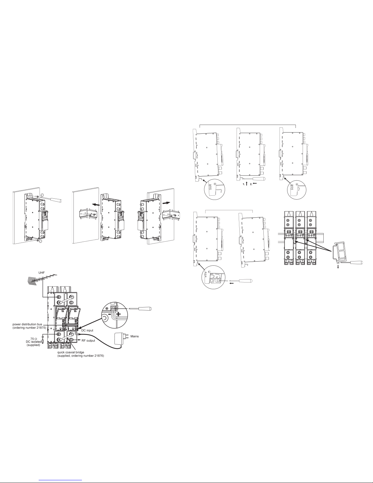
MOUNTING
Mounting on a wall by screws Mounting on a bracket (supplied)
Connection of cables
Perpendicular to the wall Parallel to the wall
Figure 2. Mounting of amplier
Figure 3. Powering of amplier
72
Крепление к планке''DIN rail''
Конфигурация изготовителя
Изготовителем, при выпуске усилителя, выставлены следующие величины параметров:
Секция 1, Секция 2 Отображение на индикаторе
UHF канал (21-69) 21
Выходной аттенюатор (00-10) dB 00
РЧ выход (on/oF) oF (RF выключен)
Аналоговый / Цифровой (On/OF) OF (Цифровой канал)
Смещение (-4 4) 0 (см. табл. 1)
DC на входе РЧ (0 /12) 0 (DC - напряжение постоянного тока)
Защита от несанкционированного доступа
Для защиты усилителя от несанкционированного доступа, необходимо дважды в течении ~0.5 сек. одновременно
нажать кнопки ▼ и ▲. Символ “LO” появится коротко. Для отключения защиты, необходимо повторить выше указанные
действия. Символ “UL” появится коротко. Символ “LO” появится на экране в случае, если управление усилителем
заблокировано.
Рис. 4. Крепление к планке ''DIN rail''
Рис. 5. Демонтаж с планки ''DIN rail''
Рис. 6. Крепление или демонтаж к
либо с ''DIN rail'' пластиковых вставок
(входят в комплект поставки).
Page 3

3
6
Mounting on DIN rail
Default settings
The ampliers are supplied with the following default settings:
Section 1, Section 2 Displayed
UHF channel (21-69) 21
Output attenuator (00-10) dB 00
RF output (on/oF) oF (RF off)
Analog/ Digital (On/OF) OF (Digital channel)
Offset (-4 4) 0 (see table 1)
DC on RF input (0 /12) 0
Locking the front panel controls
To lock keyboard LO or unlock keyboard UL, press buttons ▼ + ▲ simultaneously twice for 0.5 sec. "LO" will briey be
displayed. To revert to normal operation, repeat above procedure. "UL" will briey be displayed. The symbol "LO" appears,
if you try to change settings in locked mode.
Figure 4. Mounting to DIN rail
Figure 5. Mounting from DIN rail
Figure 6. Mounting or removing to/from
DIN rail of plastic spacers (supplied).
Инструкция по инсталляции
Перед началом работы прочтите инструкцию по эксплуатации и электробезопасности.
Напряжение питания должно быть подключено после того, как at420 будет установлен в соответствующую
позицию (Рис. 2, 4 и подключен Рис. 3). После этого, устанавливается меню нормального режима работы и возможна
настройка параметров потребителем.
Если вход RF IN (5) не используется, к нему необходимо подключить изолированную по постоянному току нагрузку
75 Ω, входящую в комплект поставки (см. Рис. 3).
Если используется только один усилитель, выключите РЧ неиспользуемого усилителя.
Если есть возможность, установите at420 РЧ каналы как можно дальше друг от друга.
ВНИМАНИЕ!
1. Изготовителем, при выпуске модуля, РЧ выход выключен.
2. Время установления уровня РЧ сигнала усилителя 0.5 час.
3. Разница между уровнями сигналов на выходе соответствующих каналов должна быть не более ± 2 dB.
4. Не используйте нагрузки 75 Ωбез изоляции по постоянному току.
5. Рекоммендации для аналоговых каналов: разница входного РЧ уровня не должна превышать 5 dB для каждого
второго канала (напр. 21 и 23, 41 и 43, 61 и 63); 10 dB для каждого пятого канала (напр. 21 и 26, 41 и 46, 61 и 66).
Крепление
Крепление к стене саморезами Крепление на угольнике (входит в комплект поставки)
Подключение кабелей
Перпендикулярно к стене Параллельно к стене
Рис. 2. Крепление усилителя
Рис. 3. Питание усилителя
Page 4

5
4
pr.pr.
pr.
pr.
Sections 2
Tuning range of channels 470-862 MHz (21-69 ch.)
RF input TV standard analog digital
level/impedance 60-85 dBµV/75 Ω 50-80 dBµV/75 Ω
frequency range of RF distribution 47-862 MHz
loop through gain 0 ± 1.5 dB
return loss >12 dB
RF output level, typical 90 dBµV 85 dBµV
MER of DTT signal - ≥36 dB (input signal MER 38 dB)
frequency range of RF combining 47-2150 MHz
DC pass through, max. 0.3 A 24 V
combining through loss Terr/SAT 1.5/2.5 dB
level adjustment range 0 ÷-10 dB by 1 dB step
return loss ≥10 dB
Noise figure 8 dB
Selectivity (referring to PAL B/G standard), typical 40 dB, ±1.25 MHz 8 MHz from bandwidth border -
Selectivity, typical - 40 dB, ± 2 MHz from 8 MHz bandwidth border
Offset ± 1 MHz by 0.25 MHz step
Spurious signals level ≤-60 dBc
Mirror channel selectivity ≥ 60 dB
Flatness of channel bandwidth, typical ± 1.5 dB
DC feeding for external 12 V 0.1 A max.
Supply voltage 12 ± 1 V
Current consumption* 0.45 A
Operating temperature range 0o ÷+50o C
Dimensions/Weight (packed) 198x107.5x36 mm/0.9 kg
* without external DC loading
pr.
software control
Table 1
Displayed Shift
MHz
0 0
1 +0.25
2 +0.5
3 +0.75
4 +1.0
-4 -1.0
-3 -0.75
-2 -0.5
-1 -0.25
Offset tunning
OPERATING
Settings menu
The amplier has two modes of operating:
1. Normal mode: sets after switch on;
RF channel (21-69) can be set in normal mode by pressing buttons ▼ or ▲.
2. Setting mode: to enter the setting mode press and hold ▼ and ▲ buttons simultaneously for 1 second, to exit mode
press and hold ▼ and ▲ buttons simultaneously for 1 second again.
Menu settings of each section should be set individually. Section 1 or 2 can be selected by pressing button “Enter” (for
example: 6.5 - 1 section, output channel 65; 69. - 2 section, output channel 69), see Figure 7:
Figure 7.
Position of glowing dot means which section is activated.
Select necessary to change parameter by pressing button ▼.
Enter necessary parameter values by pressing ▲ button:
1. 00 10 - Output attenuator 0 dB to -10 dB by 1 dB step
2. on/o F - RF output on/off
3. On/O F - Analog/ Digital (On for analog channel)
4. -4 4 - Offset of a central frequency in respect to lter (see table 1)
5. 0 /12 - DC on RF input
If RF channel (21-69) is changed, frequency offset of current section will be reseted.
NOTE! DC on RF input (0 /12) can be dangerous for some devices.
If no action is taken for 1 minute, sleep mode (- -) is activated. To leave sleep mode press any button.
The last selected parameters will remain in memory if the power is interrupted.
Technical specications
Table 2.
Сдвоенный усилитель ТВ каналов at420
Назначение изделия
Сдвоенный усилитель сигналов ТВ каналов at420 предназначен для фильтрации и выравнивания UHF каналов
перед распределением в сети.
Два независимые ТВ усилителя встроенные в один модуль состоят из: схемы АРУ (Автоматическая Регулировка
Усиления), ПАВ (Поверхностная Акустическая Волна) фильтра с сверхвысокой селективностью, цепи управления смещения
ПЧ (Промежуточной Частоты), регулируемого выходного аттенюатора и +12 V цепи питания для предусилителя (Рис. 1).
Усилитель может быть использован в качестве самостоятельного блока, а также как модульная система, питаемая
от одного источника питания (Рис. 3).
Усилитель соответствует требованиям стандарта EN50083-5 класс 2.
Усилитель предназначен работать в закрытом помещении.
Соответствует RoHS.
Инструкция по электробезопасности
Инсталляция усилителя должна быть проведена в соответствии с требованиями стандарта EN 60728-11 и местных
стандартов электробезопасности.
Усилитель работает от источника питания +12 V. Напряжение не представляет опасность для жизни.
Источник питания +12 V должен иметь защиту от короткого замыкания.
Ремонтировать усилитель может только квалифицированный персонал.
Не подключайте источника питания +12 V в сеть, пока не подключенны все соединения модулей.
Розетка источника питания +12 V должна быть легко доступна.
Источник питания +12 V от сети отключается с помощью вилки питания.
Когда усилитель отключен от питания, двухразрядный индикатор не светит.
Не устанавливайте усилитель в местах где есть возможность попадания брызг или капель воды.
Не ставьте сосудов (напр. ваз) с водой или другими жидкостями вблизи усилителя, чтобы избежать попадания
жидкостей внутрь усилителя.
Не устанавливайте усилитель вблизи приборов отопления, а также в помещениях повышенной влажности.
На усилителе не должно быть источников открытого пламени, напр. таких как свеча.
После длительного хранения усилителя при низкой температуре, необходимо перед включением выдержать его
в теплом помещении не менее двух часов.
Не закрывайте вентиляционные отверстия усилителя посторонними предметами, напр. газетами, шторами;
При инсталляции крепите усилитель в вертикальном положении.
Сверху, cпереди и cнизу установленного усилителя должно быть не менее 10 см свободного пространства.
Данный продукт соответствует требованиям Европейской Директивы 2002/96/EC. Устройство должно быть
переработано или утилизировано в соответствии с местными и региональными правилами.
Внешний вид
1 - ◄ - РЧ вход, DC выход +12 V переключаемый (F разъем)
2 - ►- РЧ выход (для проходного суммирования по РЧ) (F разъем)
3 - двухразрядный индикатор
4 - напряжения питания +12 V (винтовой разъем)
5 - ◄ - РЧ вход (для проходного суммирования по РЧ) (F разъем)
6 - ► - РЧ выход (F разъем)
7 - разъем шины питания (под крышкой)
Рис.1. Внешний вид усилителя и диаграмма
Многоканальное головное оборудование
 Loading...