

Page 1
SOA
SOA
Element SOA
SOA
SOA
Page 2

Page 3
1. Nigdy nie używaj urządzenia, jeżeli jest ono w jakikolwiek sposób uszkodzone.
2. Przed podłączeniem urządzenia sprawdź, czy napięcie podane na tabliczce znamionowej
zgadza się z napięciem w domowej instalacji elektrycznej.
3. Regularnie sprawdzaj, czy przewód zasilający nie uległ uszkodzeniu i czy użytkowanie
jest bezpieczne.
4. Przewód zasilający nie podlega naprawie. Uszkodzony przewód powinien zostać wymieniony u Producenta
lub w specjalistycznym zakładzie naprawczym.
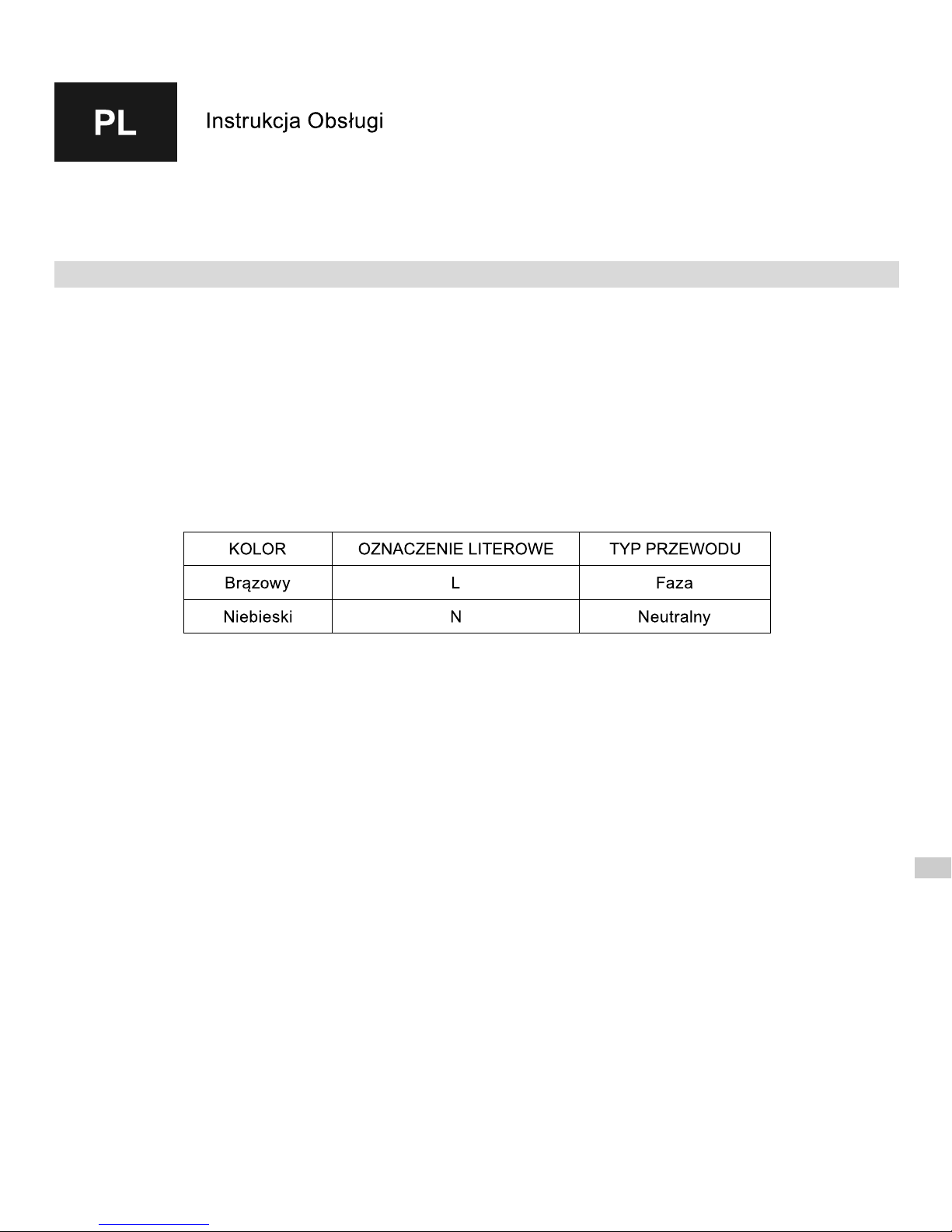
W przypadku wersji bez wtyczki (np. montaż bezpośrednio do puszki przyłączeniowej) oznaczenia kolorystyczne
przewodów są następujące:
Nasze wyroby zostały zaprojektowane i wyprodukowane tak, aby spełniały wszelkie wymagania jakości,
funkcjonalności i estetyki. Gratulujemy udanego zakupu i życzymy dużo zadowolenia przy użytkowaniu
nowego urządzenia.
5. Grzałka przeznaczona jest do pracy w cieczy. Dopuszcza się pracę grzałki na wolnym powietrzu przez okres
nie dłuższy niż 5 sekund. Nie dotykaj elementów metalowych – grozi oparzeniem. Nie pozwalaj, aby przewód
stykał się z rozgrzanym elementem grzejnym.
6. Podczas montażu urządzenie nie może znajdować się pod napięciem. Wyjmij wtyczkę z gniazda zasilającego
lub odłącz przewód od sieci zasilającej.
7. Nie otwieraj obudowy.
8. Nie dopuszczaj do zalania obudowy sterownika.
10. Stojąc w wannie, brodziku lub boso na mokrej podłodze nie dotykaj urządzenia elektrycznego.
11. Moc grzałki nie może przekraczać 100% mocy grzejnika dla parametrów 75/65/20°C.
12. Ciśnienie w grzejniku nie może przekroczyć wartości podanej przez producenta grzejnika, ani wartości 10 atm
dla grzałki. Przekroczenie dopuszczalnych ciśnień może doprowadzić do uszkodzenia grzejnika lub grzałki
i spowodować zagrożenia dla zdrowia, życia lub mienia.
13. W grzejniku elektrycznym należy pozostawić poduszkę powietrzną o odpowiedniej objętości (patrz -> Instalacja),
14. W grzejniku wodno-elektrycznym (podłączonym do sieci C.O.) przed włączeniem grzałki i podczas jej pracy
należy jeden z zaworów pozostawić otwarty w celu umożliwienia wypchnięcia nadwyżki wody spowodowanej jej
rozszerzalnością cieplną. Pozostawienie obu zaworów zamkniętych spowoduje nadmierny wzrost ciśnienia
i może uszkodzić grzałkę lub grzejnik (patrz -> „Grzejnik wodno-elektryczny / Instalacja”)
15. Urządzenie przeznaczone jest do użytku domowego.
16. Urządzenie nie jest przeznaczone do użytku przez dzieci oraz osoby o ograniczonej sprawności umysłowej
lub nie posiadające koniecznej wiedzy lub doświadczenia w zakresie obsługi podobnego sprzętu.
W takim przypadku konieczny jest nadzór lub odpowiednie przeszkolenie przez osoby odpowiedzialne
za ich bezpieczeństwo.
ZASADY BEZPIECZNEGO UŻYTKOWANIA
Uważnie przeczytaj poniższą instrukcję i zapoznaj się z ilustracjami.
Page 4
PRZEZNACZENIE URZĄDZENIA
Grzałki produkcji są elektrycznymi urządzeniami grzewczymi i służą do instalowania w grzejnikach przeznaczonych
do ogrzewania pomieszczeń lub suszenia ręczników i ubrań. Grzałka może być zainstalowana zarówno w grzejniku
podłączonym do instalacji C.O., pracując poza sezonem grzewczym, jak i w oddzielnym grzejniku elektrycznym.
Grzałki przeznaczone są wyłącznie do pracy w zbiornikach nie otwartych do atmosfery.
Klasa II
Page 5
GRZEJNIK ELEKTRYCZNY
INSTALACJA GRZAŁKI
1. Grzejnik zasilany wyłącznie grzałką elektryczną, nie podłączony do instalacji C.O.
2. Czynnikiem grzewczym może być woda, woda z dodatkiem środka antyzamarzaniowego lub odpowiedni olej -
warunkiem możliwości zainstalowania oraz poprawnej eksploatacji jest spełnienie wymogów producenta grzejnika
i grzałki.
3. Zalanie grzejnika nadmierną ilością cieczy prowadzi do przekroczenia dopuszczalnego ciśnienia i uszkodzenia
grzejnika lub grzałki. Przy samodzielnym napełnianiu należy postępować ściśle wg podanej poniżej instrukcji
napełniania grzejnika.
4. Inne metody prawidłowego zalewania grzejnika można znaleźć na stronie www.termaheat.pl. Nie należy zalewać
grzejnika czynnikiem grzewczym o temperaturze wyższej niż 65°C.
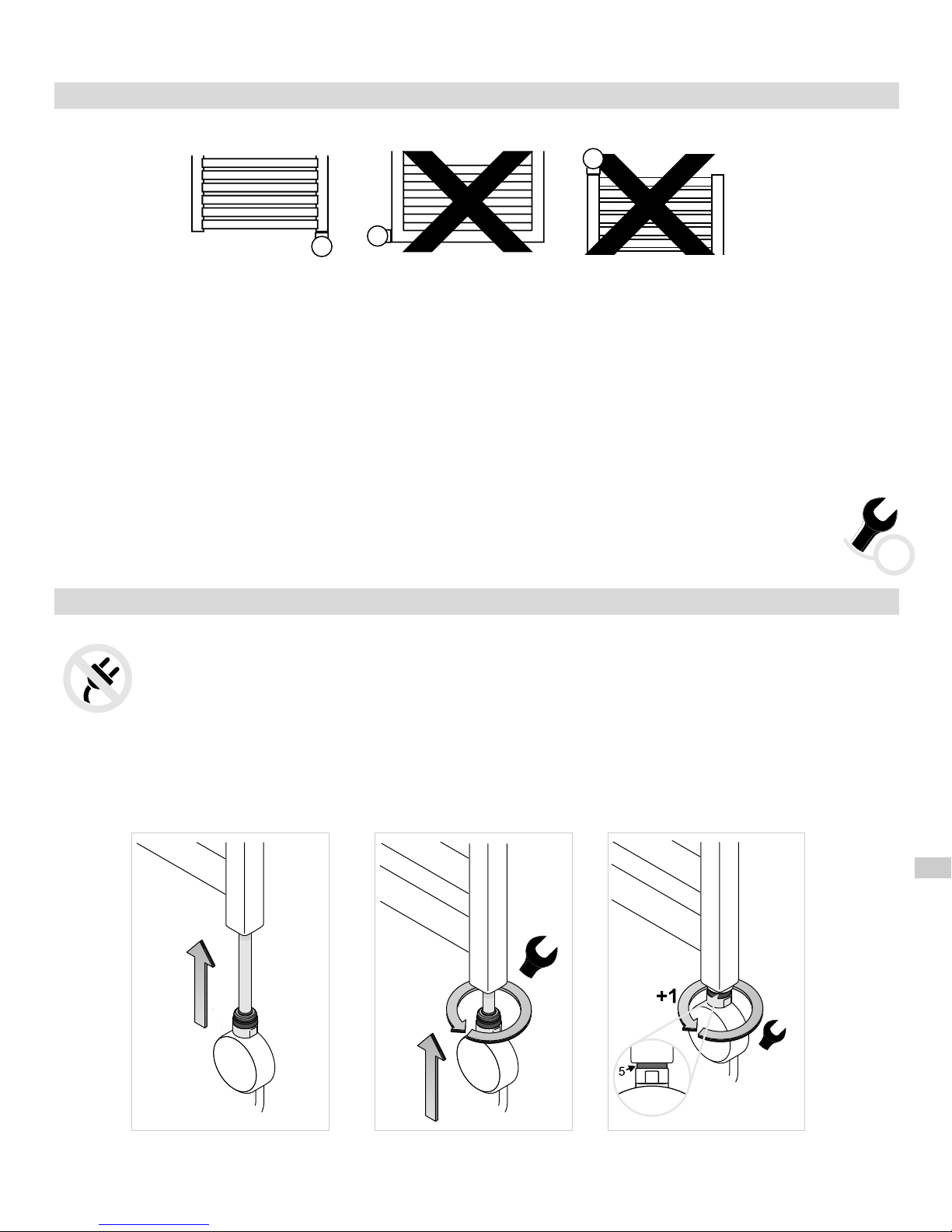
5. Grzałki nie należy montować elementem grzejnym skierowanym w dół.
6. Grzałki nie wolno wkręcać ani wykręcać trzymając za obudowę. Używaj wyłącznie klucza montażowego!
1. Wsuń element grzejny (1) do otworu gwintowanego u dołu kolektora grzejnika.
2. Dokręć głowicę grzałki przy użyciu klucza płaskiego 22.
3. Specjalna uszczelka (5) zapewnia szczelność połączenia oraz pozwala na wykonanie 1 dodatkowego obrotu
grzałką i właściwe ustawienie frontu grzałki.
UWAGA!
gniazda zasilającego.
UWAGA! Zachowaj ostrożność w czasie całego procesu napełniania grzejnika, aby uniknąć poparzenia
gorącym czynnikiem!
Podczas montażu urządzenie nie może znajdować się pod napięciem. Wyjmij wtyczkę, z
Narzędzia potrzebne do instalacji grzałki
– klucz płaski rozmiar 22
22
Page 6
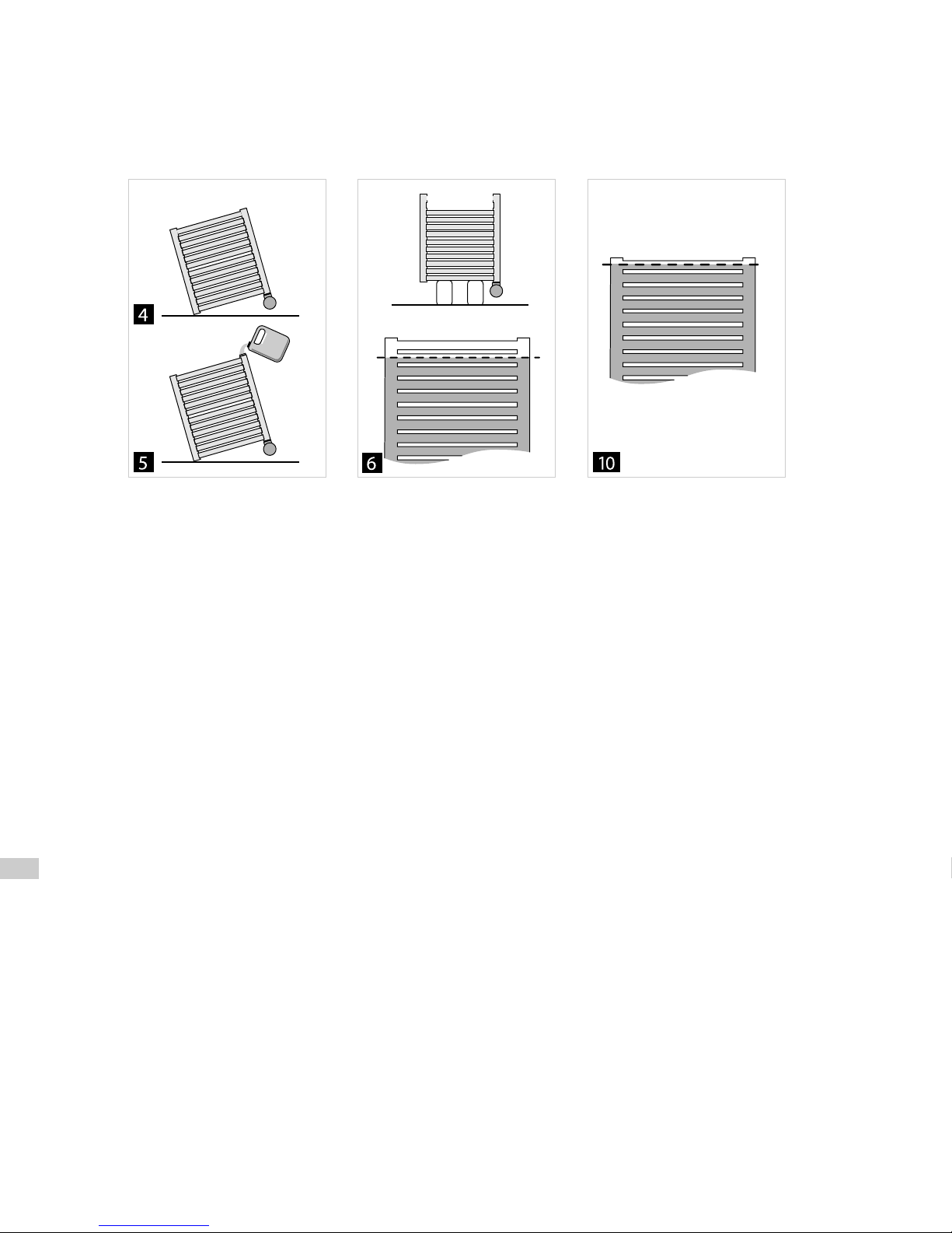
4. Ustaw grzejnik lekko ukośnie, tak, aby otwór wlewowy znajdował się w najwyższym punkcie.
Grzejnik nie może w żadnym momencie opierać się na sterowniku grzałki, ani na elementach złącza!
5. Napełnij grzejnik czynnikiem grzewczym.
6. Wyprostuj grzejnik i skontroluj poziom cieczy.
7. Upewnij się, że połączenie grzałka – grzejnik jest szczelne.
8. Podłącz urządzenie do gniazda zasilającego i włącz grzałkę (górny otwór pozostaje otwarty!).
8.1. Do zalania grzejnika można użyć gorącego czynnika o temperaturze nie wyższej niż 65 C. W takim
przypadku zalej grzejnik w całości, ustaw go prosto i włącz grzałkę.
9. Włącz grzałkę na maksymalnej nastawie i obserwuj podnoszący się poziom czynnika grzewczego – nadmiar
czynnika może się przelewać przez górny otwór – usuń wyciekający czynnik, aby nie dopuścić do zalania
sterownika grzałki.
10. Kiedy czynnik grzewczy przestanie zwiększać swoją objętość odczekaj jeszcze 5 minut i wyłącz grzałkę, odłącz
urządzenie od gniazda/sieci zasilającej.
11. Nie czekając, aż grzejnik ostygnie, zdejmij go ostrożnie i odlej niewielką ilość czynnika – do poziomu połowy
ostatniej rurki.
12. Zamknij górny otwór przeznaczonym do tego korkiem i zamocuj grzejnik ponownie na ścianie.
13. Podłącz grzałkę do gniazda zasilającego / do instalacji. Urządzenie jest gotowe do pracy.
°
Page 7
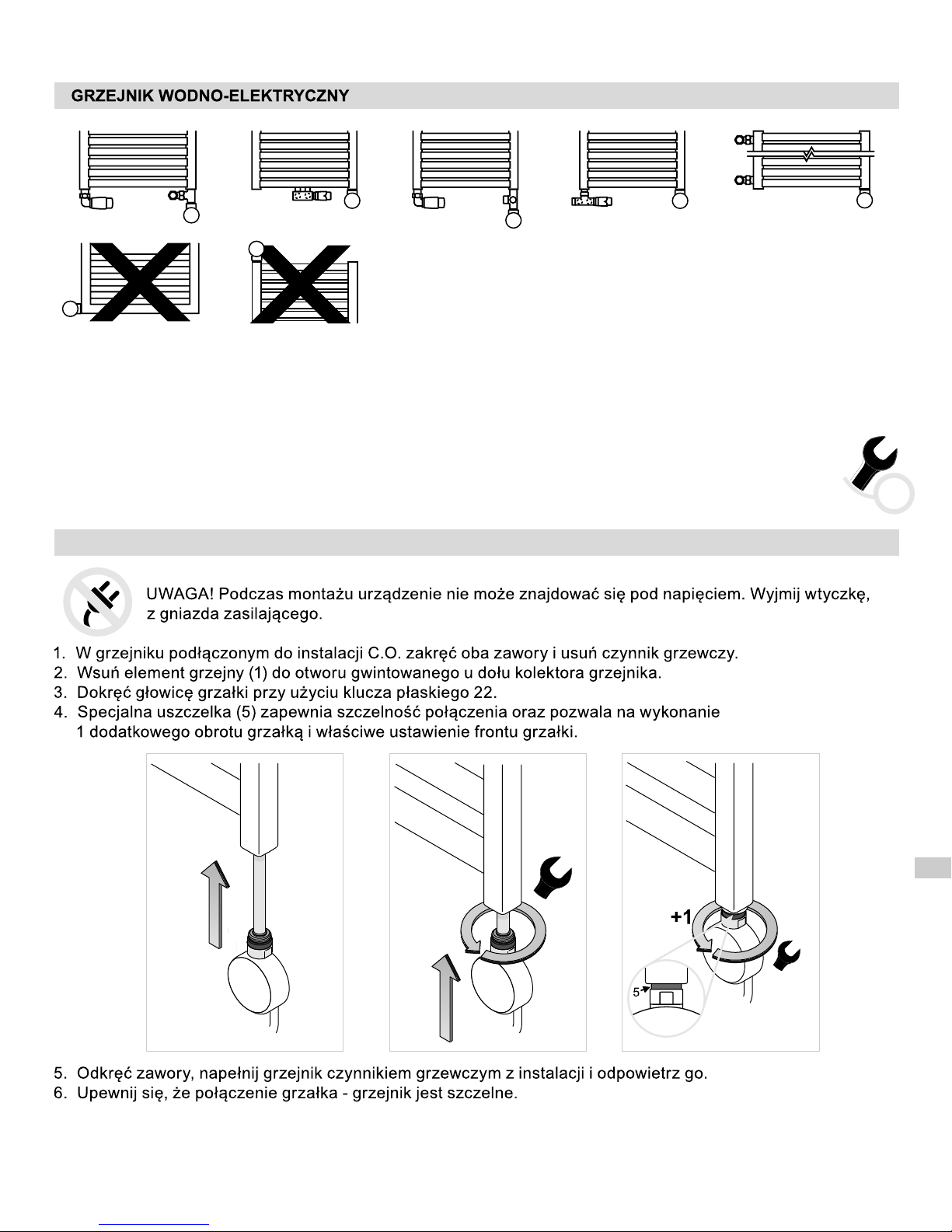
1. Grzejnik podłączony do sieci C.O., w którym dodatkowo montujemy grzałkę elektryczną.
2. Instalacja C.O. musi być wyposażona w zawory umożliwiające odcięcie grzejnika.
3. Zaleca się odpowietrzenie grzejnika po każdej dłuższej przerwie w użytkowaniu.
4. Grzałki nie należy montować elementem grzejnym skierowanym w dół.
INSTALACJA GRZAŁKI
Narzędzia potrzebne do instalacji grzałki
– klucz płaski rozmiar 22
22
Page 8
Page 9
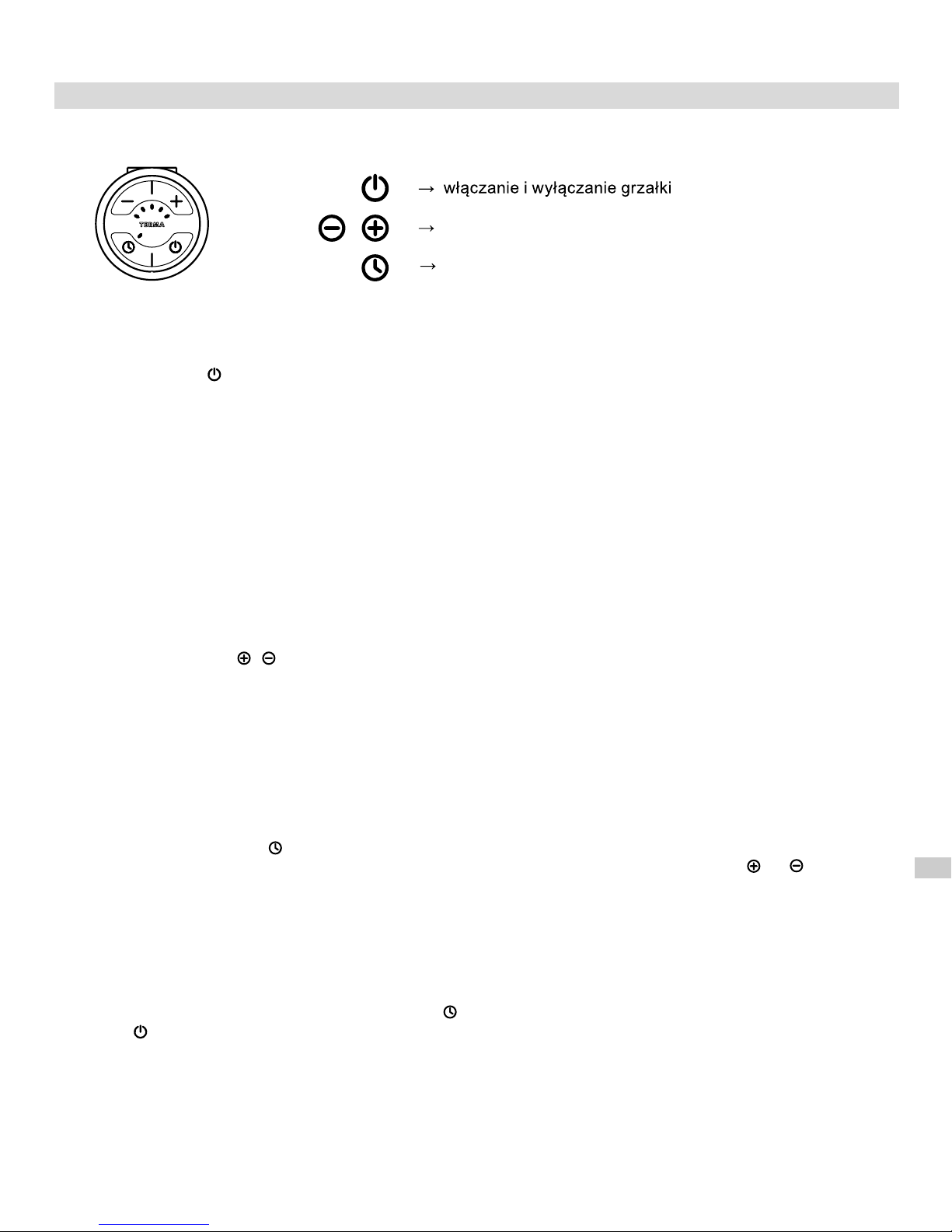
ustawienie mocy grzania
włączenie suszarki
Naciśnięcie klawisza uruchamia grzałkę, która rozgrzewa grzejnik okresowo włączając się oraz wyłączając
i kontynuuje pracę ze średnią mocą na poziomie ustawionym przez użytkownika w zakresie 30-100% mocy
znamionowej urządzenia.
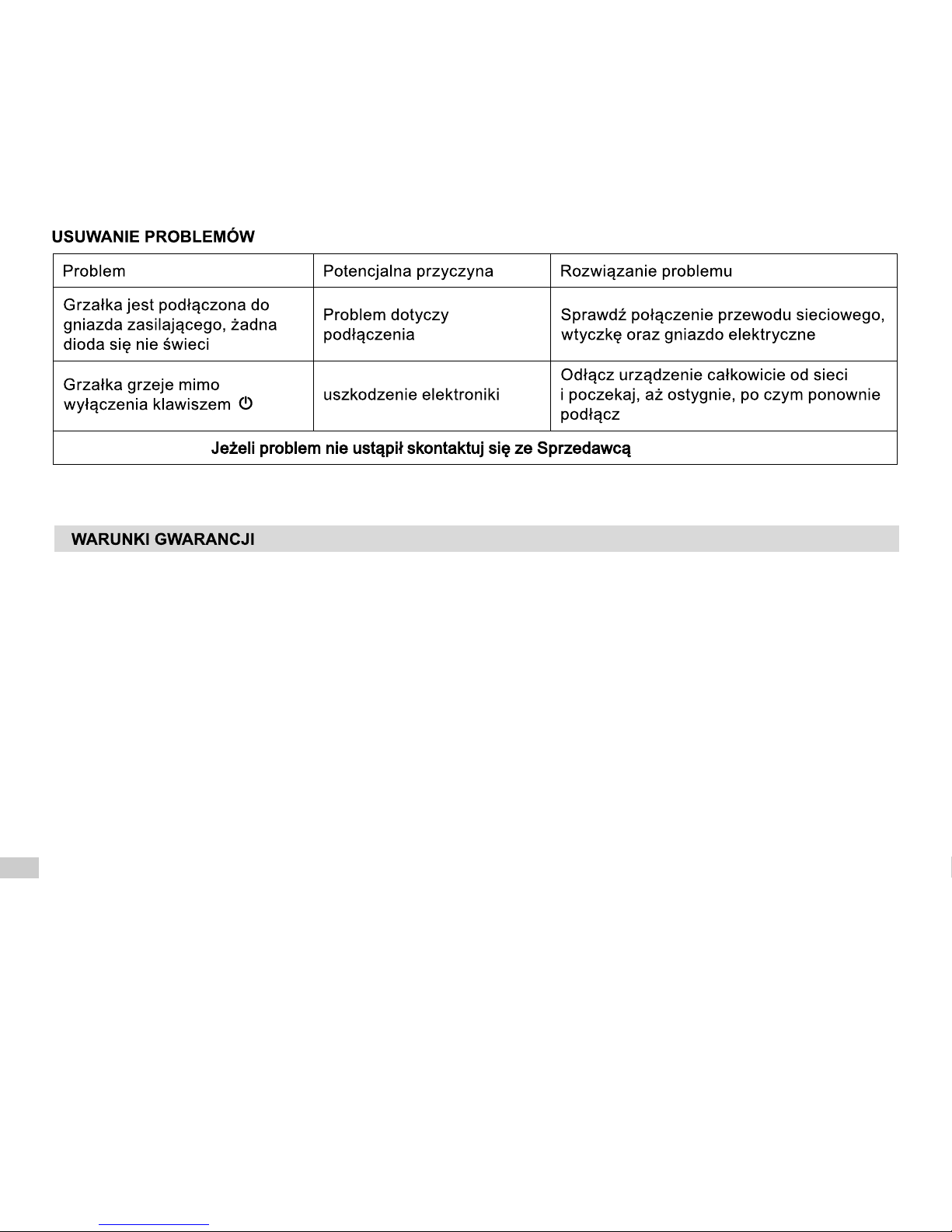
Konstrukcja grzałki (element grzejny PTC) chroni przed poparzeniem, samoczynnie ograniczając temperaturę
grzejnika do 60°C, niezależnie od aktualnej nastawy (pod warunkiem, że moc elementu grzejnego została
prawidłowo dobrana do mocy grzejnika).
Konstrukcja grzałki, jak również właściwości fizyczne czynnika grzewczego powodują, że dolne rurki grzejnika
(w szczególności ostatnie dwie) mogą mieć niższą temperaturę od pozostałej części – takie zjawisko jest
całkowicie normalne.
Aby uzyskać pożądany komfort cieplny pomieszczenia należy ustawić właściwy poziom mocy
grzania grzałki (klawisze i ).
Możliwe jest ustawienie jednego z pięciu poziomów mocy: 30 - 40 - 60 - 80 - 100% mocy znamionowej.
Wybranie kolejnego, wyższego zakresu pracy powoduje zapalenie się kolejnej diody.
Funkcja TIMER pozwala zaprogramować urządzenie, tak aby przez 2 godziny grzało z inną mocą, np. w celu
wysuszenia ręcznika. Po upływie tego czasu grzałka samoczynnie wraca do stanu pracy sprzed aktywacji
funkcji.
TIMER włącza się klawiszem (również, jeśli grzałka jest wyłączona). Urządzenie rozpocznie pracę
z aktualnie ustawioną mocą. Nastawę tę można w każdej chwili dowolnie zmienić klawiszami lub .
Jeśli przed uruchomieniem timera grzałka była wyłączona, to po zakończeniu suszenia urządzenie wyłączy
się samoczynnie.
Jeżeli przed uruchomieniem suszarki grzałka była włączona np. na nastawie 2, a po włączeniu timera nastawa
została ręcznie zmieniona np. na 4, to po 2 godzinach grzałka powróci do nastawy 2.
Uwaga: jeżeli grzałka jest włączona, a po naciśnięciu klawisza TIMER nastawa nie zostanie zmodyfikowana,
to po upływie 2 godzin nic się nie zmieni. Grzałka nadal będzie pracowała na bieżącej nastawie.
Aby przerwać pracę TIMER'a należy wcisnąć klawisz . Także wyłączenie i ponowne włączenie grzałki
klawiszem deaktywuje funkcję.
USTAWIENIE MOCY GRZANIA
FUNKCJA TIMER
FUNKCJE I OBSŁUGA URZĄDZENIA (model SOA)
Page 10
FUNKCJA ANTI-FREEZE (ochrona przeciwzamarzaniowa)
Jeżeli grzałka jest wyłączona, a temperatura w okolicy czujnika temperatury spadnie poniżej progu 6°C nastąpi
automatyczne włączenie grzałki, aby nie dopuścić do zamarznięcia czynnika grzewczego wewnątrz grzejnika.
Grzałka sygnalizuje wykrycie zbyt niskiej temperatury migając środkową diodą.
1. Przedmiotem gwarancji jest grzałka elektryczna produkcji Terma Sp. z o.o. Nazwa modelu oraz
własności wyszególnione zostały na opakowaniu
2. Odbierając urządzenie Klient potwierdza pełnowartościowość produktu. W razie stwierdzenia jakichkolwiek wad
należy poinformować o nich Sprzedawcę – w przeciwnym wypadku przyjmuje się, że Sprzedawca wydał produkt
bez wad. Dotyczy to w szczególności jakości powierzchni obudowy sterownika.
3. Okres gwarancji wynosi 24 miesiące od daty zakupu, ale nie dłużej niż 36 m-cy od daty produkcji.
4. Podstawą roszczeń gwarancyjnych jest karta gwarancyjna wraz z dowodem zakupu. Nie okazanie
któregokolwiek z w/w dokumentów upoważnia producenta do oddalenia roszczenia gwarancyjnego.
5. Gwarancją nie są objęte uszkodzenia powstałe:
– na skutek nieprawidłowego (niezgodnego z instrukcją) montażu, użytkowania lub demontażu,
– w związku z zastosowaniem elementu grzejnego w sposób niezgodny z jego przeznaczeniem,
– na skutek ingerencji w urządzenie osób nieupoważnionych,
– powstałe z winy Klienta po odbiorze od Sprzedającego.
6. Instalacja grzewcza powinna być wyposażona w zawory odcinające, umożliwiające demontaż grzejnika
lub grzałki bez opróżniania całej instalacji z czynnika grzewczego. Problemy lub koszty powstałe na skutek
braku takich zaworów w instalacji nie obciążają Terma.
7. Załączona instrukcja obsługi produktu jest integralną częścią gwarancji. Prosimy zatem o dokładne zapoznanie
się z jej treścią przed przystąpieniem do użytkowania.
8. Producent zobowiązuje się do usunięcia usterki w terminie 14 dni roboczych od daty dostarczenia wadliwego
urządzenia do siedziby producenta.
9. Jeżeli naprawa urządzenia okaże się niemożliwa, producent zobowiązuje się do dostarczenia nowego, sprawnie
działającego egzemplarza o tych samych parametrach.
Page 11
Our products have been designed and manufactured in such a way to ensure that all the quality, functionality and
aesthetic requirements are met. We would like to congratulate you on this great purchase and wish You a pleasant
use.
SAFETY REGULATIONS
Please read the below instructions thoroughly and study the images carefully.
1. Never use the device that is damaged in any way.
2. Please check if the tally voltage equals the voltage of the electric installation in your home prior to connecting
the device.
3. Please check regularly if the power wire is not damaged and if the device can be used in a safe manner.
4. Power wire is not subject to repair. Damaged power wire should be replaced at the Manufacturer's or specialised
service centre.
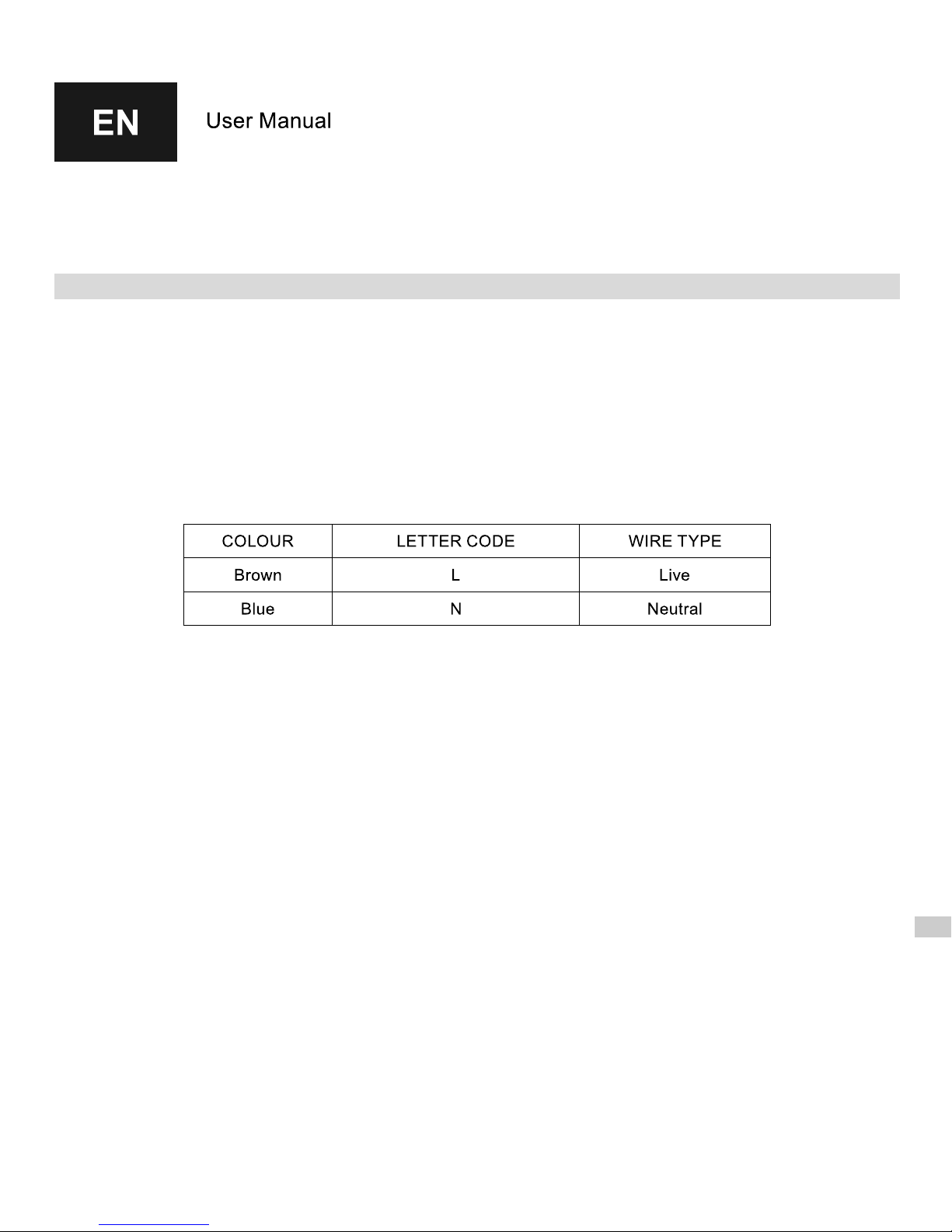
For devices without the plug (ie. connected directly to installation), please see below colour codes for each wire:
5. Heating element is intended to work in a liquid medium environment. It is advised not to turn the device on in dry
conditions for longer than 5 seconds.
Do not touch metal parts – burning risk. Always make sure that the wire does not touch the heating element that
is hot.
6. The device must not be connected while being installed. Unplug the device or disconnect the power wire from
electrical circuit.
7. Do not open the enclusure.
8. Do not allow for the enclosure of the control head to get flooded or splashed with water or any other liquid.
9. Do not touch the electric device while standing in the bathtub, shower or barefoot on the floor.
10. Heating element's electric output cannot exceed 100% heating output of the radiator for the following
parameters: 75/65/20°C.
11. Pressure inside the radiator must not exceed the pressure value recommended by the radiator's manufacturer or
the pressure of 10 atmospheres for the heating element. Exceeding of recommended pressures may result in
the radiator or heating element damage and cause possible threat for health, life and property.
12. An air pillow of the correct parameters should always be allowed for inside an electric radiator (see →
Installation).
13. In case of a dual fuel radiator (connected to the central heating system) one of the valves should be left open
prior to turning the heating element on and during its operation in order for the excess water created due to its
heat expansiveness to be pushed out. Leaving both valves closed will result in excessive pressure growth which
may lead to damaging of the heating element or radiator (see → “Dual fuel radiator / Installation”)
14. The device is intended for home use.
15. The device is not intended for use by children, persons with limited mental capacity or those who do not have
sufficient knowledge or experience required for handling this type of equipment. In such cases, control or
training by persons responsible for safety of the above mentioned is required.
Page 12
INTENDED USE OF DEVICE
Terma heating elements and control heads are electric heating devices and are intended for installation and use in
radiators used for heating interior spaces or drying towels or clothes. Heating element and control head can be
installed in a radiator connected to the central heating system for use during the heating season as well as in an
individual electric radiator.
Heating elements are designed to operate in containers which are not open to atmosphere.
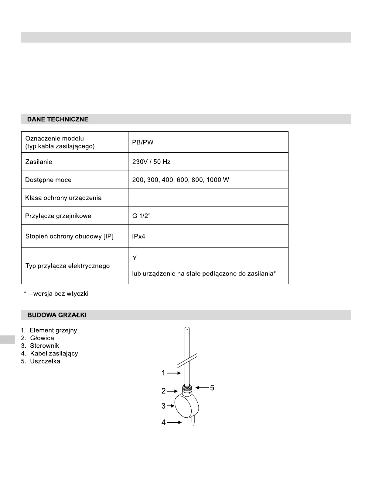
TECHNICAL INFORMATION
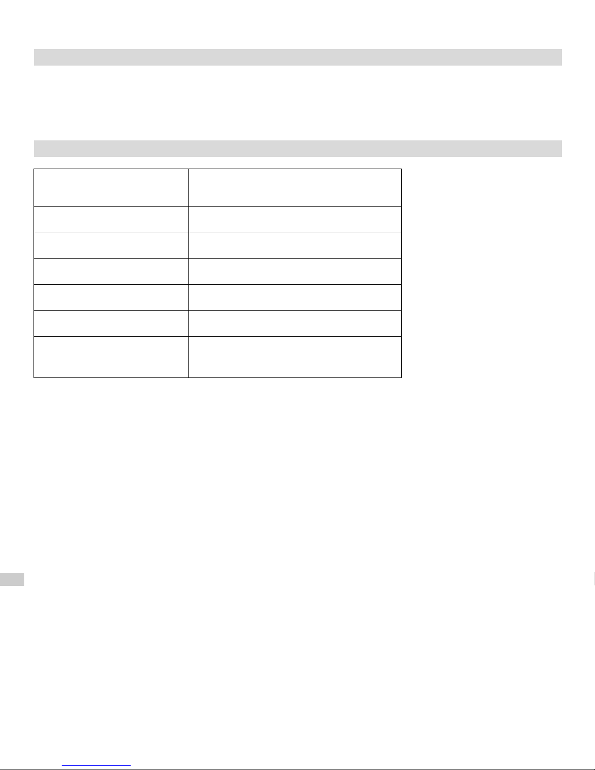
Model code (power wire type) PB / PW
Electric power supply 230 V / 50 Hz
Heating output available 200, 300, 400, 600, 800, 1000 W
Device protection class Class II
Radiator connection G 1/2"
Enclosure protection rating [IP] IPx4
Electric connection type Y
power supply (for connections with no plug)
or device permanently connected to
Page 13
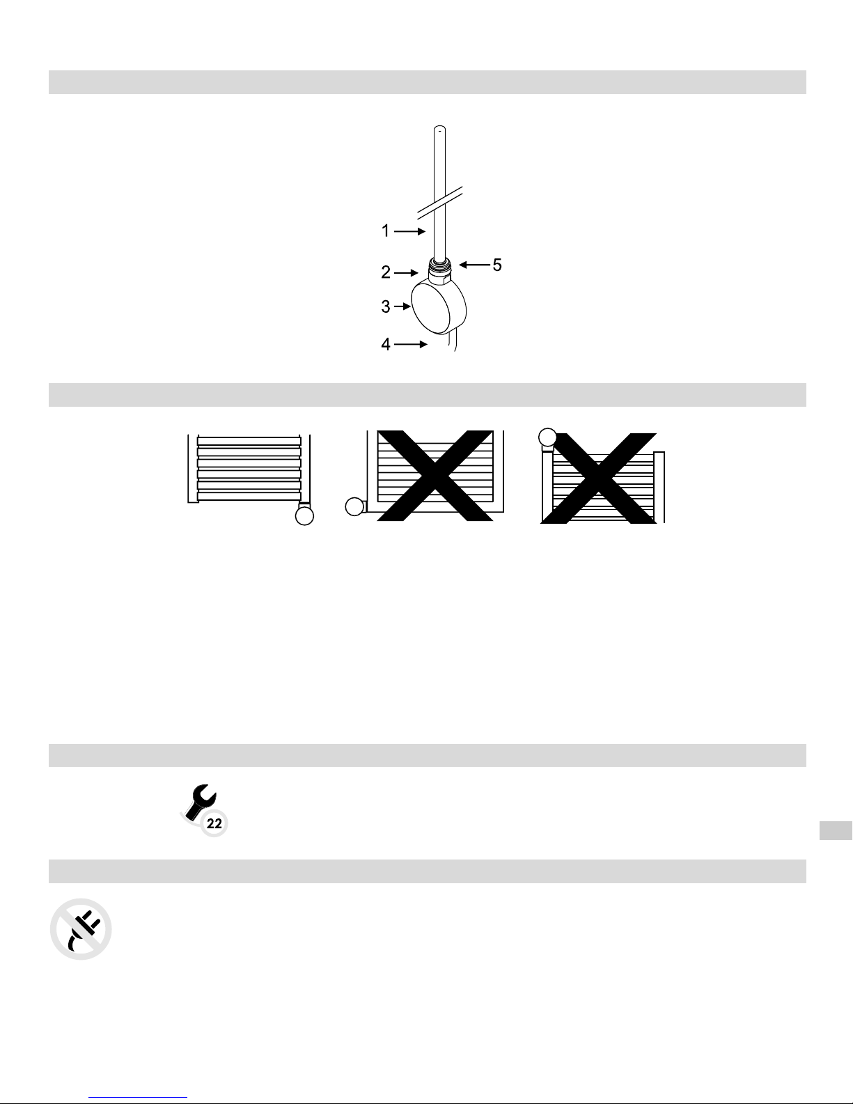
CONSTRUCTION OF THE HEATING ELEMENT UNIT
1. Heating element
2. Heating element head
3. Control head
4. Power wire
5. Gasket
ELECTRIC RADIATOR:
1. Radiator powered by the heating element only, not connected to the central heating system.
2. Water, water with anti-freezing agent or the right type of oil should be used as a heating medium – possibility of
installation and correct use is conditioned by meeting manufacturer's requirements on the radiator and heating
element.
3. Filling the radiator with too much liquid leads to exceeding of acceptable pressure and damaging of the radiator
or heating element. If you are filling the radiator yourself, please act strictly according to the below instructions.
4. Other methods of correct filling of radiator can be found on www.termaheat.pl. Radiator should not be filled with
a heating medium of temperature higher than 65°C.
5. Heating element should not be fitted horizontally or turned downwards.
6. The device should not be twisted or untwisted being held by the enclosure. Always use a spanner for fitting the
unit!
TOOLS REQUIRED FOR INSTALLATION OF HEATING ELEMENT UNIT
– spanner no 22
INSTALLATION OF THE HEATING ELEMENT UNIT
WARNING! The device must not be connected to electricity during installation. Unplug the device
prior to installation.
WARNING! Please take every precaution when filling the radiator in order to avoid being burnt by hot
liquid.
Page 14
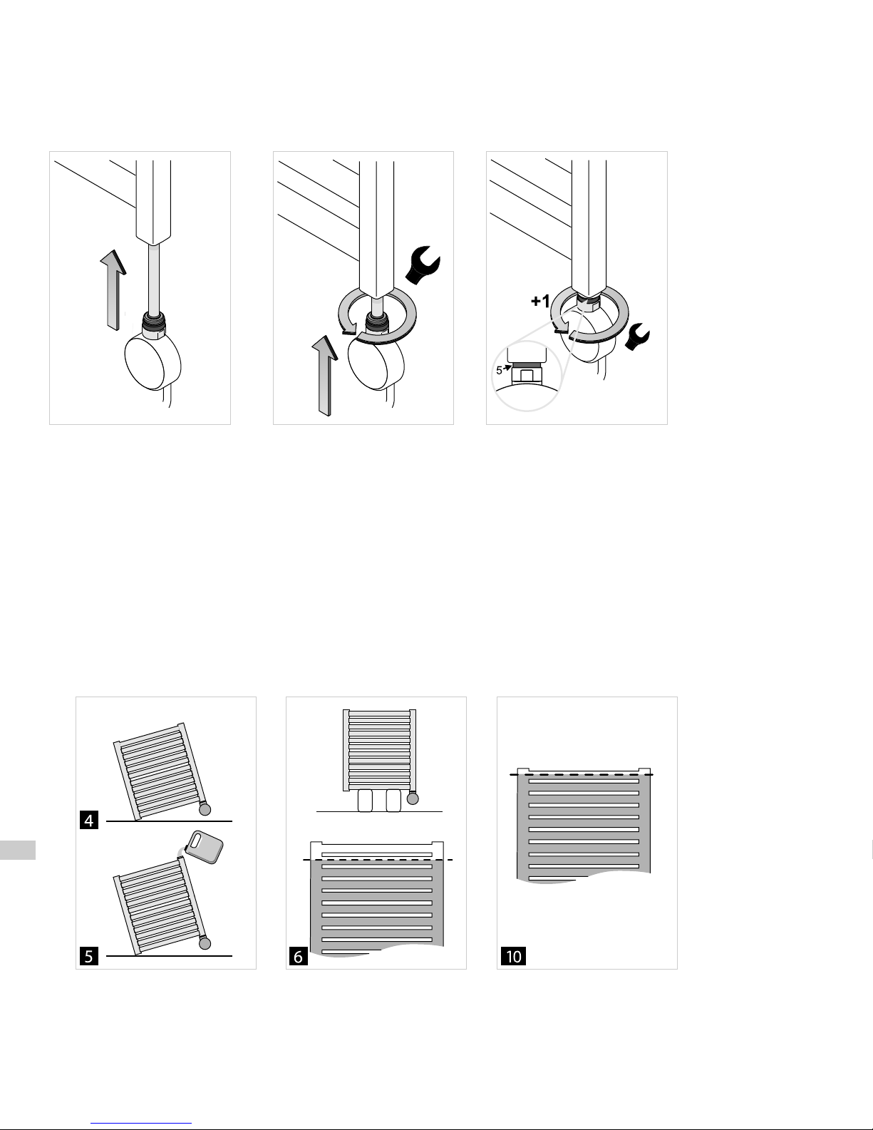
1. Insert heating element (1) into the threaded opening at the bottom end of the collector.
2. Twist the head of the heating element with a spanner no 22 until you feel resistance.
3. Special gasket (5) assures tightness of connection and allows an additional twist and correct positioning of the
front of the control head.
4. Put the radiator in an oblique position to make sure that the upper collector opening is in the highest point!!! The
radiator must not be rested on the heating element control head or any other part of the heating element unit at
any time!!!
5. Fill the radiator with the heating medium.
6. Put the radiator back in the upright position and check the level of the liquid inside it.
7. Make sure that the connection between the radiator and the heating element unit is tight.
8. Connect the device to electricity and turn on the heating element unit (upper collector opening must be open!).
8.1. One can use a hot heating medium of temperature not exceeding 65 C degrees for filling the radiator. In
such case, fill the entire radiator, put it in an upright position and turn the heating element unit on.
9. Set the maximum possible temperature and observe the liquid level rising – the excess liquid may be slopping
through the upper opening in the collector – remove excess liquid in order not to allow for the heating element
control head to be flooded or wetted.
10. When the level of the heating medium stops rising, wait another 5 minutes, turn off the heating element unit and
disconnect the device from electricity.
11. Do not wait until the radiator cools down and pour a small amount of the liquid out – to the mid width of the last
pipe.
12. Close the upper opening of the collector with the dedicated seal and put it back on the wall.
13. Connect the heating element unit to the socket / installation. The device is ready for use.
Page 15
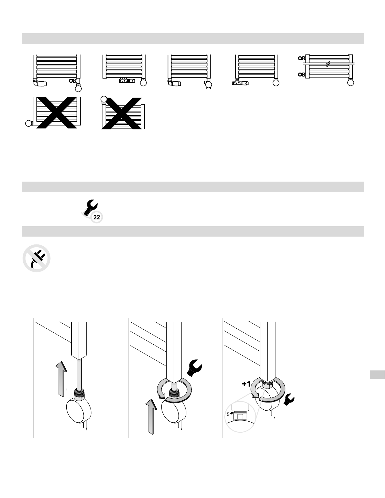
DUAL FUEL radiator:
1. Radiator connected to the system for which heating element unit is installed additionally.
2. Central heating installation must be fitted with the valves enabling disconnecting the radiator from the rest of the
system.
3. It is recommended to bleed the radiator after every longer interval in use.
4. Heating element must not be installed horizontally or turned downwards.
TOOLS REQUIRED FOR INSTALLATION OF HEATING ELEMENT UNIT
– spanner no 22
INSTALLATION OF THE HEATING ELEMENT UNIT
WARNING! The device must not be connected to electricity during installation. Unplug the device
prior to installation.
1. In case of a radiator connected to the central heating system, close both valves and remove the heating
medium.
2. Insert the heating element (1) into the threaded opening at the bottom end of the collector.
3. Twist the head of the heating element using a spanner no 22.
4. Special gasket (5) assures tightness of connection and allows an additional twist and correct positioning of the
front of the control head.
central heating
Page 16
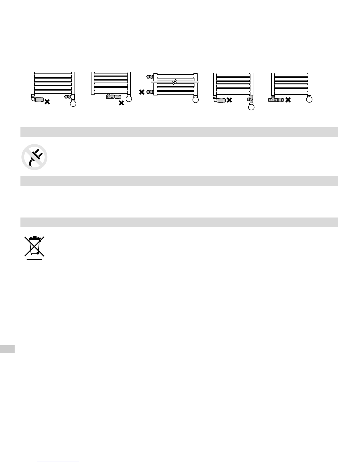
5. Open the valves, fill the radiator with the heating medium from the installation and bleed it.
6. Make sure that the connection between the radiator and the heating element unit is tight.
7. Close one of the valves before using the heating element unit and leave the other one open! (we recommend
that you close the thermostatic valve).
Always make sure that one of the valves is open prior to using the heating element unit!!
8. Connect the heating element unit to the socket / installation. The device is ready for use.
DEVICE DISASSEMBLY
1. In case of a radiator connected to a central heating system, close the valves and remove the
heating medium. For electric radiators – take it off the wall and position it in such a way to
unable pouring the heating medium out of the radiator during disconnecting the heating element.
2. Untwist the heating element using a spanner no 22.
MAINTENANCE
1. Disconnect the device from electricity prior to cleaning.
2. Heating element control head should be cleaned with a dry or damp cloth with a very small amount of
detergents, which should never contain any solvents or abrasive agents.
PRODUCT DISPOSAL
This product should not be disposed of as domestic waste but should be brought to the appropriate
collection point for recycling of electric and electronic devices. This information is provided by the
sign on the product, user manual and packaging. Information on the appropriate point for used
devices can be provided by Your local distributor or manufacturer of the product. Thank You for Your
effort towards environment protection.
Page 17
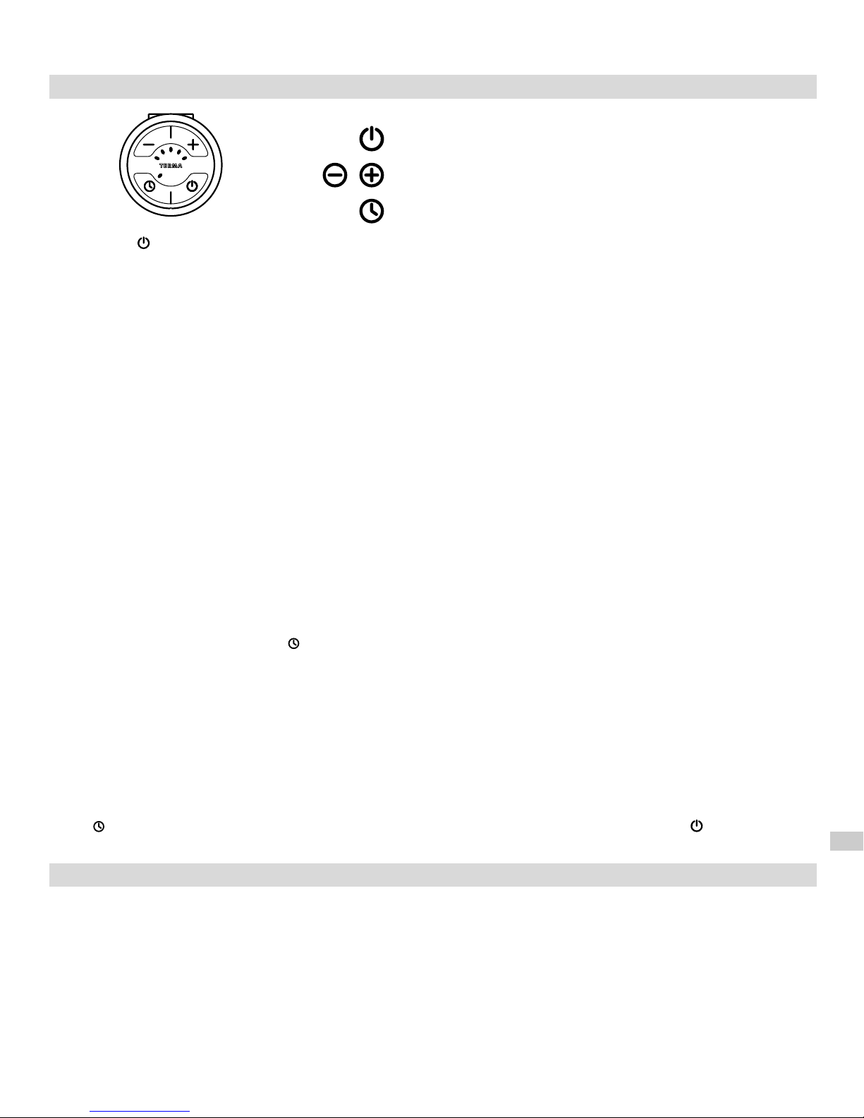
FUNCTIONS AND USE OF DEVICE (SOA)
→ ON/OFF button
→ Heating output regulation
→ TIMER button
Pressing the button switches on the device, after which, the element will begin to heat. By turning itself on and off
regularly, the device regulates the heating output of the radiator to an average temperature, as set by the user within
30-100% of nominal heating output of the device.
The design of the device (PTC heating element) protects the user from harm via burning, by automatically limiting
radiator temperature to 60°C, regardless of the current setting (provided that the heat output of the element has
been correctly matched with the heat output of the radiator).
The design of the device as well as physical characteristics of heating medium inside the radiator influence the way
in which heat is distributed throughout radiator – temperature of the pipes at the bottom of the radiator (especially
the two located at the very bottom of it), may be lower than the temperature of the remaining parts of the radiator –
this is a normal phenomenon.
Setting of required heating output:
In order to obtain the required room temperature, please set the right heating level of the device (buttons +/-).
It is possible to set 1 of 5 heating levels: 30-40-60-80-100% of the nominal heating output.
Selection of every subsequent level is indicated by switching on subsequent diodes.
TIMER Function
TIMER function allows programming of the device to heat for 2 hours with a different heat output, for instance in
order to dry a towel. After this period of time the device automatically returns to the setting from before the 2-hour
dryer activation.
TIMER is turned on by pressing the button (also when the device is off). The device will start working with the
heat output currently set. Settings can be modified as required while the device is working (buttons + and -).
If the device was off before the timer mode was activated, it will turn off automatically on termination of the timer.
If the device was set to i.e. setting 2 before the timer mode was activated, and is then modified to i.e. setting 4, the
device will return to setting 2 after 2 hours.
Attention: if the device is on and settings are not modified on activation of TIMER, settings will not change after 2
hours. It will still operate on the same setting.
Press button at any time to stop the TIMER mode. Turning the device off and back on with the button will also
deactivate the function.
ANTI-FREEZE FUNCTION (Anti-freeze protection)
When the device is off and the temperature around temperature sensor drops to below 6°C, the device will switch on
automatically. This is to prevent the heating medium inside the radiator from freezing. Activating Anti-freeze mode is
indicated by flashing of the centre diode.
Page 18
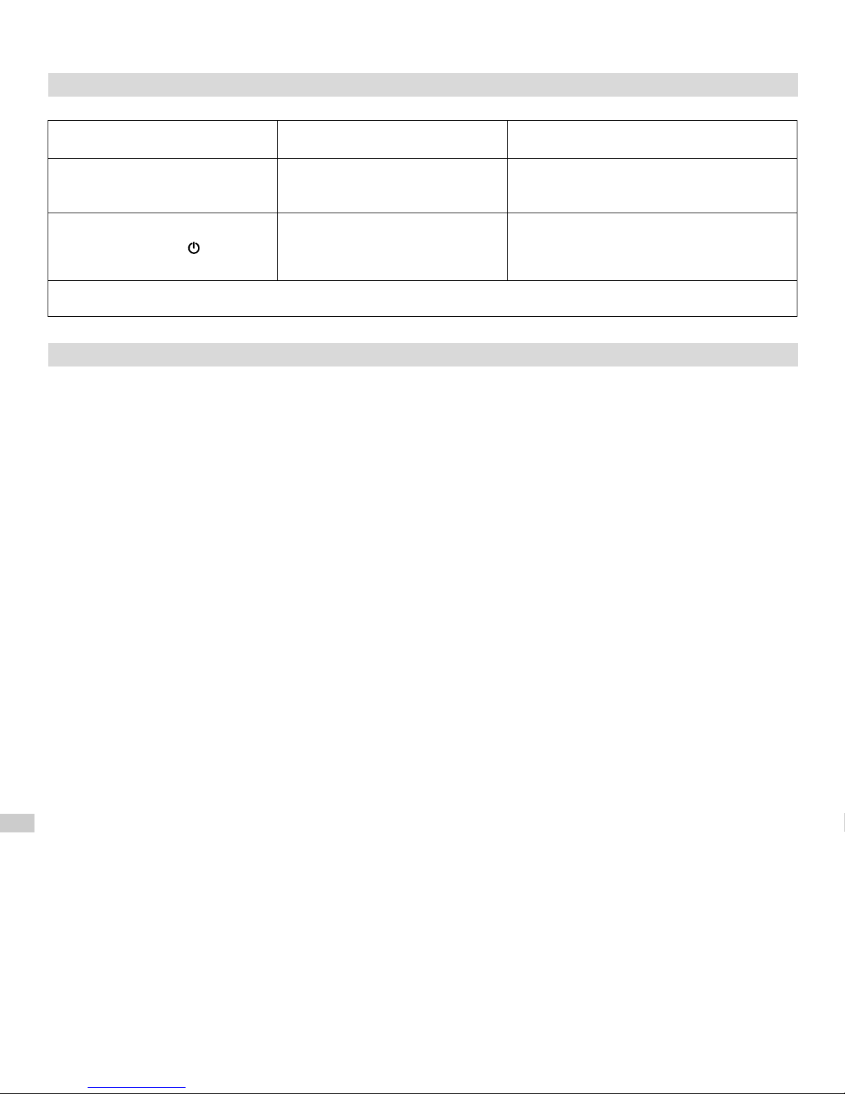
TROUBLESHOOTING
Problem Possible cause
Device is connected to
electricity, no diodes are on
Connection problem
Device heats despite having
been turned off with button
Electronics problem
If the problem persists, please contact your local distributor
Problem solution
Check power lead is plugged into power
socket and that power switch is on
Disconnect the device completely from
electricity and wait until the radiator cools
down. Turn the device back on
WARRANTY TERMS & CONDITIONS
1. Subject of this warranty is a heating element of Terma Sp. z o.o. Name of the model as well as product features
have been specified on the packaging.
2. By accepting the device on purchase, the Client confirms that the product is of full value. The Client should
immediately inform the Seller of any discovered faults – otherwise it will be understood that the Product was
faultless at the time of purchase. This refers especially to any faults or damages of the control panel case.
3. Warranty period for the Product is 24 months from the date of purchase, but no longer than 36 months from date
of production.
4. Any claims made will be processed on production of the warranty card and the evidence of purchase.
Manufacturer has the right to reject any claim on the grounds of not presenting any of the above documents.
5. This warranty does not comprise any faults that are due to:
– incorrect (not in accordance with the manual) installation, use or disassembly,
– incorrect use of the heating element (ie. for any purpose that is not specified by the Manufacturer as intended
for this type of product),
– Product being handled by unauthorized persons,
– any faults or damages caused by the Client after having purchased and accepted the Product.
6. Central heating installation should be fitted with lock-shield valves, enabling disassembly of the radiator or the
heating element and its control head without the necessity of emptying the whole system of the heating medium.
Any problems or expenses arising from lack of such valves in the installation cannot not be used as the grounds
for any claims against Terma.
7. The attached Product Manual is an integral element of the Warranty. Please read it carefully prior to the Product
installation and use.
8. The Manufacturer is obliged to remove any production fault within 14 working days from receipt of the faulty
device to Manufacturer's premises.
9. Should the repair turn out impossible, Manufacturer is obliged to replace the faulty Product with a new, full-value
unit of identical parameters.
Page 19
Unsere Produkte wurden mit dem Gedanken entworfen, Ihre Bedürfnisse, laut den höchsten Qualitäts-,
Funktionalitäts- und Sicherheitsstandards zu erfüllen.
Wir gratulieren zum gelungenen Einkauf und wünschen viel Zufriedenheit beim Gebrauch Ihres neuen Gerätes.
HINWEISE ZUM SICHEREN BETRIEB
Lesen Sie mit Aufmerksamkeit die untere Gebrauchsanweisung und machen Sie sich mit den Illustrationen vertraut.
1. Benützen Sie in keinem Fall ein Gerät, welches dem Anschein nach beschädigt sein könnte.
2. Vor dem Einschalten des Gerätes, prüfen Sie, ob die Spannung auf dem Messgerät mit der Spannung auf Ihrer
elektrischen Installation übereinstimmt.
3. Kontrollieren Sie regelmässig, ob das Netzkabel nicht beschädigt wurde und der Gebrauch ungefährdet ist.
4. Das beschädigte Netzkabel kann nicht repariert werden und muss vom Produzenten oder Fachmann ersetzt
werden.
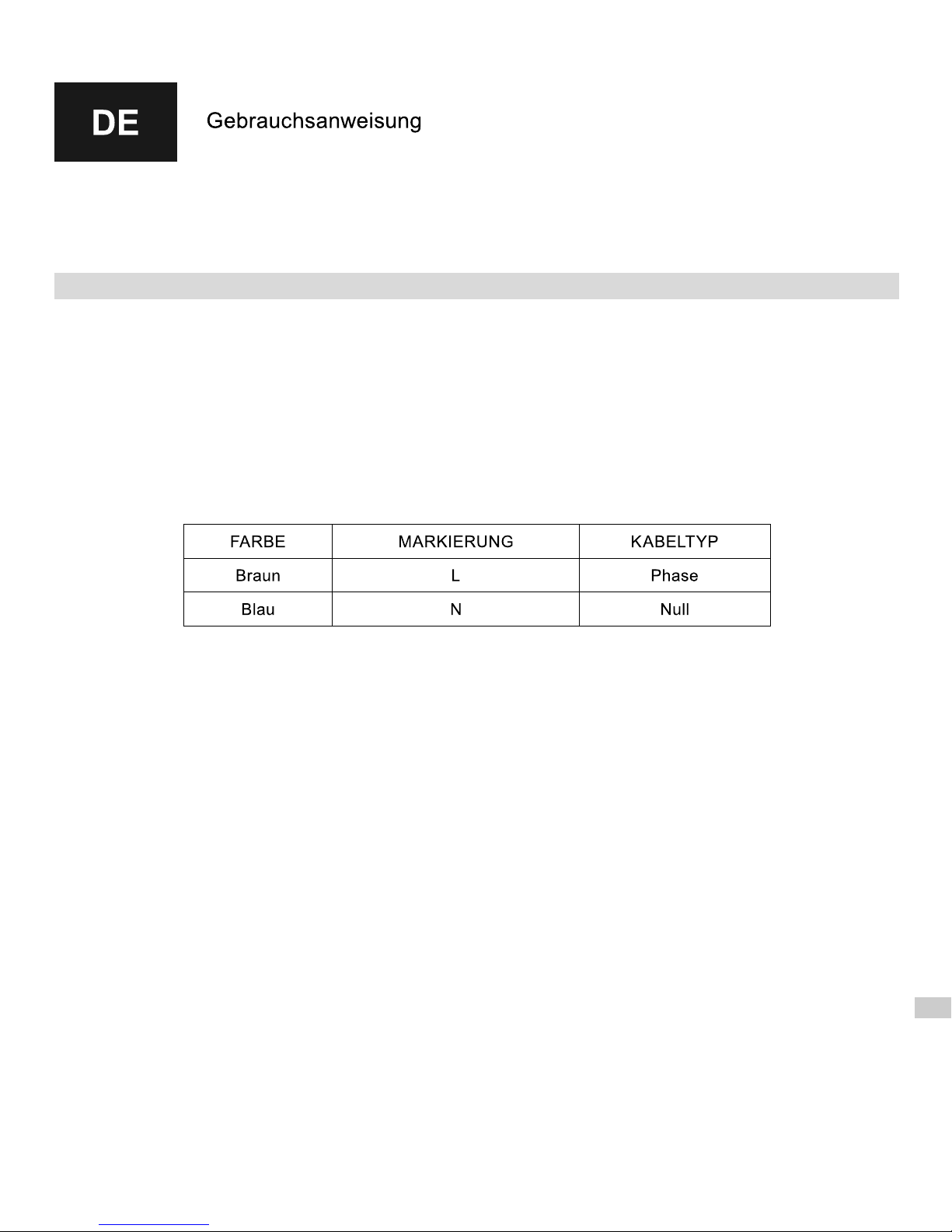
Bei der Version ohne Stecker (z.B. Montage direkt an das Stromnetz), sieht die Farben- Kennzeichnung der
Leitungen wie folgt aus:
6. Die Heizpatrone ist dazu bestimmt um im Heizmedium zu arbeiten und darf nicht im Trockenen eingeschaltet
werden. Die Arbeit der Heizpatrone in freier Luft darf nicht länger als 5 Sekunden betragen.
Aus Sicherheitsgründen ist das Berühren der Metall- Elemente verboten, da Verbrennungen entstehen können.
Verhindern Sie, dass die Leitung mit dem heissen Heizelement in Berührung kommt.
7. Während der Montage, darf sich das Gerät nicht unter Spannung befinden. Nehmen Sie dazu den Stecker aus
der Steckdose heraus oder trennen die Verbindung der Leitung zum Stromnetz.
8. Das Gehäuse darf nicht geöffnet werden.
9. Heizpatrone vor Wasser schützen.
10. Während dem Aufenthalt in der Badewanne, Dusche oder stehend auf nasser Fläche, ist das Bedienen des
elektrischen Gerätes aus Sicherheitsgründen verboten.
11. Die Leistungskraft der Heizpatrone darf die 100% Leistung des Heizkörpers bei folgenden Parameter:
75/65/20°C nicht überschreiten
12. Der Druck im Heizkörper darf die vom Heizkörperhersteller genannten Werte nicht überschreiten und für die
Heizpatrone nicht mehr als 10 Atm. betragen. Überdruck kann zu Sachschäden führen und eine Beschädigung
des Heizkörpers oder der Heizpatrone verursachen, was Gefahr für Leib und Leben darstellt.
13. Im Elektroheizkörper sollte ein Luftkissen mit dem entsprechenden Volumen zurücklassen werden (siehe
Installation).
14. Im Heizkörper der im Mischbetrieb arbeitet (Wasser- und Elektrobetrieb) und an die Zentralheizung angeschlossen
ist, sollte vor dem Einschalten der Heizpatrone aber auch während dem Heizen, eines der Ventile offen gelassen
werden, damit das durch Hitze entstandene Übermass von Wasser leichter ausgestossen werden kann.
Geschlossene Ventile führen zu enorm steigendem Druck im Heizkörper, was einen Sachschaden des
Heizkörpers oder der Heizpatrone verursachen kann (siehe Wasser- und Elektroheizkörper/ Installation).
15. Das Gerät ist ausschließlich für den Hausgebrauch vorgesehen.
16. Es ist untersagt, dieses Gerät von Kindern , geistig behinderten Personen oder solcher, die kein genügendes
Wissen oder Erfahrung in Bedingung von Geräten dieser Art besitzen, zu betätigen. In so einem Falle, wird eine
Aufsicht benötigt, oder muss eine Schulung , derfür ihre Sicherheit zuständigen Person, durchgeführt werden.
Page 20
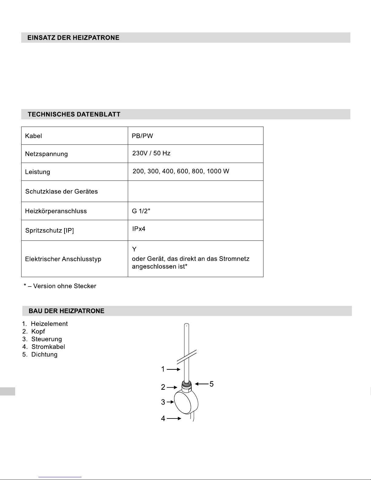
Heizpatronen von Terma, welche in Heizkörpern installiert werden, dienen der Erwärmung von Räumen als auch
Trocknung von Handtücher und Wäsche. Die Heizpatrone kann sowohl in einem rein elektrischen-, wie auch im
Mischbetrieb arbeiten.
Die Heizpatronen sind dazu bestimmt nur in geschlossenen Installationen zu arbeiten (nicht offen zur Atmosphäre).
Klase II
Page 21
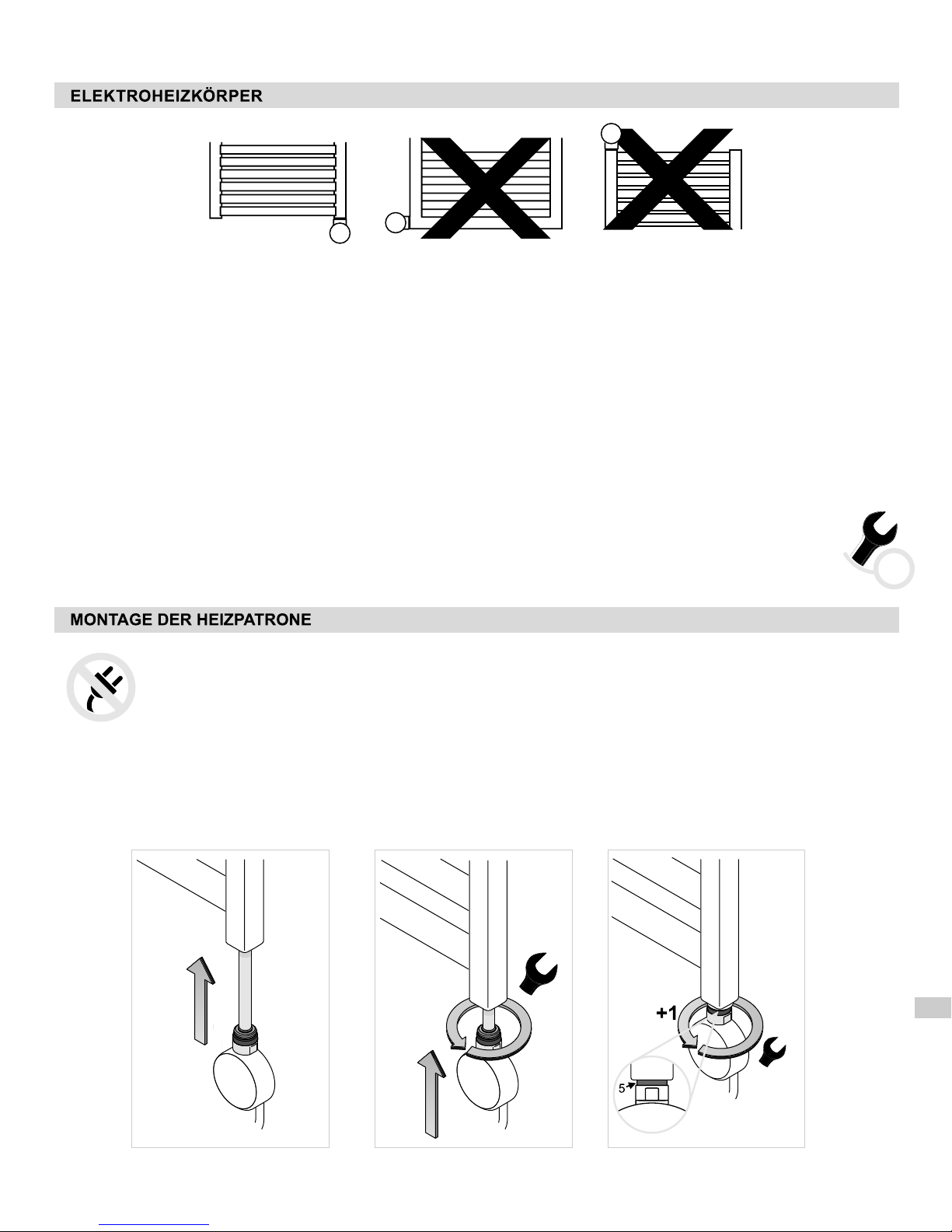
1. Heizkörper wird nur mit einer elektrischen Heizpatrone betrieben und somit nicht an die Zentralheizung
angeschlossen.
2. Das Heizmedium kann in folgender Gestalt auftreten: Wasser, Wasser mit Zusatz von Anti- Gefriermittel, oder
bestimmtes Öl. Wenn der Heizkörper fachgerecht montiert und genutzt werden soll, müssen einige Anforderungen
des Heizkörper- und Heizpatronenproduzenten erfüllt werden.
3. Bei übermässigem Auffüllen der Flüssigkeit im Heizkörper, kann es zur Überschreitung des zugelassenen Druckes
führen, wobei der Heizkörper oder die Heizpatrone beschädigt werden können. Falls das Füllen des Heizkörpers
selbstständig erfolgen soll, muss strikt nach der Anweisung für das richtige Füllen des Heizkörpers vorgegangen
werden, so wie es unten aufgeführt ist.
4. Andere Methoden für fachgerechtes Füllen des Heizkörpers finden Sie auf der Seite: www.termaheat.pl. Es wird
nicht empfohlen, den Heizkörper mit einer höheren Temperatur als 65° Celsius aufzufüllen.
5. Die Heizpatrone darf nicht waagrecht in den Heizkörper montiert werden und mit dem Heizelement nach unten
ausgerichtet sein. Bei dem Ein- und Ausschrauben der Heizpatrone wird nicht empfohlen, die Heizpatrone an
Ihrem Gehäuse festzuhalten. Dafür muss ein Montageschlüssel verwendet werden!
Werkzeuge zur Montage der Heizpatrone:
– schmaler Montageschlüssel Grösse 22
22
ACHTUNG! Während der Montage darf das Gerät nicht an Strom angeschlossen sein. Nehmen Sie den
Stecker aus der Steckdose heraus.
ACHTUNG! Vorsicht bewahren während des ganzen Füllprozesses des Heizkörpers, damit
Verbrennungen des heissen Heizmedium verhindert werden können!
1. Schieben Sie das Heizelement (1) in die untere Gewinde- Öffnung des Heizkörper- Kollektoren ein.
2. Den Kopf mit Hilfe des schmalen Montageschlüssels Grösse 22 zudrehen.
3. Spezielle Abdichtung (5) versichert Dichtung der Verbindung und ermöglicht 1 zusätzliche Drehung der
Heizpatrone, so dass die Heizpatronen- Front richtig platziert ist.
Page 22
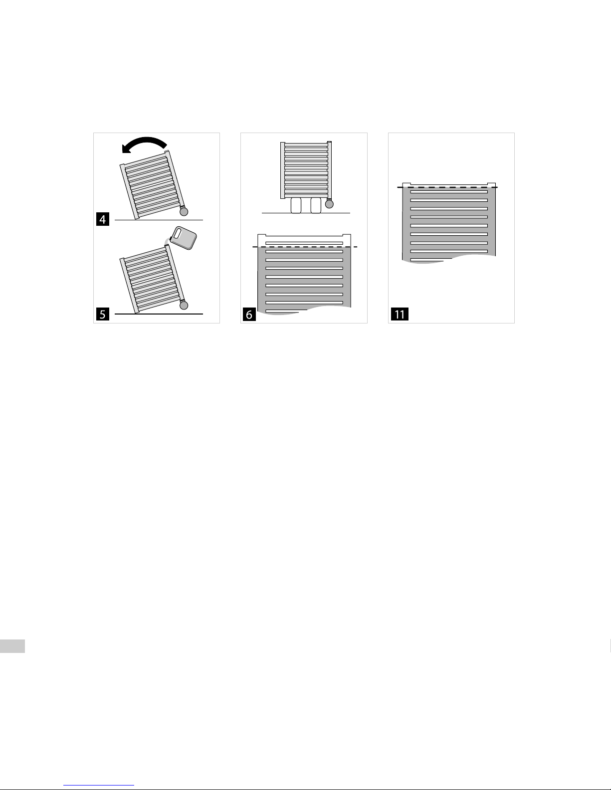
4. Den Heizkörper leicht schräg aufstellen, so dass sich die Einfüllöffnung zuoberst befindet!
Der Heizkörper darf in keinem Fall auf der Steuerung der Heizpatrone oder auf einer der Verbindungselemente
gestützt werden!
5. Füllen Sie den Heizkörper mit dem Heizmedium.
6. Heizkörper gerade aufstellen und den Flüssigkeitsspiegel kontrollieren.
7. Stellen Sie sicher, dass die Verbindung zwischen Heizkörper und Heizpatrone verdichtet ist.
8. Das Gerät an die Steckdose anschliessen und die Heizpatrone einschalten (obere Öffnung bleibt offen!).
8.1. Beim Füllen des Heizkörpers mit dem heissen Heizmedium, darf die Temperatur nicht mehr \ als 65° Celsius
betragen.
8.2. In diesem Fall, füllen Sie den Heizkörper bis oben, stellen Ihn aufrecht und schalten die Heizpatrone ein.
9. Schalten Sie die Heizpatrone auf Ihre maximale Leistungskraft ein und beobachten Sie dabei, wie der
Flüssigkeitsspiegel im Heizkörper steigt- zu viel Heizmedium, kann zum Überschreiten der Flüssigkeit durch die
obere Öffnung führen- entfernen Sie dabei schnell das herausfliessende Heizmedium, so dass rechtzeitig
verhindert werden kann, dass die Flüssigkeit ins Innere der Heizpatronensteuerung gelangt.
10. Wenn das Heizmedium aufhört sein Volumen zu vergrössern, 5 Minuten abwarten und die Heizpatrone
ausschalten. Danach nehmen Sie den Stecker des Gerätes aus der Steckdose heraus.
11. Ohne abzuwarten bis der Heizkörper abgekühlt ist, nehmen Sie den Heizkörper vorsichtig herunter und giessen
die übermässige Flüssigkeit ab- bis das Heizmedium den Stand des letzten Heizkörperröhre erreicht hat.
12. Schliessen Sie die obere Öffnung mit dem entsprechenden Stöpsel ab und befestigen Sie erneut den
Heizkörper an die Wand.
13. Die Heizpatrone an die Steckdose / Installation anschliessen. Das Gerät ist nun arbeitsbereit.
Page 23
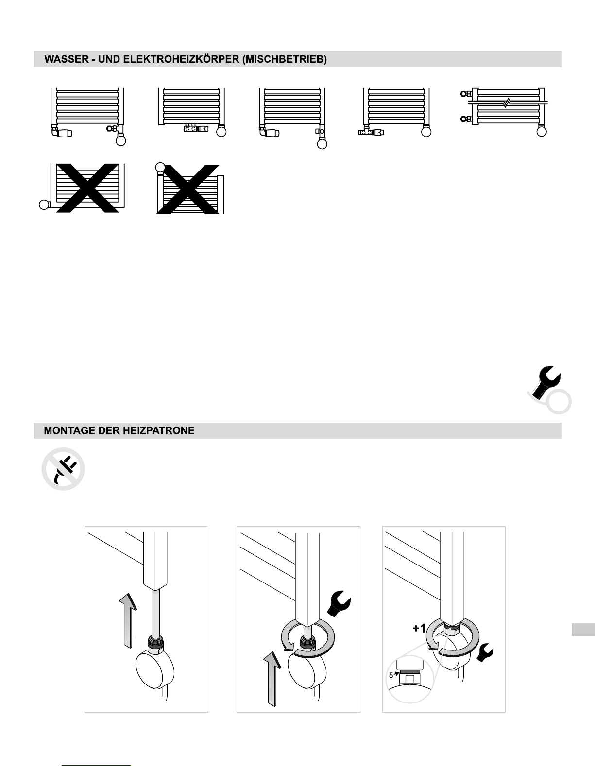
1. Heizkörper ist an die Zentralheizung angeschlossen. Zusätzlich wird eine elektrische Heizpatrone montiert.
2. Die Installation der Zentralheizung muss mit entsprechenden Ventilen ausgestattet sein, so dass eine
Absperrung des Heizkörpers möglich ist (Mischbetrieb).
3. Die Temperatur der Zentralheizung darf nicht mehr als 82 Celsius betragen!
4. Bei längerer Gebrauchs- Pause wird eine Entlüftung des Heizkörpers empfohlen. Die Heizpatrone ist mit einer
Sicherung ausgestattet, die den Heizkörper vor der „Arbeit im Trockenen“ (ohne Heizmedium) schützt. Wenn
dies jedoch auftritt, muss die Heizpatrone zur Reperatur beim Produzenten abgegeben werden (besteht keine
Garantie).
5. Die Heizpatrone darf nicht waagrecht in den Heizkörper montiert werden und mit dem Heizelement nach unten
ausgerichtet sein.
°
Werkzeuge zur Montage der Heizpatrone:
– schmaler Montageschlüssel Grösse 22
22
ACHTUNG! Während der Montage darf das Gerät nicht an Strom angeschlossen sein.
Nehmen Sie den Stecker aus der Steckdose heraus.
1. Bei dem an die Zentralheizung angeschlossenen Heizkörper beide Ventile zudrehen und das Heizmedium
entfernen.
Page 24
2. Schieben Sie das Heizelement (1) in die untere Gewinde- Öffnung des Heizkörper- Kollektoren ein.
3. Den Kopf mit Hilfe des schmalen Montageschlüssels Grösse 22 zudrehen.
4. Spezielle Abdichtung (5) versichert Dichtung der Verbindung und ermöglicht 1 zusätzliche Drehung der
Heizpatrone, so dass die Heizpatronen- Front richtig platziert ist.
5. Drehen Sie die Ventile auf und füllen den Heizkörper mit dem aus der Zentralheizung enthaltenden Heizmedium.
Nun entlüften Sie den Heizkörper.
6. Stellen Sie sicher, dass die Verbindung zwischen Heizkörper und Heizpatrone verdichtet ist.
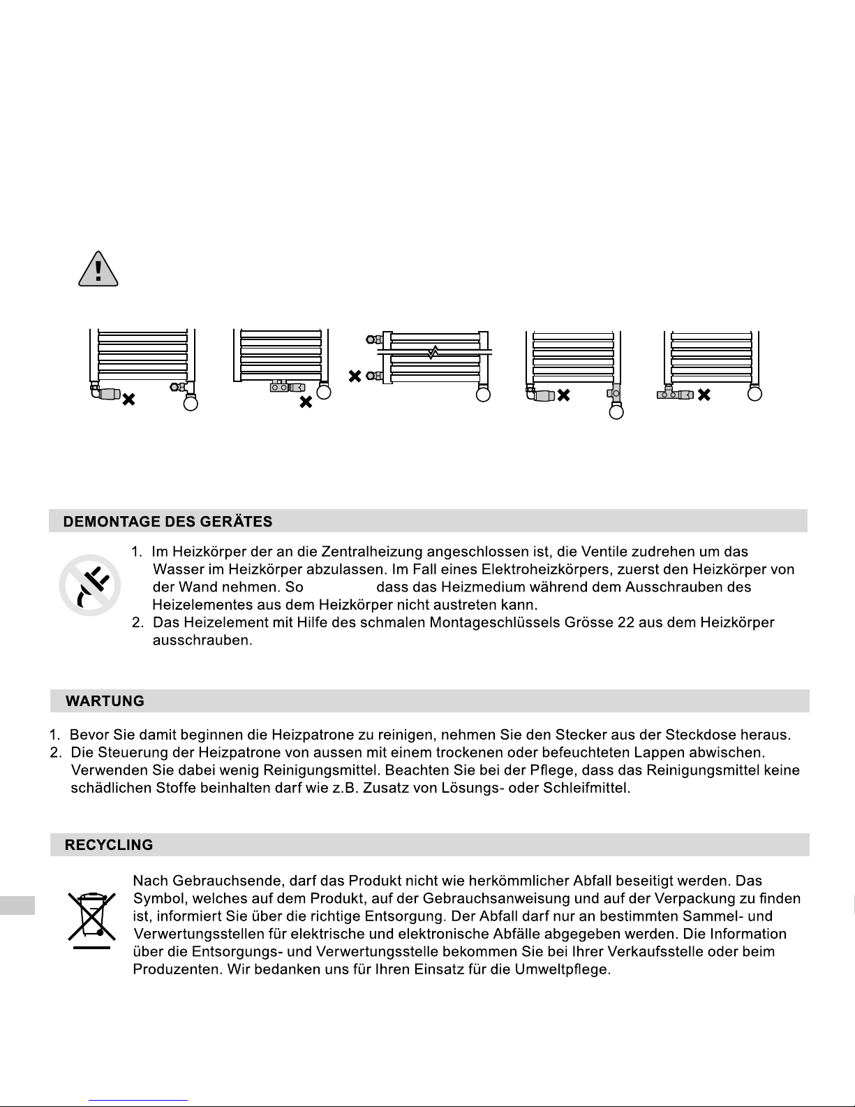
7. Bevor die Heizpatrone eingeschaltet wird, das eine Ventil zudrehen, wobei das andere offen bleiben muss! (Wir
empfehlen das Ventil mit dem Thermostkopf zu schliessen).
Bei jedem Einschalten der Heizpatrone, versichern Sie sich, dass das eine Ventil offen bleibt!
8. Die Heizpatrone an die Steckdose/ Installation anschliessen. Das Gerät ist nun arbeitsbereit.
abstützen
Page 25
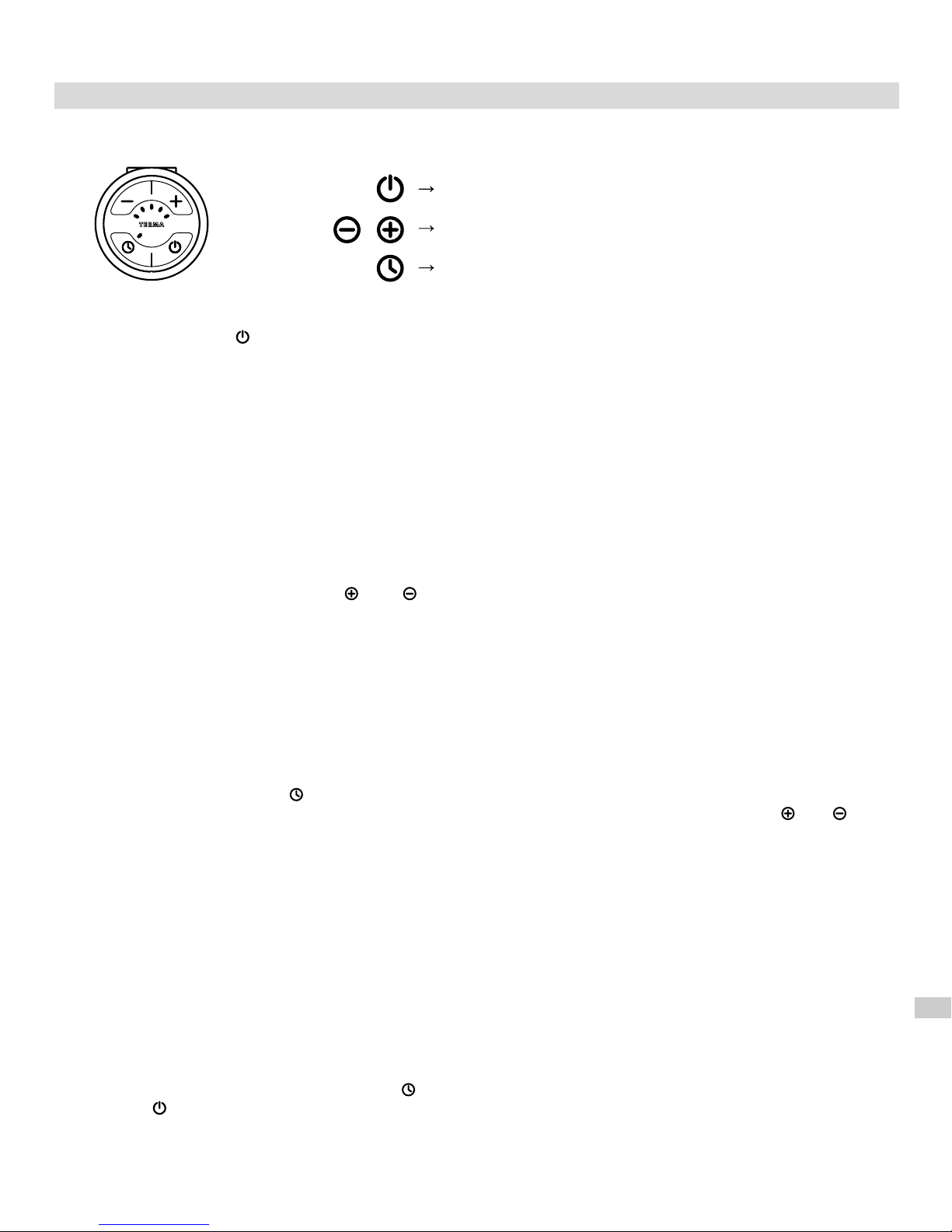
FUNKTIONEN UND BEDIENUNG DES GERÄTES (Modell SOA)
Das Betätigen der Taste schaltet das Gerät ein. Durch zyklisches Ein- und Ausschalten, heizt
die Heizpatrone den Heizkörper auf und setzt die Arbeit mit durchschnittlichen Leistung fort, welche
vom Benutzer im Bereich von 30-100% (der nominalen Leistung des Gerätes), eingestellt worden ist.
Der Bau der Heizpatrone (Heizelement PTC) schützt unabhängig von der aktuellen Einstellung, vor eventuellen
Verbrennungen, indem sie die maximale Heizkörpertemperatur von 60°C begrenzt (unter Bedingung, dass die
Leistung des Heizelementes richtig zur Heizkörperleistung angepasst wurde).
Die Heizpatronen- Konstruktion, sowie die physikalischen Eigenschaften des Heizmediums, führen dazu, dass
die untersten Heizkörperrohre (hauptsächlich die zwei untersten), eine niedrigere Temperatur aufweisen als der
Rest des Heizkörpers- Das ist ganz normal.
Um den entsprechenden Wärmekomfort im Raum zu erreichen, muss die richtige Heizleistungsstufe der
Heizpatrone eingestellt werden (Tasten oder ).
Möglich ist 1 von 5 Einstellungen der Leistungsstufen: 30 - 40 - 60 - 80 - 100% der nominalen Leistung.
Das Wählen eines höheren Arbeitsbereiches, wird durch das Leuchten einer weiteren Diode signalisiert.
Die TIMER- Funktion erlaubt das Gerät so zu programmieren, dass es für 2 Stunden mit einer anderen Leistung
heizt (z. B bei Trocknung eines Badehandtuches). Nach Ablauf dieser Zeit, kehrt die Heizpatrone zum
ursprünglichen Arbeitsstand zurück, bevor dass die Funktion eingeschaltet wurde.
Der TIMER wird durch die Taste betätigt (auch wenn die Heizpatrone ausgeschaltet ist). Mit der aktuell
eingestellten Leistung, beginnt das Gerät seine Arbeit. Die Einstellung kann jederzeit mit den Tasten oder
geändert werden.
Wenn die Heizpatrone vor dem Einschalten des TIMERS ausgeschaltet war, dann schaltet das Gerät nach
Trocknungsende selbstständig aus.
Falls die Heizpatrone vor Aktivierung des Trockners z.B. auf Einstellung 2 eingestellt war und nach dem
Einschalten des TIMERS die Einstellung manuell geändert wird, z.B. auf Einstellung 4, dann kehrt die
Heizpatrone nach Ablauf von 2 Stunden wieder zur Einstellung 2 zurück.
Achtung: Wenn die Heizpatrone eingeschaltet ist und nach Betätigen der Taste TIMER die Einstellung nicht
modifiziert wird, dann wird nach Ablauf von 2 Stunden keine Änderung vorgenommen. Die Heizpatrone wird
weiterhin auf der aktuellen Einstellung arbeiten.
Um die Arbeit des TIMERS abzubrechen, Taste drücken. Das Aus- und erneute Einschalten der Heizpatrone
mit der Taste deaktiviert die Funktion.
Ein- oder Ausschalten der TIMER- Funktion
Ein- und Ausschalten der Heizpatrone
Einstellung der Heizleistung
TIMER- Funktion
EINSTELLUNG DER HEIZLEISTUNG
Page 26
1. Diese Garantie gilt für Heizpatronen, welche durch Terma Sp. z o.o. hergestellt worden sind. Modell
und die wichtigsten Merkmale wurden auf der Verpackung beschrieben
2. Mit der Produktabnahme bestätigt der Kunde die Vollwertigkeit des Produktes. Bei der Feststellung von jeglichen
Mängeln, sollte der Verkäufer sofort in Kenntnis gesetzt werden – in anderem Falle wird angenommen,dem
Kunden wurde ein mangelfreies Produkt verkauft. Dies betrifft vor allem die Oberfläche der Steuerung
3. Garantie beträgt 24 Monate vom Kaufdatum, aber nicht länger als 36 Monate vom Produktionsdatum..
4. Voraussetzung der Inanspruchnahme einer Garantieleistung ist der Kaufbeleg. Wird dieser nicht vorgelegt,
verfügt der Hersteller über das Recht, den Garantieanspruch abzuweisen.
5. Die Garantie betrifft keine Beschädigungen die aus folgenden Gründen entstanden sind:
– auf Grund einer falschen (nicht mit der Betriebsanweisung übereinstimmenden) Montage, Bedienung oder
Demontage.
– auf Grund der Benutzung des Heizelementes, welche nicht mit dessen Bestimmung übereinstimmt
– nach Eingriff in das Gerät von dazu unbefugten Personen
– aus Schuld des Kunden nach dem Kauf
6. Die Heizungsanlage sollte mit Ventilen ausgestattet werden, die eine Demontage des Heizkörpers bzw.
Heizpatrone ohne Entleerung der gesamten Anlage zu ermöglichen. Probleme oder Kosten, die durch das
Fehlen solcher Ventile in der Anlage entstehen, werden nicht von Terma übernommen.
7. Die Bedienungsanleitung ist ein integraler Teil der Garantiekarte. Aus diesem Grund sollte diese vor
Inbetriebnahme des Produktes gründlich gelesen werden.
8. Der Hersteller verpflichtet sich zur Fehlerbeseitigung innerhalb von 14 Tagen vom Eingang des bemängelten
Produktes in den Firmensitz.
9. Sollte der Fehler nicht beseitigt werden, stellt der Hersteller ein neues, funktionsfähiges Exemplar mit
denselben Parametern zur Verfügung.
Verbindung der Netzleitung,
Stecker und Steckdose müssen
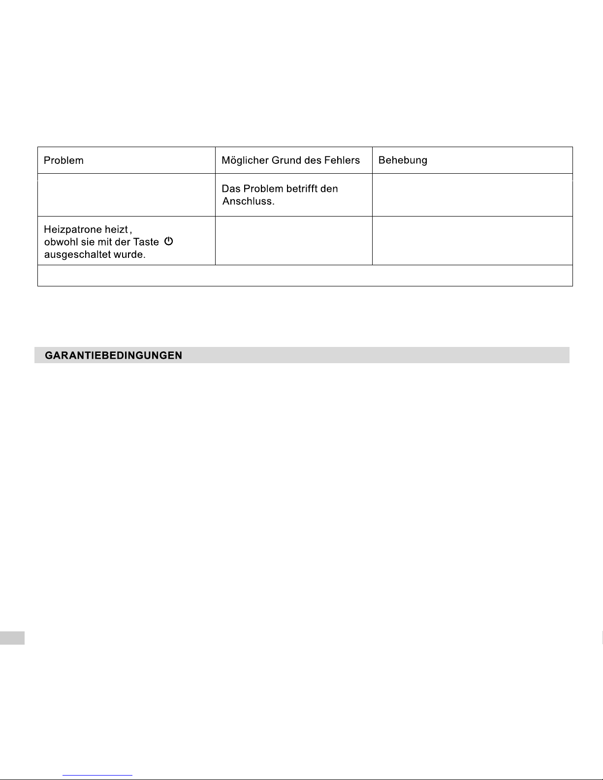
geprüft werden.
Heizpatrone ist an das
Stromnetz angeschlossen.
Keine Diode leuchtet.
Schalten Sie das Gerät ganz vom Netz
aus und warten bis es abkühlt. Dann
erneut anschliessen und einschalten.
Wenn das Problem nicht gelöst werden konnte, dann setzen Sie sich mit Ihrer Verkaufsstelle in Verbindung.
Schaden betrifft möglicherweise
die Elektronik
Wenn die Heizpatrone ausgeschaltet ist und die Temperatur in der Gegend des Temperatursensors unter die
Schwelle von 6°C sinkt, wird die Heizpatrone automatisch eingeschaltet, so dass das Einfrieren des
Heizmediums im Heizkörper verhindert werden kann. Das Blinken der mittleren Diode, signalisiert die
Erkennung von zu niedrigen Temperatur.
FEHLERBEHEBUNG
ANTI-FREEZE FUNKTION (Anti- Gefrierschutz)
Page 27
Nos produit ont été conçus et fabriqués pour répondre à toutes les exigeances de qualité, de fonctionnalité et
d'esthétique. En vous félicitant de votre achat, nous vous souhaitons beaucoup de satisfaction dans l'usage de nos
produits.
CONSIGNES DE SÉCURITÉ
Lire attentivement le mode d'emploi ci-dessous et prendre connaissance des dessins.
1. Ne jamais utiliser l'appareil s'il est endommagé.
2. Avant d'installer l'appareil, vérifier si la tension indiquée sur la plaque signalétique correspond à la tension de
votre habitation.
3. Contrôler régulièrement si le câble d'alimentation n'a pas été endommagé et s'il est utlisé en toute sécurité.
4. Câble d'alimentation ne peut pas être réparé. Endommagé, il doit être remplacé par le fabricant ou un atelier de
réparation spécialisé.
Pour la version sans fiche (p.ex. montage direct dans la boîte de jonction) voir les codes couleurs des fils :
5. Le kit résistance est conçu pour fonctionner dans un liquide. Marche à sec ne doit pas dépasser 5 secondes.
Ne pas toucher les parties en métal : risque de brûlures. Ne jamais laisser le câble d'alimentation en contact
avec la résistance chaude.
6. Lors du montage, l'appareil ne doit pas être sous tension. Retirer la fiche de la source d'alimentation.
7. Ne jamais ouvrir le boîtier.
8. Ne jamais laisser mouiller le boîtier.
10. Debout dans la baignoire, piscine ou pieds nus sur le sol mouillé, ne jamais toucher l'appareil.
11. La puissance de la résistance ne doit pas dépasser 100% de la puissance du radiateur dans les
paramètres 75/65/20°C.
12. La pression dans le radiateur ne doit pas dépasser la valeur indiquée par le fabricant ni la valeur de 10 atm pour
le kit résistance. Le dépassement des pressions admissibles peut provoquer l'endommagement du radiateur, du
kit résistance et, en conséquence, un danger pour la vie et les biens.
13. Dans le radiateur électrique, laisser un coussin d'air du volume approprié (voir → Installation).
14. Dans le radiateur mixte (raccordé à l'installation à eau chaude) avant de mettre l'appareil en marche, laisser une
des vannes ouverte afin de laisser pousser une partie d'eau, causé par la dilatation thermique du fluide
caloporteur. Laisser des vannes fermées provoquera l'augmentation de pression et peut endommager le
radiateur et la résistance (voir → «Radiateur mixte/Installation»).
15. L'appareil est destiné à un usage domestique.
16. L'appareil n'est pas destiné à l'usage des enfants, des personnes de capacités réduites, des personnes sans le
savoir-faire nécessaire pour son usage. Dans le cas contraire, une formation ou surveillance sont nécessaires.
FR
COULEUR LETTRE TYPE DE FILS
Brun
Blue
L
N
Phase
Neutre
Page 28
OBJECTIF DE FONCTIONNEMENT
Kit résistance fabriqué par Terma est un appareil électrique destiné à l'installation dans les radiateurs ou les sècheserviettes. Le kit résistance peut être installé dans le radiateur mixte, fonctionnant hors la période de chauffe, et
dans le radiateur électrique.
Les kits résistances ne sont conçus que pour l'usage dans les systèmes fermés (non ouverts à l'atmosphère).
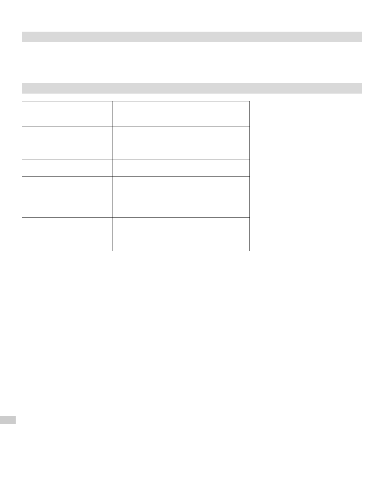
DONNÉES TECHNIQUES
Déscriptif du modèle (type
du câble d'alimentation)
PB / PW
Alimentation 230 V / 50 Hz
Puissances disponibles 200, 300, 400, 600, 800, 1000 W
Classe de protection Classe II
Raccordement G 1/2"
Indice de protection du
boîtier [IP]
IPx4
Type du raccordement
électrique
Y
Ou l'appareil raccordé en permanence à la
source d'alimentation (version sans fiche)
Page 29
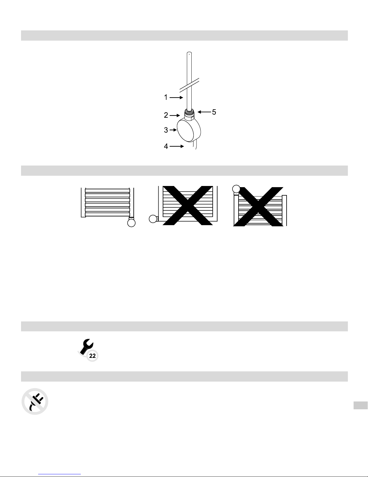
CONSTRUCTION DU KIT RÉSISTANCE
1. Résistance chauffante
2. Tête
3. Boîtier de réglage
4. Câble d'alimentation
5. Joint d'étanchéité
Radiateur ÉLECTRIQUE :
1. Radiateur életcrique avec kit résistance, non raccordé à l'installation à eau chaude.
2. Il est possible d'utiliser comme fluide caloporteur, l'eau, l'eau avec de l'antigel, l'huile approprié : le kit résistance
peut être monté s'il répond aux exigences de son fabricant et du fabricant du radiateur.
3. Dépasser le volume du liquide peut provoquer l'augmentation de la pression et, en conséquence,
endommagement de la résistance ou du radiateur. Lors du remplissage hors usine, suivre strictement les
instructions ci-dessous.
4. Autres méthodes correctes du remplissage du radiateur disponibles sur le site : www.termaheat.pl. Il est interdit
de remplir le radiateur avec du liquide dépassant la température de 65°C.
5. Il est interdit d'installer le kit résistance horizontalement, ni la résistance vers le bas du radiateur.
6. Il est interdit de visser et dévisser l'appareil via le boîtier. Utiliser uniquement la clé de montage !
OUTILS NÉCESSAIRES POUR INSTALLER LE KIT RÉSISTANCE
– clé plate taille 22
INSTALLATION DU KIT RÉSISTANCE
ATTENTION ! Lors du montage, l'appareil ne doit pas être sous tension. Retirer la fiche de la prise.
ATTENTION ! Soyez prudent lors de l'ensemble du processus de remplissage du radiateur afin
d'éviter les brûlures par le fluide caloporteur !
Page 30
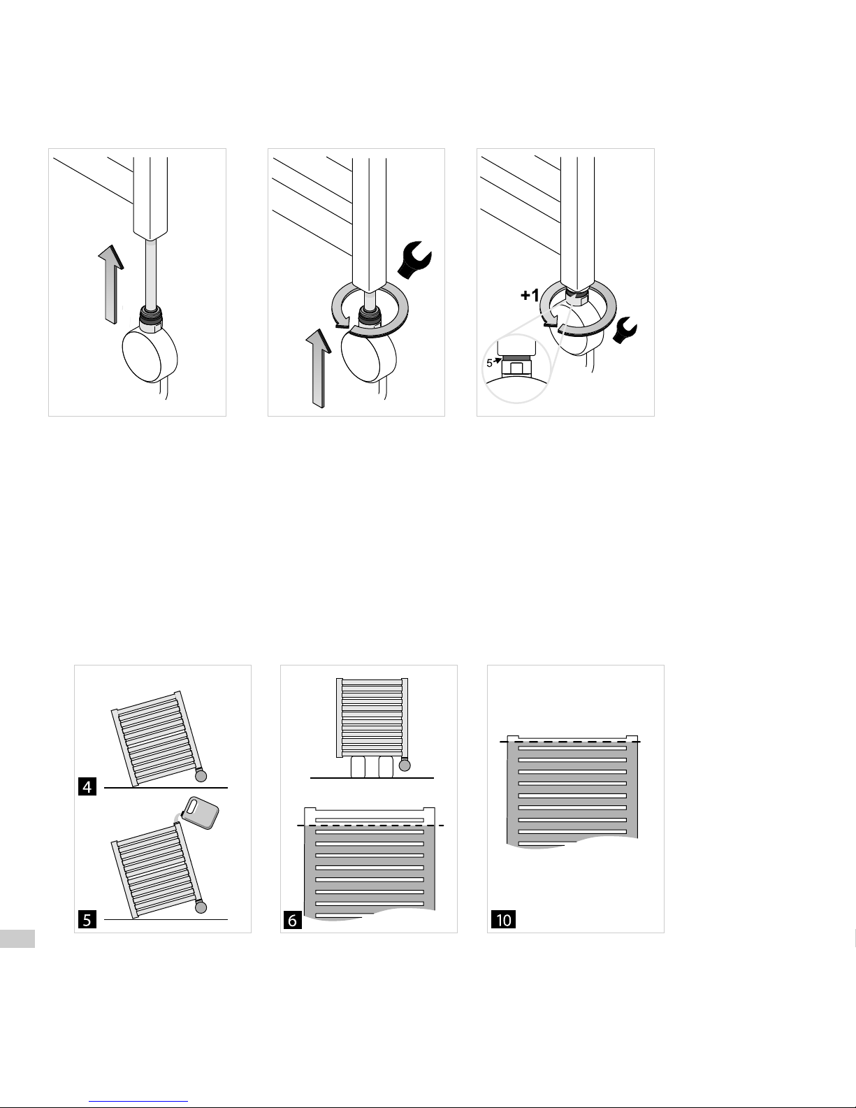
1. Faites glisser la résistance (1) dans le trou fileté au bas du collecteur du radiateur.
2. Serrer la tête du boîtier à l'aide d'une clé plate taille 22.
3. Un joint spécial (5) rend le raccord étanche et permet d'effectuer un tour supplémentaire permettant de bien
possitionner le front du boîtier.
4. Positionner le radiateur obliquement, de sorte que l'entrée soit dans le point le plus haut. !!! Radiateur ne peut
pas s'appuyer contre le boîtier ni contre les éléments de jonction !!!
5. Remplir le radiateur du fluide caloporteur.
6. Redresser le radiateur afin de contôler le niveau du liquide.
7. Assurez-vous si la jonction résistance – radiateur reste étanche.
8. Brancher l'appareil dans la prise et le mettre en marche (orifice supérieur reste ouvert !).
8.1. Il est possible d'utiliser le fluide caloporteur chaud mais non supérieur à 65°C. Dans ce cas, remplir
l'intégralité du radiateur, redresser-le et mettre le kit résistance en marche.
9. Régler le réglage maximal du kit résistance et observer la montée du liquide caloporteur : le surplus du liquide
peut couler via le trou supérieur. Dans ce cas, enlever le surplus du liquide de sorte de ne pas permettre de
mouiller le boîtier.
10. Une fois le liquide cesse d'augmenter son volume, attendre encore 5 minutes et arrêter l'appareil. Ensuite
débrancher-le de la source d'alimentation/prise.
11. Sans attendre le refroidissement du radiateur, enlever une petite quantité du fluide jusqu'au niveau de la motié
de la dernière tube.
12. Fermer l'ouverture supérieure à l'aide du bouchon, accrocher le radiateur.
13. Brancher le kit résistence dans la prise/ source d'aliementation. Appareil est prêt à marcher.
Page 31
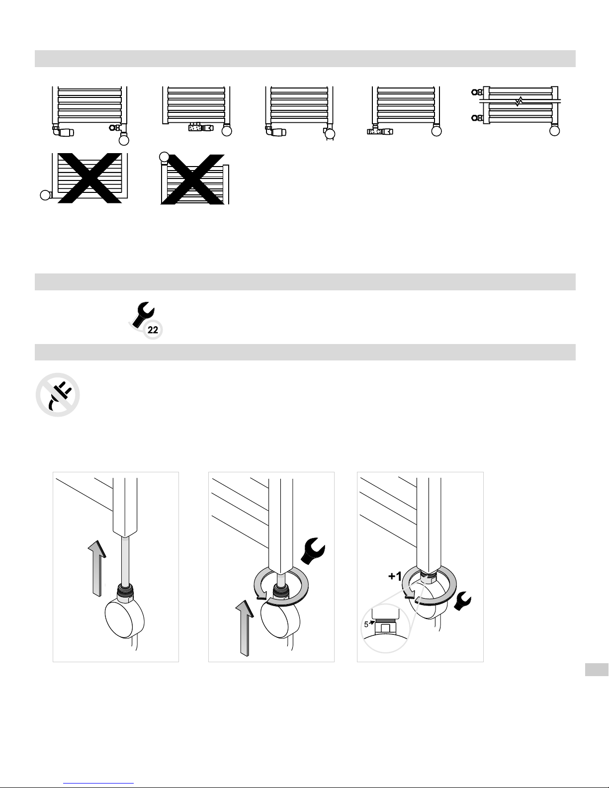
Radiateur MIXTE :
1. Radiateur mixte est un radiateur raccordé à l'installation à eau chaude avec supplément kit résistance monté.
2. Installation doit être équipée des vannes permettant d'arrêter le radiateur.
3. Il est conseillé de purger le radiateur après chaque longue pause dans l'usage du radiateur.
4. Montage résistance vers le bas interdit.
OUTILS NÉCESSAIRES POUR INSTALLER LE KIT RÉSISTANCE
– clé plate taille 22
INSTALLATION DU KIT RÉSISTANCE
ATTENTION ! Lors du montage, l'appareil ne doit pas être sous tension. Retirer la fiche de la prise.
1. Dans le radiateur raccordé à l'installation à eau chaude, fermer les deux vannes et enlever le fluide caloporteur.
2. Faites glisser la résistance (1) dans le trou fileté au bas du collecteur du radiateur.
3. Serrer la tête du boîtier à l'aide d'une clé plate taille 22.
4. Joint spécial (5) rend le raccordement étanche et permet d'effectuer un tour additionel d'appareil afin de
positionner correctement le front du boîtier.
5. Ouvrir les vannes, remplir le radiateur du fluide de l'installation, purger le radiateur.
Page 32
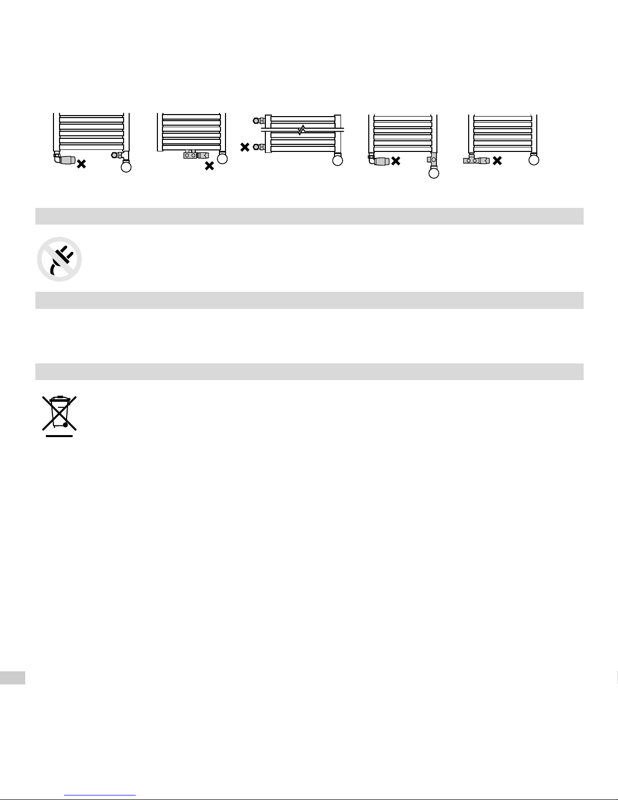
6. Assurez-vous si la jonction résistance – radiateur reste étanche.
7. Avant de mettre en marche le kit résistance, il est conseillé de fermer une et laisser ouverte l'autre vanne ! (il est
conseillé de fermer la vanne avec la tête thermostatique).
Avant chaque mise en marche, assurez-vous si l'une des vannes reste ouvrete !!
8. Brancher le kit résistence dans la prise / source d'aliementation. Appareil est prêt à marcher.
DÉMONTAGE DE L'APPAREIL
1. Dans le radiateur raccordé à l'installation à eau chaude, fermer les vannes et enlever l'eau du
radiateur. Dans le cas du radiateur électrique, retirer-le du mur et positionner de façon de ne pas
laisser couler le fluide caloporteur lors du démontage du kit résistance.
2. Dévisser le kit résistance à l'aide d'une clé plate taille 22.
ENTRETIEN
1. Débrancher l'appareil avant chaque nettoyage.
2. Nettoyer le boîtier avec un tissu propre et sec ou légèrement humide avec peu de détergent, sans solvants et
abrasifs.
RECYCLAGE DE L'APPAREIL
Ne pas jeter l'appareil avec des déchets ménagers. Retourner-le au point de collecte et de recyclage
d'appareils des équipements électriques et électroniques. En informe l'icône sur le produit, sur le
mode d'emploi et sur l'emballage. Demander le vendeur ou contacter le fabricant pour trouver le
point de collecte et de recyclage le plus proche. Merci de contribuer à la protection de
l'enevironnement.
Page 33
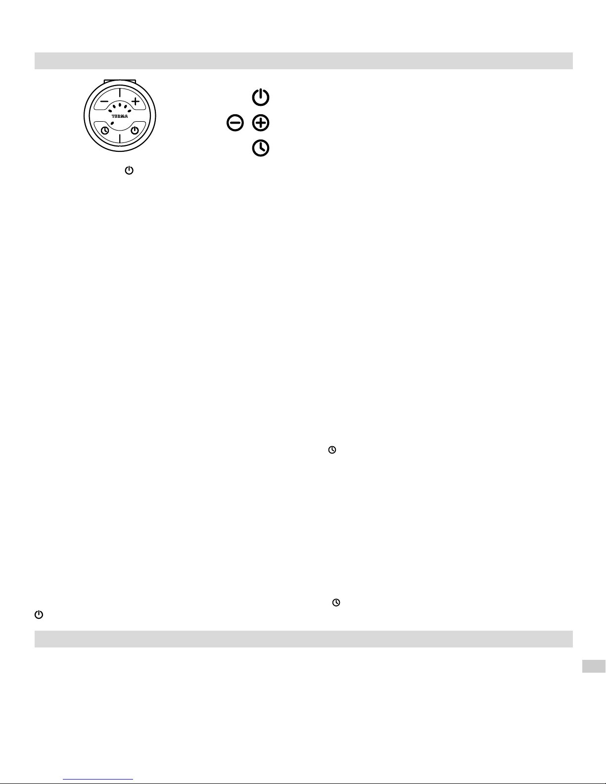
FONCTIONS ET USAGE D'APPAREIL (MODÈLE SOA)
→ marche/arrêt,
→ réglage de la puissance de chauffe
→ marche/arrêt de la fonction marche forcée
Appui de la touche met l'appareil en marche qui rechauffe le radiateur en se mettant en marche et en arrêt en
alternance, tout en maintenant la chauffe dans la plage 30-100% de puissance nominale d'appareil.
La construction d'appareil permet également de limiter la température une fois le radiateur atteint la température
maximale de 60°C.
Construction d'appareil (résistance chauffante PTC) protège contre les brûlures, autolimitant la température du
radiateur à 60°C, quel que soit le réglage actuel (à condition que la puissance de la résistance est correctement
adaptée à la puissance du radiateur).
Construction du kit résistance, ainsi que les propriétés physiques du fluide caloporteur provoquent le fait que les tubes
en bas du radiateur (deux dernières en partculier) peuvent avoir la température diverse par rapport au reste des tubes.
Cet effet est tout à fait naturel.
Réglage de la puissance de chauffe :
Pour le confort thermique désirable, définir le niveau approprié de la puissance de chauffe (touches +/-).
Il est possbile de définir 1 de cinq niveaux de la puissance de chauffe 30-40-60-80-100% de la puissance nominale.
Fonction MARCHE FORCÉE
Fonction MARCHE FORCÉE permet de programmer l'appareil pour qu'ilchauffe pendant 2 heures avec de la
puissance diverse, p.ex. pour sécher une serviette. Deux heures passées, l'appareil se remet en travail d'avant la
mise en marche forcée.
Pour activer la fonction MARCHE FORCÉE, appuyer la touche (possible également quand l'appareil est en arrêt ).
L'appareil se met en marche avec la puissance actuellement réglée. Il est possible de la modifier à tout moment, aussi
durant le travail d'appareil (touches + et -).
Si, avant la mise en marche via cette fonction, l'appareil a été en arrêt, il s'arrêtera automatiquement une fois la
période de deux heures terminée.
Si, avant la mise en marche de la fonction marche forcée, l'appareil était en marche, p.ex. avec du réglage 2, le
réglage de marche forcée a été modifié manuellement vers la réglage p.ex., une fois les deux heures passées,
lappareil reprend le réglage 2.
Attention : L'appareil en marche, fonction marche forcée mise en marche sans modifier son réglage de chauffe, une
fois les deux heures passées il n'y aura aucun changement. L'appareil va chauffer selon le réglage actuel.
Afin d'arrêter la fonction MARCHE FORCÉE, appuyer la touche . Arrêt et la mise en marche d'appareil via la touche
déactive également la fonction marche forcée.
FONCTION ANTI-FREEZE (Hors gel)
Si l'appareil est arrêté et la température dans l'environnement du capteur de température descend au-dessous du
seuil 6°C, l'appareil se mettra automatiquement en marche, afin de proteger le fluide caloporteur contre le gel.
Fonction ANTIFREEZE active, est indiquée par le clignotement de la diode centrale
Page 34
GUIDE DE DÉPANNAGE
Problème Cause probable
Appareil est branché, aucune
diode n'est allumée
Problème du raccordement.
Appareil chauffe malgré la mise
en arrêt via la touche
Partie électronique en panne.
Si le problème se répète, contacter le Vendeur.
Action recommandée
Vérifier le raccordement du câble
d'alimentation et si la tension est correcte.
Débrancher appareil, laisser refroidir,
brancher à nouveau
CONDITIONS DE GARANTIE
1. La garantie concerne le kit résistance fabriqué par Terma Sp. z o.o. Nom du modèle et les caractéristiques sont
indiqués sur l'emballage.
2. Client confirme l'état non défectueux d'appareil à la reception. En cas d'un défaut quelconque, il est obligé d'en
informer le Vendeur. Dans le cas contraire, on estimera que le produit n'a pas été défectueux. Cela concerne en
particulier la surface du boîtier.
3. La période de garantie est de 24 mois à compter de la date d'achat mais pas plus de 36 mois de la date de
fabrication.
4. La base de l'application de garantie est la carte de garantie accompagnée d'une preuve d'achat. Le fabricant se
réserve le droit de refuser l'application de la garantie si ces documents ne sont pas présentés ou sont incomplets..
5. La garantie ne s'applique pas en cas des endommagements causés par:
– montage ou démontage incorrect (non respect des consignes du présent mode d'emploi)
– usage de la résistance chauffante à des buts auxquels elle n'a pas été destinée
– intervention des personnes non autorisées sur le produit
– faute du Client après la réception du produit.
6. Le réseau d'installation doit être équipé des vannes d'arrêt permettant le démontage du radiateur ou du kit
résistance sans vider le fluide caloporteur de toute installation. Problèmes ou coûts causés par l'absence de telles
vannes, ne sont pas pris en charche par Terma.
7. Le mode d'emploi joint fait la partie intégrale de la présente garantie. Il est recommandé d'en prendre
connaissance avant tout usage d'appareil.
8. La fabricant s'engage à rémedier au défaut dans les 14 jours ouvrables à compter de la date de reception à l'usine
du produit endommagé.
9. Si la réparation de l'appareil s'avère impossible, le fabricant s'engage à le remplacer par le produit neuf et
identique.
Page 35

Page 36

MPGKE-89
TERMA Sp z o.o.
Czaple 100, 80-298 Gdańsk, Poland
tel.: +48 / 58 694 05 00, fax: +48 / 58 694 05 06
[email protected]
www.termagroup.pl
 Loading...