

Page 1

CHANGE ORDER/REVISION
CO: REV:
CO: REV:
CO: REV:
CO: REV:
CHKD: CM:
CHKD: CM:
CHKD: CM:
CHKD: CM:
REVISION STATUS OF SHEETS:
SYSTEM DESIGN SPECIFICATION
SHEET NO: All sheets same revision
REVISION:
Surface Movement Radar
CODE: D4
30 SHEETS
INIT RELEASE:
DATE OF THIS ISSUE:
REV: A
PREP: JET
CHKD: -
APVD: JET
CM: LSN
DOCUMENT NO: 256627 DS
SH: 1
System Specification
TERMA SCANTER RADAR
for
Sao Paulo Guarulhos
Dual RxTx SMR system
© TERMA Elektronik AS, DK-8520 Lystrup, Denmark
Page 2

REV: A
PREP: JET
CHKD: -
APVD: JET
CM: LSN
DOCUMENT NO: 256627 DS
SH: 2
Scope
This document specifies the main parameters of TERMA’s SCANTER X-Band Radar Sensor
System for use in the Sao Paulo Guarulhos ASMGCS system.
The system is based on features available as standard in the SCANTER product programme
including a 21” Slotted Wave-guide circular polarised TERMA antenna.
Referenced Documentation
245490 DP Product Specification, SCANTER Service Display.
243522 SI Interface Specification.
244118 SA Functional Specification, Service.
244119 SA Functional Specification, BITE.
240100 ZD Installation Drawing, RxTx Unit
244700 ZD Installation Drawing, ACSw
The product range is in continuous development and TERMA reserves the right to include
additional features within the products and in the referred documents, as they become available.
© TERMA AS, DK-8520 Lystrup, Denmark
Page 3

REV: A
PREP: JET
CHKD: -
APVD: JET
CM: LSN
DOCUMENT NO: 256627 DS
SH: 3
List of Contents
1 INTRODUCTION ........................................................................................................... 5
1.1 General .............................................................................................................................. 5
1.2 Documentation .................................................................................................................. 5
1.3 Deliverables ...................................................................................................................... 6
2 FUNCTIONAL DESCRIPTION ................................................................................... 6
2.1 System Layout ................................................................................................................... 6
2.2 Dual System Configuration ............................................................................................... 6
2.3 RxTx Unit ......................................................................................................................... 7
2.3.1 Frequency of Operation ....................................................................................... 7
2.3.2 Transmitter ........................................................................................................... 8
2.3.3 Receiver ............................................................................................................... 8
2.3.4 Radar Signal Distribution .................................................................................... 9
2.3.5 Antenna Control Interface ................................................................................. 10
2.3.6 Safety Loop ........................................................................................................ 10
2.3.7 Remote Access ................................................................................................... 11
2.3.8 Mains Power Supply .......................................................................................... 11
2.4 Modular Configuration ................................................................................................... 11
2.4.1 Environmental Capabilities, RxTx and ACSw .................................................. 13
2.5 Safety .............................................................................................................................. 13
2.5.1 Safety Switch (Man Aloft) Circuits ................................................................... 13
2.5.2 Interlock and Service Switch ............................................................................. 14
2.5.3 Safety Ground and Shielding ............................................................................. 14
2.5.4 Electrical/Mechanical Safety Aspects ............................................................... 14
2.5.5 EMC/EMI Aspects ............................................................................................. 14
2.5.6 Other Aspects of Approval ................................................................................ 14
2.6 Antenna ........................................................................................................................... 15
2.6.1 Electrical Performance ...................................................................................... 15
2.7 Horizontal Radiation Pattern........................................................................................... 15
2.8 Elevation Patterns ........................................................................................................... 17
2.8.1 Rain Cancellation .............................................................................................. 17
2.8.2 Antenna Motor Status Signals ........................................................................... 17
2.8.3 Environmental Capabilities, Antenna ................................................................ 18
2.9 ACSw Unit ...................................................................................................................... 19
2.10 Remote Control, Remote BITE, Remote Service ........................................................... 19
2.10.1 Service Display .................................................................................................. 19
2.10.2 Remote Control .................................................................................................. 20
2.10.3 Communication .................................................................................................. 20
2.11 RCBS Control Functions ................................................................................................ 20
2.11.1 RxTx Administered Controls ............................................................................. 20
2.11.2 RxTx Administered Alarms ............................................................................... 21
3 FALL BACK MODES .................................................................................................. 22
3.1 Single Point Failures ....................................................................................................... 22
4 FUNCTIONAL CAPABILITIES ................................................................................ 22
4.1 Target Detection .............................................................................................................. 23
4.2 Coverage ......................................................................................................................... 24
4.3 Performance - Resolution ................................................................................................ 26
4.2.1 Performance Calculations .................................................................................. 24
© TERMA AS, DK-8520 Lystrup, Denmark
Page 4

REV: A
PREP: JET
CHKD: -
APVD: JET
CM: LSN
DOCUMENT NO: 256627 DS
SH: 4
5 MECHANICAL CAPABILITIES AND CONSTRAINTS. ...................................... 27
6 AVAILABILITY AND MAINTENANCE. ................................................................. 27
6.1.1 Environment ...................................................................................................... 27
6.1.2 MTBF/MTTR Evaluation .................................................................................. 28
6.1.3 External Bi-Directional Couplers ...................................................................... 29
7 INSTALLATION MATERIAL ................................................................................... 30
Abbreviations & Acronyms
ACP Azimuth Count Pulse
ACSw Antenna Control and Switch Unit
ACU SCANTER Antenna Control Unit
AFC Automatic Frequency Control
ARP Azimuth Reference Pulse
BITE Built-in Test Equipment
BW Bandwidth
FTC Fast Time Constant
HW Hardware
IF Intermediate Frequency
I/O Input/Output
LIN Linear
LNFE Low Noise Front End
LOG Logarithmic
LRU Line Replaceable Unit
MTBF Mean Time Between Failure
MTTR Mean Time To Repair
NF Noise Figure
NF&P Noise Factor & Power
PC Personal Computer
PRF Pulse Repetition Frequency
PRI Pulse Repetition Interval
PW Pulse Width
PWB Printed Wiring Board
RAM Random Access Memory
RCBS Remote Control, BITE, and Service
RCSW Remote Control Software
RCS Radar Cross Section
RF Radio Frequency
RPM Rotation Per Minute
RxTx SCANTER Receiver Transmitter Unit
STC Sensitivity Time Control
SW Software
SWG Slotted Wave Guide
TBD To be defined
WG Wave Guide
WGSw SCANTER Wave Guide Switch
© TERMA AS, DK-8520 Lystrup, Denmark
Page 5

REV: A
PREP: JET
CHKD: -
APVD: JET
CM: LSN
DOCUMENT NO: 256627 DS
SH: 5
Quantity
Description
1 per system
Set of Technical Manuals including:
- Technical descriptions and specifications
- Installation drawings
- Maintenance and fault finding instructions
- Parts list, system, unit and LRU level
- Test instructions
- External interface documentation
1 per system
System Technical Manual including:
- Operation instructions
- Maintenance instructions
- Product specification
- System and Site documentation
- Installation documentation
Operator’s Manual, SCANTER Service Display
Operator’s Manual, Antenna
Set of FAT documentation including:
- Certificate of Conformance
- System FAT test results
- Serialised Assembly Records for all Units
- Warranty Statement
1 INTRODUCTION
1.1 General
The SCANTER Radar Sensor System is designed for safe and reliable operation.
The transmitter, receiver and signal processing technology is designed to ensure optimum
performance of the SCANTER Radar Sensor Systems for continuous operation in all weather
conditions.
1.2 Documentation
The system is to the extent possible configured from features available as standard in the product
programme and documented accordingly.
© TERMA AS, DK-8520 Lystrup, Denmark
Page 6

REV: A
PREP: JET
CHKD: -
APVD: JET
CM: LSN
DOCUMENT NO: 256627 DS
SH: 6
1.3 Deliverables
The project consists of delivering two identical dual X-band radar systems, pre-installed on a
plywood board including 2 RxTx units, one ACSw and a 21” fixed circular polarised antenna.
The ACSw will be able to control the TERMA antenna. The system will also include one Service
Display equipped with a scan converter, a Castell Safety Switch.
The delivery does contain on-site installation materials, including mating connectors for all units
and cabling between the radar system and connected systems/units. TERMA AS will perform
installation, alignment/Setting to Work and commissioning.
2 FUNCTIONAL DESCRIPTION
2.1 System Layout
The concept of the dual system layout is to obtain redundancy, for systems where continuous,
uninterrupted operation is vital.
The configuration includes outputs delivering analogue Trigger, Video and Azimuth both from
the ACSw and from each of the RxTx’s, when active.
Please refer to the System Block Diagram, 256627 EB, for further details.
Safe and reliable operation is of high importance for the application and each individual
SCANTER product is designed bearing that in mind. Components are selected with care and derated to ensure long lifetime, and numerous Fallback modes exist as an integral part of the design.
Redundant systems are furthermore designed to keep any possible single point of failure as
simple as possible.
High antenna gain and Circular Polarisation is required in order to obtain sufficient range
coverage and sufficient rain penetration. The radar return - and thus the requirement to dynamic
range - increases twice as much as additional antenna gain (in dB).
The transmitter frequencies available have been selected to comply with world-wide ITU
regulations for frequency allocation.
The receiver-transmitter unit acts as the central part of the radar system as it performs control of
the communication between the units and generates the basic radar signals.
The units are all equipped with computer-controlled built-in test equipment (BITE). This may be
interrogated from a local Personal Computer (PC) with control and monitoring software. The
recording of BITE messages will store all fault messages when they occurred in a database.
2.2 Dual System Configuration
The system has Fallback possibilities so that each RxTx can operate independently as a normal
single-frequency system in case of any system failures. This means that one channel can be taken
out of service without having an impact on the other channel.
A pilot voltage separately powers the Controller Board in the RxTx unit, maintaining
communication and BITE features, if other parts of the unit become faulty.
Each of the RxTx units can operate independently of the other, controlled manually via the buildin control panel in each RxTx unit or by use of remote controlling features.
© TERMA AS, DK-8520 Lystrup, Denmark
Page 7
REV: A
PREP: JET
CHKD: -
APVD: JET
CM: LSN
DOCUMENT NO: 256627 DS
SH: 7
Control of the antenna is provided via parallel diode protected lines, one from each RxTx,
3 Stage Limiter
Manual STC
Antenna
Transmitter
Load
Circulator
2 Stage low noise Pre-amplifier
Image Rejection Mixer
Local Oscillator
1. Stage IF and BW filter
Logarithmic IF
and Envelope
Detector
Radar Signal Distribution
4096 ACP+ 1 ARP
3 x Trigger
3 x Video
3 x Azimuth
Basic System
maintaining operation if one of the RxTx becomes faulty.
2.3 RxTx Unit
The unit comprises a complete X-band Surveillance Radar Transmitter and Receiver in a selfcontained shielded enclosure.
The RxTx unit delivers three sets of analogue radar signals, video, trigger and azimuth, and two
serial channels for remote control of the radar system.
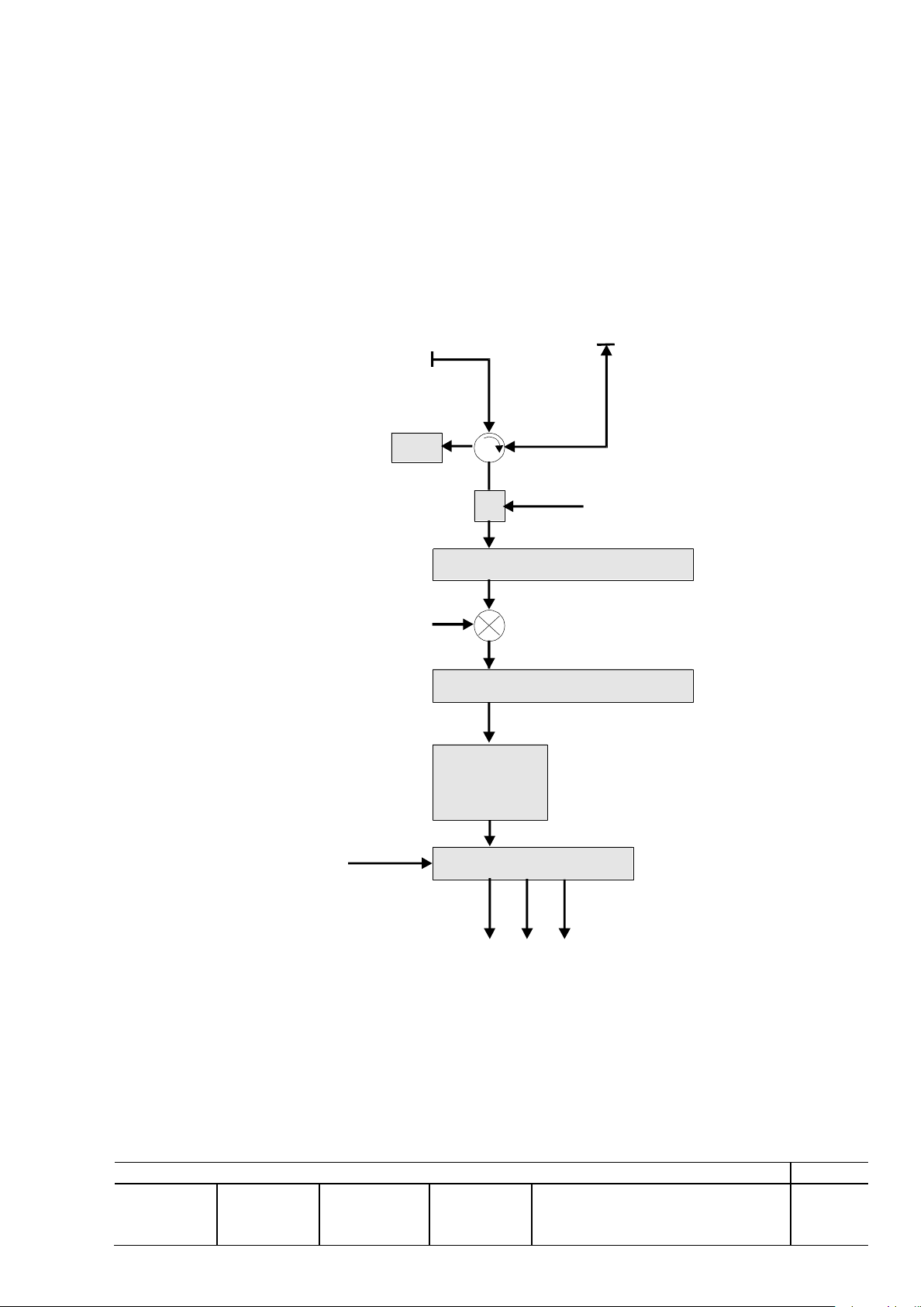
The video/signal path configuration in the RxTx unit is as shown in Figure 2.3-1 RxTx Signal
Path below.
2.3.1 Frequency of Operation
RF centre frequency: Dual
RxTx 1: 9375 ±30 MHz
RxTx 2: 9375 ±30 MHz
Figure 2.3-1 RxTx Signal Path
© TERMA AS, DK-8520 Lystrup, Denmark
Page 8

REV: A
PREP: JET
CHKD: -
APVD: JET
CM: LSN
DOCUMENT NO: 256627 DS
SH: 8
2.3.2 Transmitter
Peak RF power output:
Magnetron output: 25-30 kW nominal
at RX-TX output flange: 17 kW +10/-2 kW
pulse width measured at half power:
at 3 dB (70 % points): 40 ns ±10%
at 6 dB (50% points): 50 ns ±10%.
PRF:
Programmable range excl. stagger: 798-8068 Hz nominal
(5-8 kHz is normal for operation)
Set-up values: PRF = 25 104/K; 31K313
Max operational tolerance: ±2% (without stagger)
Pseudo random stagger: 0% No staggering
2% +1.5% to 2% in 8 steps
4% +3% to 4% in 8 steps
8% +6% to 8% in 8 steps.
2.3.3 Receiver
Noise factor measured between the RxTx RF input port and an IF output placed after the mixer
and any IF pre-amplification.
The receiver provides only logarithmic video on the output.
The typical and LNFE noise factors are stated for comparison only.
Overall: 4.7 dB
Overall, typical: 4.0 dB
Corresponding to LNFE: 2.5 dB.
Tuning:
Electronic tune in respect to
coarse tune setting: ±50 MHz
AFC locking range: ±25 MHz
Swept gain (STC) is applied at RF with range characteristics as per pre-defined curve or as
programmed by use of the RCBS tool:
Range: 0 to 5000 metres
Attenuation: Up to 45 dB
Range resolution: 50 metres/STC cell
Smoothing: 1st order filter
Programming characteristics: Programmable current generator, 0-4 mA, cor-
responding to 0-50 dB nominal attenuation,
8 bit resolution.
Overall dynamic range: >95 dB incl. swept gain (STC).
IF:
Centre frequency: 100 MHz nominal
Bandwidth (3 dB): 50 ±4 MHz
Filter characteristics: Single-pole Gaussian
Spurious emissions (0.1-4100 MHz): < 45 dBm.
© TERMA AS, DK-8520 Lystrup, Denmark
Page 9

REV: A
PREP: JET
CHKD: -
APVD: JET
CM: LSN
DOCUMENT NO: 256627 DS
SH: 9
Logarithmic IF:
Peak amplitude: 5 0.5 V
Log law slope: 10 dB/V
Log law accuracy: Better than ±1 dB (temperature variation incl.)
Noise level, unprocessed video: 0.25 0.15 V RMS
DC level: < 0.5 V (0-70C)
0.2 0.1 V (15-35C).
Local Oscillator Leakage at RF port: < 30 dBm.
2.3.4 Radar Signal Distribution
The encoder used will provide 4096 ACP pulses per revolution.
Video output signals (DC coupled analogue outputs):
Number of outputs: 3, open and short circuit protected
Level: 0 to +5 V ±1 V
DC level: <0.5 V DC
Drive capacity: 75 nominal load
Video bandwidth: 40 MHz (raw video)
a. Trigger outputs:
Number of outputs: 3, open and short circuit protected, each pro-
grammable to supply t0, PPI, or pre-trigger
Functionality: Trigger point at low-to-high transition
Amplitude: +8 ±1 V
Drive capacity: 75 nominal load
Pulse width: >1.0 s
Rise time: <180 ns (10-90%).
b. Azimuth Count Pulse (ACP)/Azimuth Reference Pulse (ARP) input:
Rotation rate: 60 rpm ±10%
Pulses per revolution: 4096 ACPs plus 1 ARP
Duty cycle: 50 ±10%
Format: 2 balanced line, RS-422
Differential level: 0.5 to 7 V (high); 0.5 to 7 V (low)
Source drive capability: 130 nominal, centre ground
Common mode voltage: 18 V to +18 V allowed.
c. Azimuth count pulse output:
Number of outputs: 3, open and short circuit protected
Pulses per revolution: 4096 ACPs plus 1 ARP
Pulse widths: ACP 10 µs
ARP 10 µs but less than ACP pulse width
Format 3 balanced line, RS-422
© TERMA AS, DK-8520 Lystrup, Denmark
Page 10

REV: A
PREP: JET
CHKD: -
APVD: JET
CM: LSN
DOCUMENT NO: 256627 DS
SH: 10
Differential level: Compatible with RS-422 receiver
2.4 to 5.5 V (high); 2.4 to 5.5 V (low)
Drive capability: 130 nominal
Antenna correction: 0 to 359.9° in steps of 0.1°
Azimuth signals are not compensated to north in order to ensure optimum accuracy and to allow
for use of both positive and negative-going edges in the connected equipment. Compensation to
north shall therefore be made in both the connected equipment.
d. Sector transmission:
Sector bearing: 0-359°
Sector width: 10-350°
Resolution: 1°.
The defined sector is the transmitting part of the rotation.
2.3.5 Antenna Control Interface
a. Antenna control output:
Format: Relay drive
Functionality: Open: Stop motor. +26 V: Start motor
Number of outputs: 1 (parallel coupling allowed).
b. Antenna fault alarm:
Mechanism: Open/closed contacts, 20 mA current loop
Functionality:
Normal operation: Closed contact: Enables motor supplies and
allows RF transmission
Fault: Open contact: Disables motor supplies and
RF transmission
Number of inputs: 1 (with diode to allow for parallel coupling)
Contact rating: Minimum 30 V DC, 50 mA.
c. Auxiliary inputs:
Format: 20 mA current loop for external contacts
Level: Floating
Contact rating: Minimum 30 V DC, 50 mA
Number of inputs: 2.
d. Auxiliary outputs:
Number of outputs: 2
Format: Relay contact
Level: Floating
Contact rating: 100 V, 1.0 A DC, 50 VA max.
2.3.6 Safety Loop
The safety loops are for connection to one or more external safety (or man aloft) switches. Series
coupling of numerous clean contact sets is allowed.
© TERMA AS, DK-8520 Lystrup, Denmark
Page 11

REV: A
PREP: JET
CHKD: -
APVD: JET
CM: LSN
DOCUMENT NO: 256627 DS
SH: 11
Format: 2 mA current loop for external contact
Level (external contact): Floating
Functionality: Closed contact: Normal operation
Open contact: Stop motor and RF transmission
Loop resistance: Maximum 100 for normal operation
Number of connections per RxTx: 1.
2.3.7 Remote Access
Data communication lines are available for control and remote service as well as for interfaces to
other units within the system.
Number of lines: 3 (2 for external use)
Functionality/protocol: Based upon 243522 SI
Interface level: EIA standard RS-422 A
Speed: 1200/2400/4800/9600 baud (9600 preferred)
Data word: 1 start bit (low), 8 data bits (LSB first), even
parity, 1 stop bit (high).
Remote Control and, BITE and Service features are defined per functional specifications
244118 SA and 244119 SA.
Recording of BITE messages will store the 10 most recent fault messages and the elapsed time
when they occurred in a data base. These messages will be accessible whenever communication
with a remote site is established, meaning that there is no requirement for permanent connections.
2.3.8 Mains Power Supply
Supply and load characteristics, each RxTx:
Voltage: 230 V AC ±10%
Frequency: 47-63 Hz
Power: 420 VA
Power factor: Cos >0.90 (operational).
Supply and load characteristics, ACSw Unit (Incl. antenna-motor):
Voltage: 3 x 400 V AC ±10%
Frequency: 47-63 Hz
Power: 2,2 kW max.
In case of mains failure the Radar system will restart itself to the operational performance level
prior to the mains failure or forced interruption. The last known operational mode is always
stored in memory and will be entered automatically after power ON.
2.4 Modular Configuration
The SCANTER RxTx unit’s type 240100-xxx for stationary applications comprises a complete
Surveillance Radar Transmitter and Receiver in a self-contained enclosure. For general details
refer to 240100 DP, Product Specification, SCANTER RxTx for Stationary Applications.
The transmitter frequency has been selected to 9.375 GHz for the systems. In order to effectively
eliminate interference from other radars working on the same frequencies (or within the same
frequency band), PRF staggering is provided.
The system is able to deliver three sets of analogue radar signals, trigger, analogue video and
digital azimuth, to external equipment. One set is used for the Service Display.
© TERMA AS, DK-8520 Lystrup, Denmark
Page 12
REV: A
PREP: JET
CHKD: -
APVD: JET
CM: LSN
DOCUMENT NO: 256627 DS
SH: 12
Each RxTx unit is further capable to deliver 8-bit digital video for the extractor connected to each
Radar Location:
Sao Paulo Guarulhos
Antenna
Type TERMA 21" Circular Polarised SWG Antenna
+5V supply for Dual RS422 azimuth encoder (differential 5V output) 4096ACP/revolution
ACSw
Type 244700-008, conf. with
U1 Frequency Converter 1 x 230 V, 2,2 kW max.
Z1 Filter 1 phase
A2 Relay Assy
A3 Blower Assy
RxTx Unit #1 RxTx Unit #2
Type 240100-204, configured with Type 240100-204 configured with
V1 Magnetron 9375 MHz, 25 kW V1 Magnetron 9375 MHz, 25 kW
Power reduction 4 kW to 1.5 kW Power reduction 4 kW to 1.5 kW
A1 Integrated LNFE Preparred for NF&P A1 Integrated LNFE Preparred for NF&P
A2 Direct Drive Modulator 4 kW A2 Direct Drive Modulator 4 kW
A2 Magnetic Modulator 600 nS A2 Magnetic Modulator 600 nS
A3 Pulse Analyser A3 Pulse Analyser
A4 Magnetic Modulator 40(50) nS A4 Magnetic Modulator 40(50) nS
A5 Transformer, Isol. 230/250 V A5 Transformer, Isol. 230/250 V
A12 NF & P Meter A12 NF & P Meter
A13 Internal Interface Type 2 A13 Internal Interface Type 2
A14 Video Processor Type 1 on Lin A14 Video Processor Type 1 on Lin
A14/15 Diversity Controller Type 1 for SWG A14/15 Diversity Controller Type 1 for SWG
A15 Diversity Controller Type 2 for parabollic A15 Diversity Controller Type 2 for parabollic
A15 Video Band Comp. With NAP 21 intf. A15 Video Band Comp. With NAP 21 intf.
A15 Video Processor Type 1 on Log A15 Video Processor Type 1 on Log
A15/16 Video Processor Type 2 on Log A15/16 Video Processor Type 2 on Log
A17 Radar Signal Dist. A17 Radar Signal Dist.
A18 ASC A18 ASC
A19 Radar Status A19 Radar Status
A20 Timing A20 Timing
A21 Controller A21 Controller
A22 Antenna Interface Type 2 A22 Antenna Interface Type 2
A23 Power, DC/DC2 A23 Power, DC/DC2
A24 Power, DC/DC1 A24 Power, DC/DC1
A25 Power, AC/DC A25 Power, AC/DC
A27 Antenna Interface Type 1 A27 Antenna Interface Type 1
Scanter Service Display
Type 245490-011, configured with
English Keyboard
17'' Monitor
Scan Converter
Interface Status Signals
CMPT
channel.
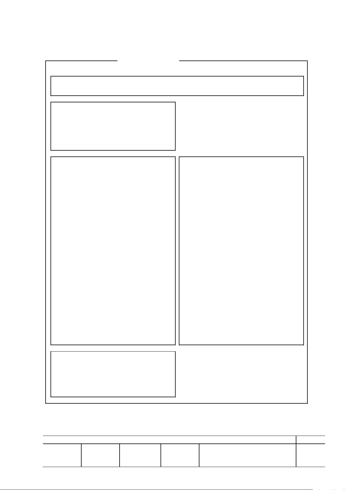
The modular configuration of the system is shown in Figure 2.4-1 System Configuration.
Figure 2.4-1 System Configuration
© TERMA AS, DK-8520 Lystrup, Denmark
Page 13

REV: A
PREP: JET
CHKD: -
APVD: JET
CM: LSN
DOCUMENT NO: 256627 DS
SH: 13
2.4.1 Environmental Capabilities, RxTx and ACSw
Test
Condition
Limit
Corresponding standard
Cold
Storage:
0°C
IEC 68-2-l, Test Ad.
Function:
0°C
IEC 945
Dry Heat
Storage:
+70°C
IEC 68-2-2 Bd.
Function:
+55°C
IEC 945
Protection
Function:
IP 52
IEC 529
Relative
Humidity
Function
10% - 90%
Airborne
Noise
Noise level:
55 dB (A)
DS/ISO 3743 or 3746
Reference level:
1 pW
IEC 945
Bump
Packed for transp.
Peak acceleration:
10g, 16 ms
IEC 68-2-29 test Eb
No of bumps:
1000
EMC
Function:
IEC 945
MIL-STD-461
EN 60945/A1
EN 50081-1
EN 50082-1
Safety
Function
EN 60950/IEC 950.
RxTx unit and Antenna Control Units have been verified to military and civil standards by
accredited test institutes.
The equipment, incl. RxTx type 240100 is further developed on the former basis, and capabilities
are maintained or reinforced in all aspects except for shock and vibration.
Verification is made as comparison tests, evaluations, and calculations against units of the former
generation.
Corresponding test standards are mentioned for reference only (previous tests are underlined).
Degradation is not allowed as a result of exposure to the conditions listed.
2.5 Safety
The SCANTER units covered by this specification are designed to meet UL, CSA, and EU safety
standards. Isolation distances, protective earth, and primary power components are selected to
comply with these, and the major safety measures additionally consist of:
2.5.1 Safety Switch (Man Aloft) Circuits
The safety switch arrangements consist of a current-loop arrangement which, in the event of
activation, will
- remove power from the antenna motor
- remove high voltages from the transmitter to stop transmission.
© TERMA AS, DK-8520 Lystrup, Denmark
Page 14

REV: A
PREP: JET
CHKD: -
APVD: JET
CM: LSN
DOCUMENT NO: 256627 DS
SH: 14
The state of the safety circuit is monitored by the BITE.
2.5.2 Interlock and Service Switch
The RxTx units are equipped with an interlock switch, which will remove high voltages, and
thereby stop transmission if the cabinet is opened. The switch can be manually overruled, but will
automatically be reset when the door is closed.
Furthermore, the units are equipped with external service switches.
All power circuits are discharged to safe values (<30 V) within 2 seconds from removal of power.
2.5.3 Safety Ground and Shielding
All metal parts, incl. cabinet doors, are connected in accordance with IEC 950, and all units are
equipped with grounding studs.
All cabinets must be connected to protective earth as part of any on-site installation.
All installation cables are recommended to be of shielded or double-shielded type with the (outer)
shield connected to chassis at both ends to facilitate optimum safety, EMC protection, and
lightning protection. TERMA shall be consulted if such measures are not possible due to the
danger of corrosion.
2.5.4 Electrical/Mechanical Safety Aspects
For all items of the system EU regulations applies (CE marked).
2.5.5 EMC/EMI Aspects
For all items of the system EU regulations applies (CE marked).
2.5.6 Other Aspects of Approval
None
© TERMA AS, DK-8520 Lystrup, Denmark
Page 15
REV: A
PREP: JET
CHKD: -
APVD: JET
CM: LSN
DOCUMENT NO: 256627 DS
SH: 15
2.6 Antenna
TERMA SCANTER 21' SWG ANTENNA
Antenna Type SCANTER
21' CP - F
MAIN PARAMETERS
Polarisation
Fixed circular
Frequency Band
9140 - 9470 MHz
Gain
37 dBi
Integrated Cancellation Ratio
15 dBi
AZIMUTH PATTERN
Horisontal BW @ - 3 dB
0.37
o
Side lobe level at +/-1.5
o
-28 dB
Side lobe level from +/-1.5o to
+/- 5o, linearly increasing to
-30 dB
Side lobe level from +/-5o to +/10o, linearly increasing to
-35 dB
ELEVATION PATTERN
Elevation Beamform
Fan
Vertical BW @ - 3 dB
11o
Coverage to min., @ -30dB
"-20o
Tilt (Fixed)
-1.5o
TURNTABLE
Motor
2.2 KW, 3 phase
Nominal rotation speed
60 RPM
Bulld in sensors, standard
Motor protection
Option
Motor, high temp. warning
Option
Low oil level warning
Azimuth encoder(s)
2 * 4096 pulses
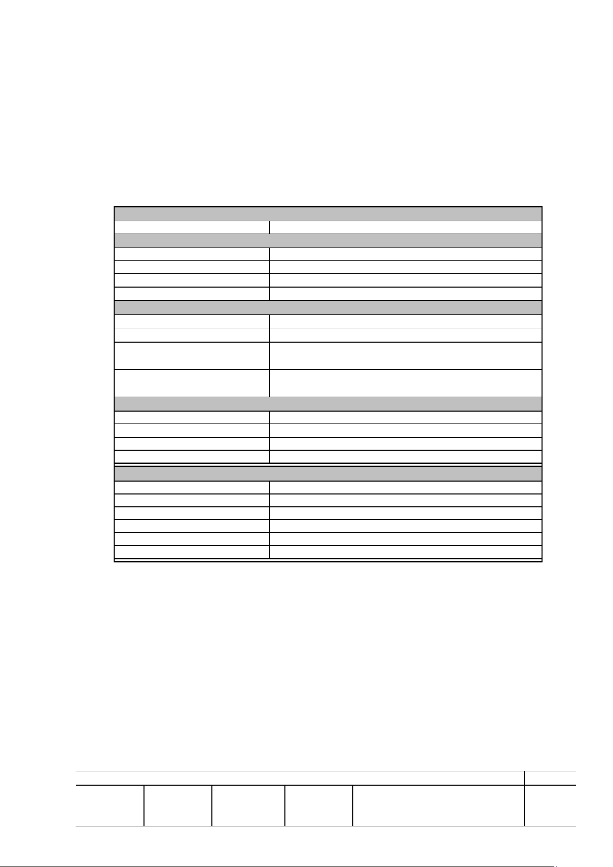
The circularly polarized (CP) antenna is ideal for stationary surveillance applications such as
airport surveillance. The antenna is intended for applications where the traditional radar’s are
limited with respect to performance, tactical requirements, and tough environment such as rain
and snow. These demanding applications require: High Gain (long range), narrow beam-width in
horizontal plane (resolution), low sidelobe levels, low cross polarisation ratios and an axial ratio
near unity within the main beam.
2.6.1 Electrical Performance
xxx
2.7 Horizontal Radiation Pattern
SMR applications will typically, at any fixed point in range and assuming swept gain on RF,
utilise the main beam from its -3 dB to its -20 dB points in order to simultaneously present
runway lights and aircraft’s in any size up to B747’s. Corresponding RCS is ranging from 0.5 m2
to 1.000 m2. Buildings and other fixed structures may be orders of magnitude larger in terms of
RCS, especially those far from the runways etc., and it’s therefore important to have low far
(typically outside +/- 10 or more) side lobes – below -35 dB according to experience.
In total this gives the horizontal radiation pattern, optimised for low far sidelobe levels and
overall shaping of the beam.
© TERMA AS, DK-8520 Lystrup, Denmark
Page 16
REV: A
PREP: JET
CHKD: -
APVD: JET
CM: LSN
DOCUMENT NO: 256627 DS
SH: 16
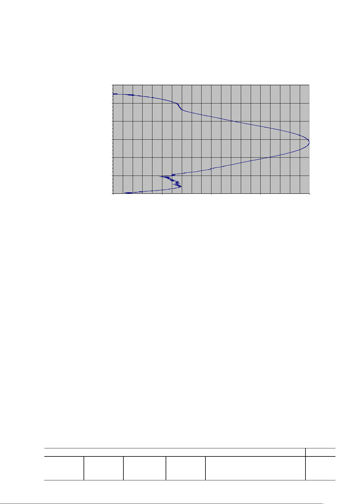
It has furthermore been found that the antenna can be focussed from 1000 meters and onwards to
21' CP-F Antenna - Azimuth Pattern
-40
-35
-30
-25
-20
-15
-10
-5
0
-15 -10 -5 0 5 10 15
Azimuth Angle [deg]
[dB]
Azimuth beamwidth: 0.32 deg
Measured value 0.35 deg Compensation for near field -0.03 deg
Serial no.:
3018
Date: 2. November 2000
Frequency: 9.375 GHz
provide optimum azimuth resolution.
The – 3dB point is often used as the main key parameter in antenna specifications. However, in
practice achieving good overall shape and low far side lobe levels is equally important.
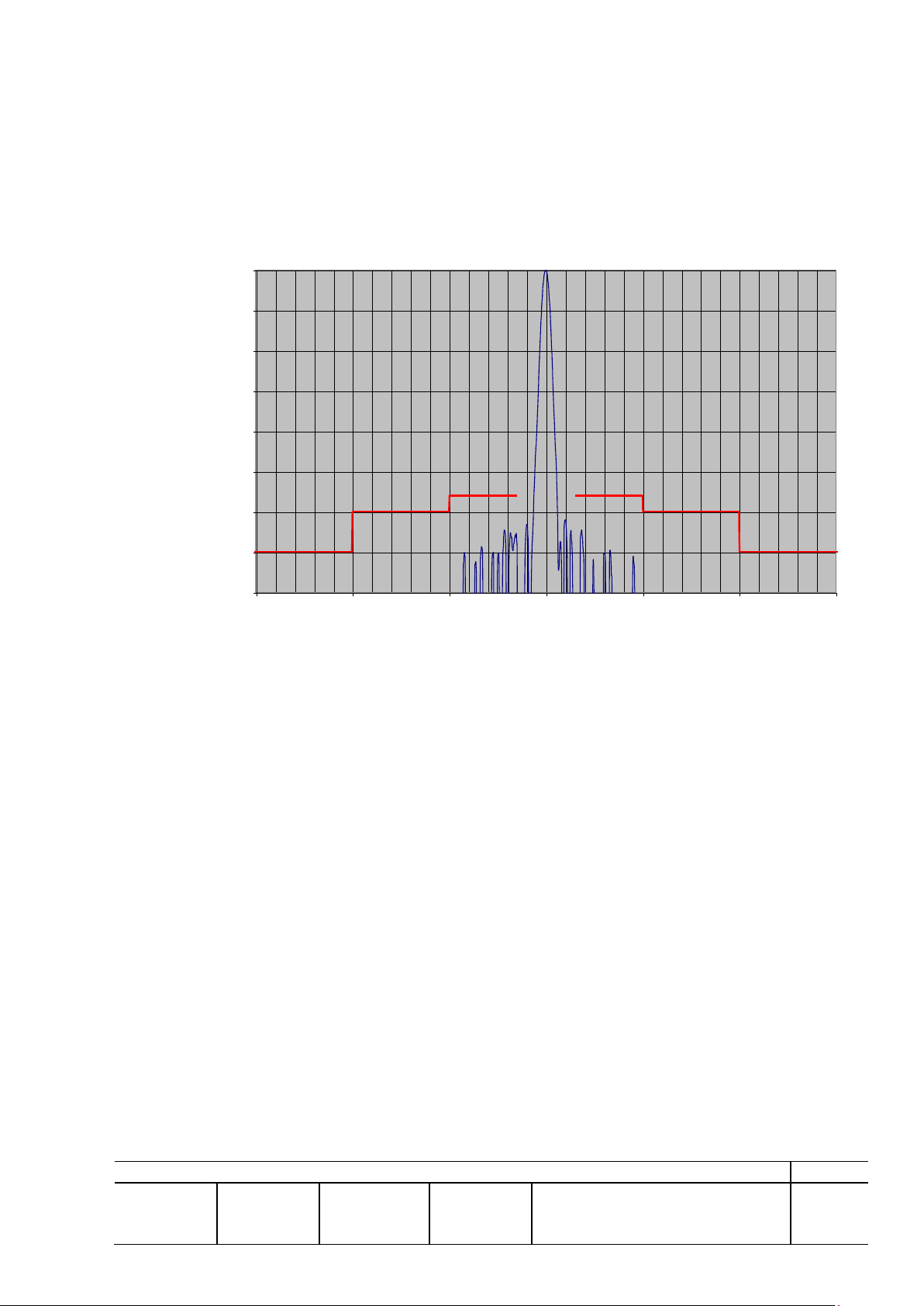
Requirements to all intended applications are virtually identical. Thus, the horizontal radiation
(Azimuth) pattern is shaped as measured in Figure 2.7-1.
Figure 2.7-1: Measured Horizontal Radiation (Azimuth) pattern and specification limits
© TERMA AS, DK-8520 Lystrup, Denmark
Page 17
REV: A
PREP: JET
CHKD: -
APVD: JET
CM: LSN
DOCUMENT NO: 256627 DS
SH: 17
2.8 Elevation Patterns
21' CP-F Antenna - Elevation Pattern
-30
-20
-10
0
10
20
30
-40 -30 -20 -10 0
[dB]
Elevation Angle [deg]
Elevation beamwidth: 9.80 deg
Serial no.:
3018
Date: 2. November 2000
Frequency: 9.375 GHz
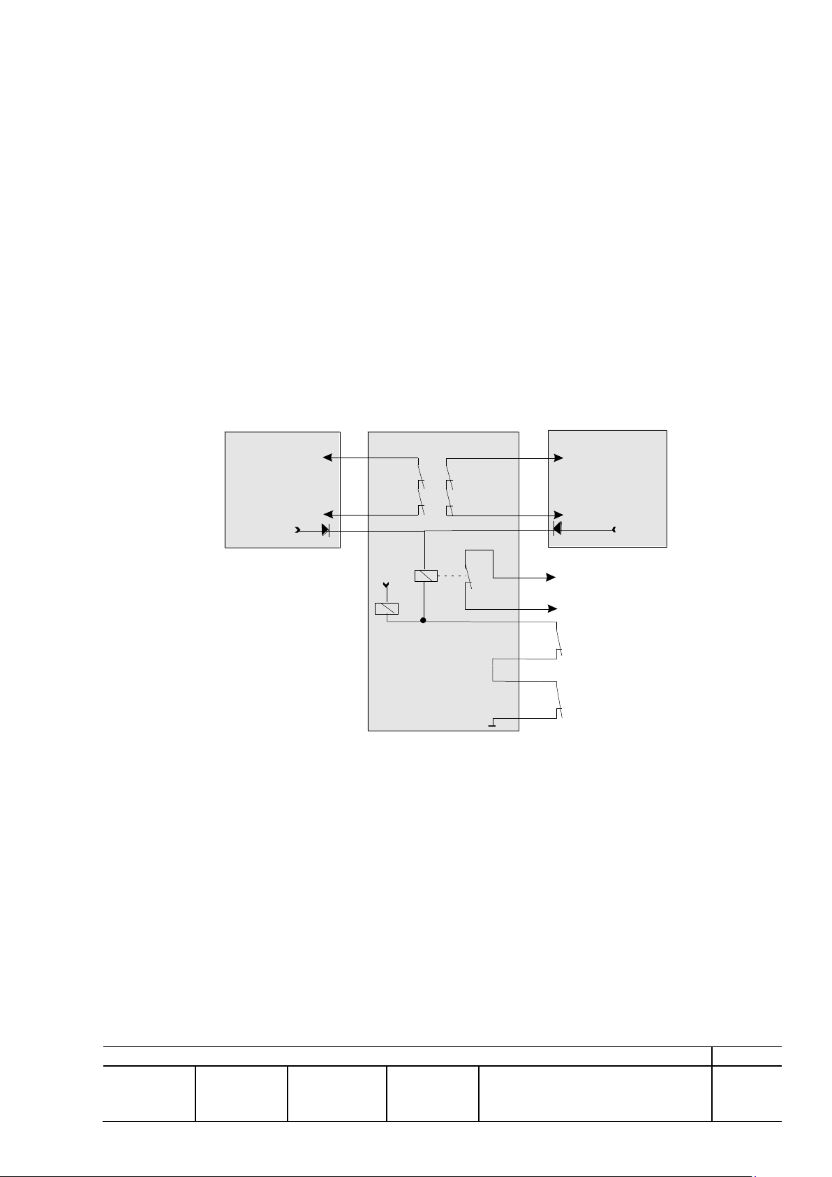
The Fan Beam antennas elevation patterns are optimised for maximum gain and without
significant nulls for coverage to - 20 as illustrated in Figure 2.8-1
Figure 2.8-1. Measured elevation pattern, Fan beam
2.8.1 Rain Cancellation
Circular polarisation is the most efficient tool against disturbance from rain. The efficiency of the
rain cancellation is determined by the antenna Integrated Cancellation Ratio (ICR), close range
surface reflectivity and the shape of the raindrops.
The cancellation at long range is entirely dependent on the ICR and the shape of the raindrops,
where perfect match (e.g. spherical raindrops combined with perfect circularity) would cancel
backscatter from rain completely out of the radar signal. However, raindrops are not perfect
spheres and it is in practice limiting the suppression of rain.
At shorter ranges there is a further limitation because of indirect rays bouncing of the ground and
reflected by rain – twisted 180 in phase - and thereby reducing the effect of circular polarisation
2.8.2 Antenna Motor Status Signals
by a few dB at short range – all depending on the surface reflectivity.
The RxTx units provide input for the following signals from the antenna motor.
For all signals closed contact = No alarm.
System Alarms (Antenna): Motor Temperature and Gearbox Oil Level
© TERMA AS, DK-8520 Lystrup, Denmark
Page 18

REV: A
PREP: JET
CHKD: -
APVD: JET
CM: LSN
DOCUMENT NO: 256627 DS
SH: 18
The motor temperature is in fact monitored by two sensors build into the motor. The first one will
Test
Condition
Limit
Corresponding
Standard
Cold
Storage
40C
IEC 68-2-1, test Ad.
Function
40C
IEC 945
Dry heat
Storage
+70C
IEC 68-2-2, test Bd.
Function
+55C
IEC 945
Protection
Function
IP55
IEC Publication 529
Bump
Packed for transport.
Peak acceleration
10 g in 16 ms
SIEC 68-2-29 test Eb.
No of bumps
1000
Shock
Function
30 g, 11 ms, half sine
IEC 68-2-27
Vibration
Function
4-12.5 Hz: 1.6 mm
12.5-80 Hz: 1 g
IEC 68-2-6 test Fc.
Humidity
Non-operating
60-100% RH
MIL-STD-810E,
method 507.3
Corrosive
atmosphere
Non-operating
35C
MIL-STD-810E,
method 509.3
Rain
Non-operating
Operating
1600 mm/h
60mm/hr
DEF STAN 07-55,
test D3
Hail
Operating
10 mm diameter at 18
m/s
Wind
Operation (60RPM)
Non-Operation
35 m/s
70 m/s
Snow load
Operating
200kg/m2
Ice
The construction will by itself break up to 20 mm built-up clear ice
during start up.
issue a warning when the motor temperature exceeds 130deg and the second one forced the
motor to stop and the transmission as well, when the temperature exceeds 150 deg.
Transmission and turning motor will be restored automatically when the temperature has
decreased sufficiently.
These faults will be reported as Auxiliary input faults detected by the antenna interface board.
2.8.3 Environmental Capabilities, Antenna
The antenna is designed for use in any climate including salt and dust-laden atmosphere, and
must as a minimum be able to withstand the following conditions:
Figure 2.8-2 Environmental Parameters, Antenna
© TERMA AS, DK-8520 Lystrup, Denmark
Page 19
REV: A
PREP: JET
CHKD: -
APVD: JET
CM: LSN
DOCUMENT NO: 256627 DS
SH: 19
2.9 ACSw Unit
Safety Loop
Tx inhibit when OPEN
Antenna ON (26V)
RxTx Unit
ACSw Unit
Antenna Start
for Frequency Converter
26V DC
Antenna Fault
(Temperature)
Castell Safety
Switch
K1
Internal Safety
Switch
K2
K2
K1
Safety Loop
Tx inhibit when OPEN
Antenna ON (26V)
RxTx Unit
K2
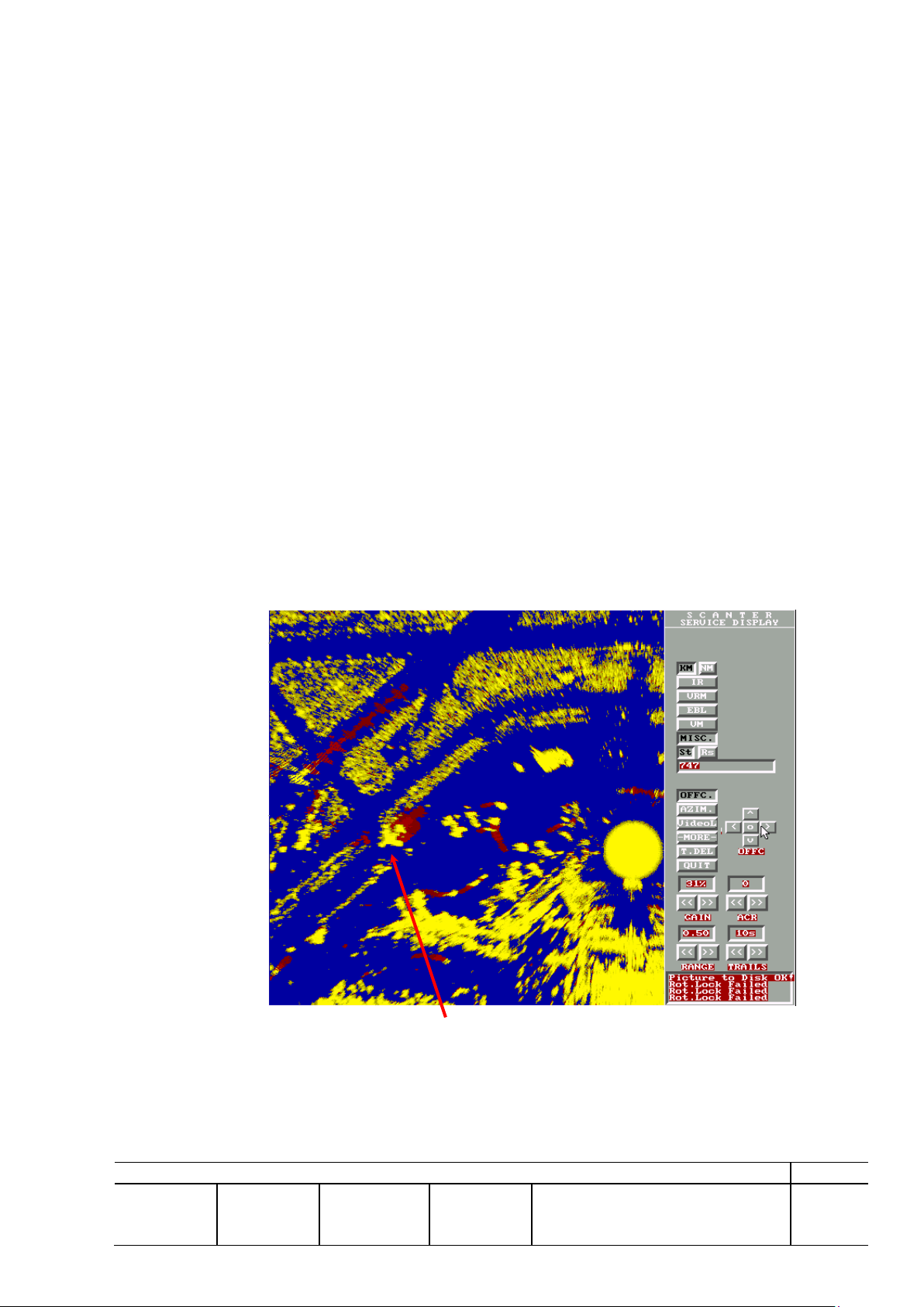
The main circuits for control of the antenna are situated in the ACSw. The control signal flow is
performed from a module built into the RxTx Unit.
- Additionally, the ACSw includes two safety systems being the motor protection
(temperature) and the Internal Safety:
- Activation of the motor protection will cause the antenna to stop and the RxTx to stop
transmitting (stand by mode).
- Activation of the Internal safety rotary switch placed on the front of the ACSw causes the
antenna to stop and the RxTx to stop transmitting (stand by mode) via a current loop.
The ACSw unit provides further the means to connect the external Castell Safety switch system
in series with the Internal switch described above with similar functionality to the system.
The ACSw is controlled and powered from the RxTx units in redundancy with exception of the
supply for the frequency converter, which is supplied direct from the mains distribution board.
Refer to 244700 DP, Product Specification, ACSw, for further details.
2.10 Remote Control, Remote BITE, Remote Service
2.10.1 Service Display
The PC based SCANTER Service Display provides all necessary features for set-up and
maintenance of the SCANTER Radar Sensor Systems including three main functions:
Figure 2.9-1 ACSw and System Interfaces
- Display of a clear, crisp scan-converted radar picture with an overlay of measurement tools
(EBL, VRM, and measurement vector)
- RCBS as described below for remote control and monitoring of the RxTx system.
© TERMA AS, DK-8520 Lystrup, Denmark
Page 20

REV: A
PREP: JET
CHKD: -
APVD: JET
CM: LSN
DOCUMENT NO: 256627 DS
SH: 20
- Tool for programming of swept gain. (STC)
Mains Control (On/Off)
Mains ON:
Switches on the Radar System, and warming up the
transmitter.
Mains OFF
Switches off the Radar System including the
transmitter and the Antenna Motor. All Radar
Controls and Alarms except the Mains ON control are
dimmed (i.e. disabled).
Transmission Control (TX On/Off
TX ON:
Starts RF Transmission, when RF transmission
system is warm.
TX OFF:
Sets RF Transmission on Stand By, i.e. no RF is
transmitted, but system is ready for immediate switch
to TX ON.
The service display is based on a high-end personal computer with minimum a Pentium
processor, colour monitor, the necessary HW interfaces, SW modules, user documentation, and
one set of back up SW on diskette.
2.10.2 Remote Control
Interface to other systems generally uses industry standard trigger, video, azimuth, and RS-422
data formats. In general, remote control of the RxTx and antenna is provided by means of serial
RS-422 communication channels.
2.10.3 Communication
The communication path is dual redundant, and in case of communication loss on the line
between the transceivers, is access to the failed channel still be possible through the left
operational channel and thereby maintaining full accessibility.
Messages for RxTx#2 can be addressed through from RxTx#1 and similar can be stated for
RxTx#1 addressed from/through RxTx #2.
This means that in case of a communication beak down on one channel will full remote access
still be possible through the other channel, if the wiring is changed accordingly.
All communication fall back modes are entered automatically when communication loss is
encountered. The communication fallback modes have no influence on the video path and the
radar system will continue operating in the last known mode.
All communications lines will operate in parallel which means that no one is master. Access to
the system can with this configuration take place from three remote locations at the same time
without any mutual control. All external communication lines can however be switched off by
use of a Service Menu, Local Mode, which can be useful in a maintenance situation. With this
function is no remote control possible.
2.11 RCBS Control Functions
2.11.1 RxTx Administered Controls
© TERMA AS, DK-8520 Lystrup, Denmark
Page 21

REV: A
PREP: JET
CHKD: -
APVD: JET
CM: LSN
DOCUMENT NO: 256627 DS
SH: 21
Antenna Motor control
Motor ON:
Switches On the Antenna Motor.
Motor OFF:
Switches Off the Antenna Motor.
RxTx selection (Active Channel)
#1
Video, Trigger and Azimuth outputs on the ACSw
unit are supplied from RxTx#1
#2
Video, Trigger and Azimuth outputs on the ACSw
unit are supplied from RxTx#2
STC-gain slide bar (0-100)
Value: 0
Minimum swept gain attenuation. (Minimum
attenuation to user defined STC-curves.)
Value: 100
Maximum swept gain attenuation. (Maximum
attenuation to user defined STC-curves.)
The Antenna Motor On/Off control is executed through the RxTx controllers. As such this
control will be disabled too, when the Mains Off is selected, i.e. the Antenna Motor can not be
switched on when the radar system is switched off.
Selecting the Motor Off will also inhibit the Transmission, i.e. transmitter is in Std. By state.
It is possible via this control to select the active channel RxTx#1 or RxTx#2, as only one will be
active at a time. It will further control a number of relays in the ACSw unit where from the
Service Display receives the video signals. Activation of this control will therefore also select the
original source of the signals fed to the output of the ACSw unit.
2.11.2 RxTx Administered Alarms
TX Wait
Indicates when both transmitters are in wait state. The transmitters has not completed the
warming up period (approx. 1 minutes and 45 seconds), or the warming up period has been
completed, but the Safety Loop / Door Switch is open.
RxTx #1 / #2
Board failure detected by the BITE system on RxTx unit #1 or #2, respectively. If Safety Loop is
open both alarms will alert simultaneously.
Encoder #1 / #2
Meaning ACP, ARP signals missing from the encoder monitored in RxTx #1 or RxTx #2
respectively. The system has automatically switched to single channel Fall Back mode.
Tune #1 / #2
AFC on Receiver 1 or 2 respectively is out of tune.
Com. #1 / #2
A communication failure has been detected on one of the communication lines connected to
RxTx unit #1 or RxTx unit #2, respectively. The communication lines in question are the lines
between the two RxTx units and the SCANTER Service display or the line between the two
RxTx units.
Note: Alarms will only be shown in the windows for the active channel.
© TERMA AS, DK-8520 Lystrup, Denmark
Page 22

REV: A
PREP: JET
CHKD: -
APVD: JET
CM: LSN
DOCUMENT NO: 256627 DS
SH: 22
3 FALL BACK MODES
The system is equipped with a module, A12 P&NF-meter, which provides a real time
measurements for Forward,-/ Reverse Power and Noise Figure. The user can set an alarm level
for each of these parameters. In the case where one of these alarm levels is exceeded will an
automatic active channel changeover take place, and the stand-by channel has now become the
active channel.
Automatic switching channel is only possible once and then is a user action required to enable the
automatic switching again.
All other active channel switchovers must be as a result of an user action. No actions are taken
automatically by the system in case of other failures.
3.1 Single Point Failures
The following single points of failure exists in the RxTx system:
- Antenna subsystem
- Frequency converter (Motor drive)
- Rotating joint
- Encoder
- Safety Relays in ACSw unit
- Waveguide Switch
Breakdown on one of these components will cause a temporarily non-operational,-/working
system.
The only failure, which causes automatic power down, is an over temperature detection in outlet
air in each RxTx unit. In the case that the temperature of the outlet air is above 75°C, the RxTx
unit is forced to power down (i.e. ‘Mains Off’) in order to prevent damage and fire.
There is one temperature detector system in each RxTx unit, i.e. in total two separate temperature
detector systems.
Warnings as a result of reduced airflow (determined by a detection of an abnormal temperature
increase from inlet air to outlet air) or overheat are issued before the power down is actually
executed.
In case of forced power down due to over temperature detection the unit will power on
automatically, when the outlet temperature has dropped below 60°C.
4 FUNCTIONAL CAPABILITIES
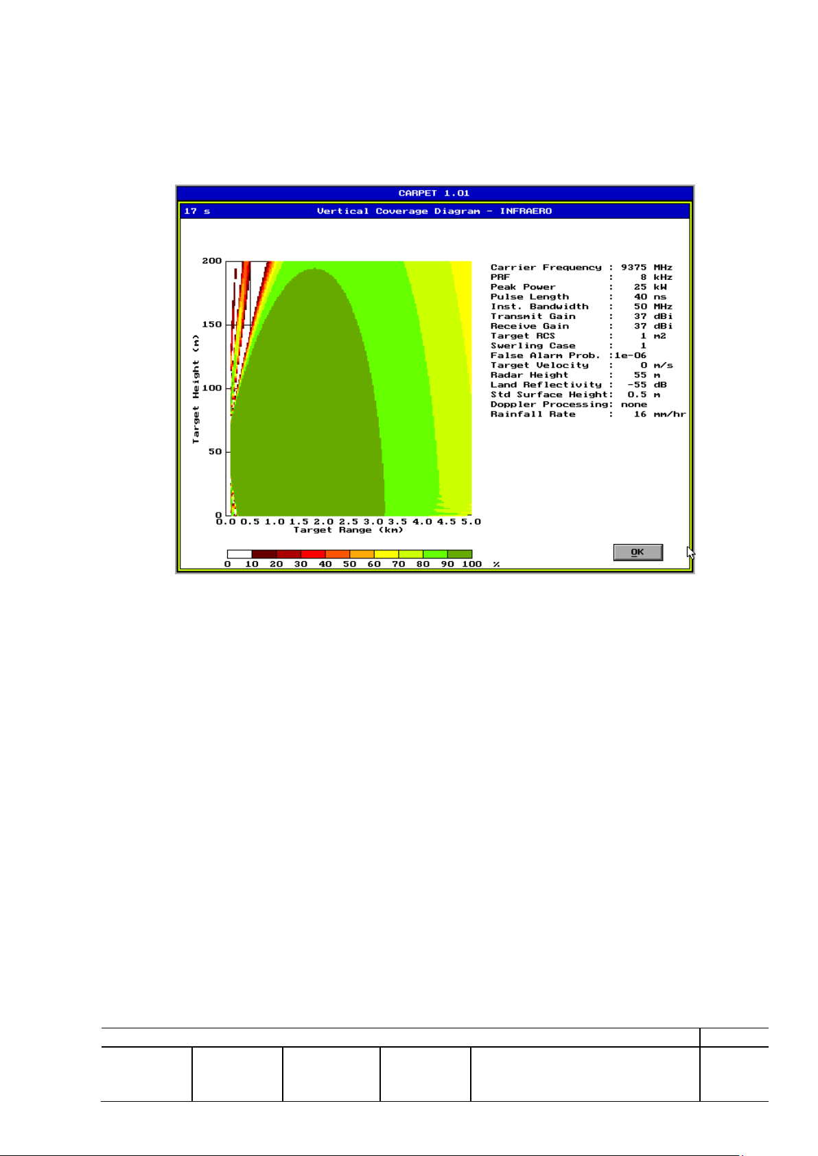
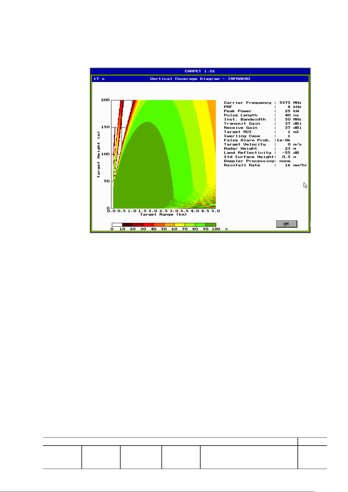
Performance calculations have been performed by analysis using the Computer-Aided Radar
Performance Evaluation Tool (CARPET) from TNO Physics, The Netherlands. Parameters
values are set to handle the very short pulses and taking bounce effects into account by enlarging
the rain cells to give an additional 6 dB rain return compared to a no-bounce situation (giving 9
dB cancellation ratio).
Calculated performance in rain is significantly affected by the rain cancellation achievable by
circular polarisation and especially the amount of single and double bounce energy received via
© TERMA AS, DK-8520 Lystrup, Denmark
Page 23
REV: A
PREP: JET
CHKD: -
APVD: JET
CM: LSN
DOCUMENT NO: 256627 DS
SH: 23
indirect paths. However, practical experience is that rain or snow hardly affects the TERMA
radar sensor systems with circular polarised antennas.
A reflection coefficient of 1 (e.g., from a paved wet surface) will completely eliminate the benefit
from circular polarisation due to single bounce. Practical experience has however shown this not
to be the case due to the fact that airport surfaces consist of a combination of pavements,
vegetation, and larger structures, where (especially wet) vegetation will absorb energy, reducing
the bouncing effect. It is realistic to assume the rain cancellation of a circular polarised antenna to
be reduced from a measured value of 15 dB to the practical value of 8 to 10 dB used in TERMA’s
calculation.
The lobing effect is another parameter that is highly dependent on surface characteristics and also
is influenced by the surface reflectivity.
Surface characteristics have been adapted to set lobing to realistic levels by matching the
roughness to a reflection coefficient of 0.2 at 0.7 grazing angle.
4.1 Target Detection
The combination of a X-band radar-sensor system together with a Circular Polarised antenna
optimises for weather penetration.
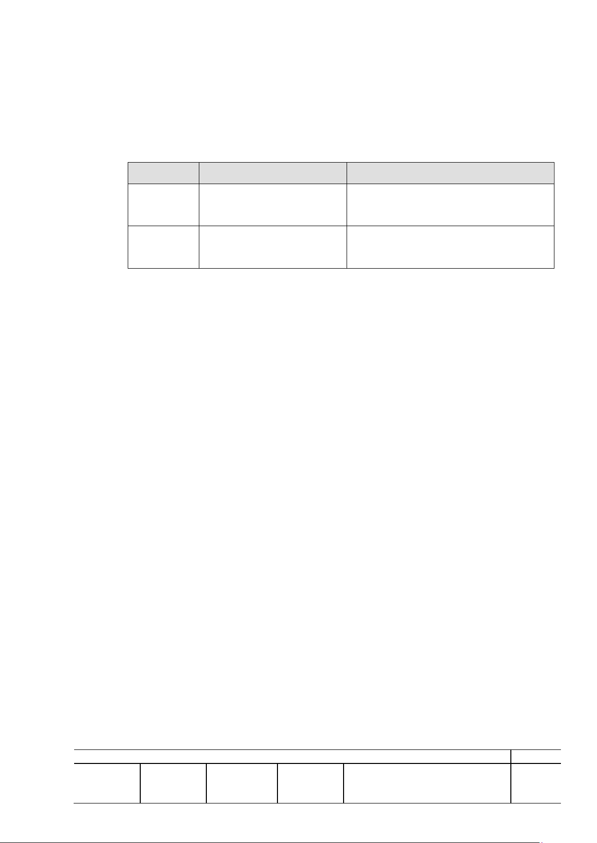
Detection of real targets such as B737s will normally be presented as a round-like spot, and
A340/B747s will be presented with a shape similar to an aircraft.
Figure 4.1-1 shows a Boeing 747 on taxi approximately 500 meters from the radar position as
presented on the service display (VGA resolution).
Figure 4.1-1 TERMA X-Band System (Without Clutter Map)
Aircraft and other mobile targets on an airport occupy 40 dB of the dynamic range at most, after
swept gain on IF. The IF amplifier characteristics are therefore optimised in this region providing
the best possible working conditions.
© TERMA AS, DK-8520 Lystrup, Denmark
Page 24
REV: A
PREP: JET
CHKD: -
APVD: JET
CM: LSN
DOCUMENT NO: 256627 DS
SH: 24
Other structures on an airport may result in very strong returns, and the overall system has
Coverage, Max range [m]
Comment
Scenario #1
180 - 3000 (TWR)
75 - 2500 (Remote)
Performance in 16mm/hr rain
Scenario #2
180 - 4800 (TWR)
75 - 3500 (Remote)
Performance in 4mm/hr rain
therefore been designed to accept input power levels from targets up to 10 dBm without
collapsing or significant pulse stretch as a result.
4.2 Coverage
The coverage is determined by a combination of antenna characteristics, antenna height and local
conditions. The results of the following performance calculations yields:
The short range coverage is calculated using the antenna height and the antenna directivity in
elevation and the VSWR characteristics of the various RF components.
The coverage figures stated herein are based on target locations in clutter free areas i.e. a S/N
ratio larger than app 14-22dB is required to detect the target with a probability of detection larger
than 90%. This means that detection of small targets on grass areas will probably not be possible,
as tests has revealed that a S/N ration in the order 4-8 dB can be expected. This is insufficient to
detect with at least 90% probability. However, this depends a lot on the environment and
topographic in the airport.
Table 4.2-1 Coverage Performance
The coverage stated is valid for 360 degrees.
4.2.1 Performance Calculations
The following constraints are used for the radar performance calculations:
The following generic constraints applies to the coverage figures:
Target size: 1m2
Antenna Height: 55m/23m
Circular Polarised Antenna with –1,5o fixed tilt.
Gain Antenna: >37 dBi
Pd: 90%
Pfa: 10-6
Processing None
Noise Figure 4,7dB
A system loss that includes max 5/15m (TWR/Remote) Wave-guide between equipment room
where the RxTx units is to be located and the antenna is included in the calculations.
Normally the required S/N ration to detect a target with 90% detection probability is app 22dB,
which can be reduced 5-6dB by adding sliding window integration. As detection of the real target
will be correlated in the contrary to the clutter will this improve the detection substantially.
© TERMA AS, DK-8520 Lystrup, Denmark
Page 25
REV: A
PREP: JET
CHKD: -
APVD: JET
CM: LSN
DOCUMENT NO: 256627 DS
SH: 25
Land reflectivity, surface roughness, and rain cancellation set to match experienced performance
form the establishment of SMR systems at several airports in Europe, Asia, and North America in
the following calculations.
a. Performance Scenario #1 (Tower)
Figure 4.2-1 Simulated Performance in precipitation (16mm/hr)
© TERMA AS, DK-8520 Lystrup, Denmark
Page 26
REV: A
PREP: JET
CHKD: -
APVD: JET
CM: LSN
DOCUMENT NO: 256627 DS
SH: 26
b. Performance Scenario #2 (Remote site)
Figure 4.2-2 Simulated Performance in precipitation (16mm/hr)
4.3 Performance - Resolution
The TERMA SCANTER Radar Sensor Systems for SMR applications are optimised to produce
overall clear, crisp radar images virtually independent of the weather. Transmitters are designed
for maximum rise and fall times within those limitations given by the magnetron (especially
avoiding - 1 modes), and receiver IF characteristics are matched to the antenna characteristics
to achieve good overall response.
a. Range
The theoretical range resolution for 40 nS long ideal pulse is 6m; however, this can not be met
due to actual pulse characteristics, dispersion along the signal path, limitations in rise and fall
time, and the digitalisation by sampling. A 40MHz sampling will add additional 3,75m.
Recent installations include novel receiver technology with very fast logarithmic amplifiers,
which furthermore accept a very wide dynamic range without collapsing or significant pulse
stretch. This has improved the picture presentation substantially, in fact giving more crisp
pictures than that achievable from a linear amplifier. Experience is that the resulting resolution
for detection of real targets and small point targets is app 13m plus pixel resolution of the display
at selected range, which is the range resolution that normally, can be verified by testing.
© TERMA AS, DK-8520 Lystrup, Denmark
Page 27

REV: A
PREP: JET
CHKD: -
APVD: JET
CM: LSN
DOCUMENT NO: 256627 DS
SH: 27
b. Azimuth
Azimuth characteristics are almost entirely dependent on the antenna characteristics and the pixel
resolution of the display used for observations, where the -3 dB points on the antenna provide a
theoretical and practical resolution of less than 13m at 2000m for a small target.
However, it is not realistic to assume detection at the -3 dB points in practice of real targets due
to variation in propagation conditions and target fluctuations and size. A practical azimuth
resolution of app 20m at 2000m range should be achievable as it corresponds to approximately 10 dB points on the antenna horizontal radiation pattern.
5 MECHANICAL CAPABILITIES AND CONSTRAINTS.
For details concerning weights, measurements and electrical descriptions of external interfaces
please refer to installation drawings of the RxTx Unit (240100 ZD) and the ACSw (244700 ZD).
6 AVAILABILITY AND MAINTENANCE.
The analysis aims to give a rough indication of the theoretical Mean Time Between Failure
(MTBF) figure for a typical radar system. The estimate is based on MIL-HDBK-217F notice 1.
6.1.1 Environment
Ground Benign (GB), non-mobile, temperature- and humidity-controlled environment readily
accessible to maintenance.
Ambient temperature: 30°C, average.
© TERMA AS, DK-8520 Lystrup, Denmark
Page 28
REV: A
PREP: JET
CHKD: -
APVD: JET
CM: LSN
DOCUMENT NO: 256627 DS
SH: 28
Power AC/DC
Power, DC/DC1
Power, DC/DC2
Magnetron
Pulse Analyser
Modulator
Receiver
Radar Signal Distribution
Internal Interface
Controller
Backplane
Antenna
Encoder
Motor
ACSw Unit
Video Band Compression
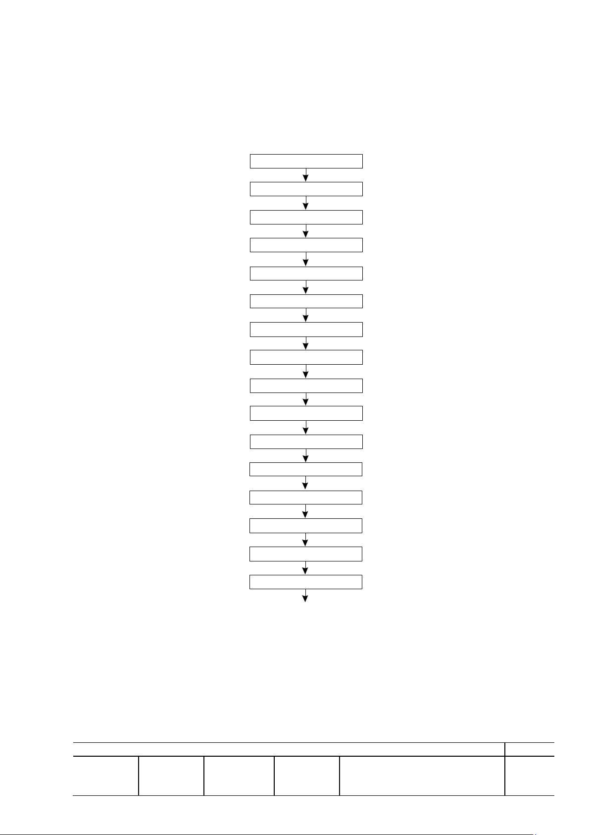
6.1.2 MTBF/MTTR Evaluation
Critical and total MTBFs have been calculated, based on the values in Table 4.3-1 and the
structure in Figure 4.3-1. In the calculation of the total MTBF all modules are considered to be in
series.
Figure 4.3-1 MTBF Path
© TERMA AS, DK-8520 Lystrup, Denmark
Page 29

REV: A
PREP: JET
CHKD: -
APVD: JET
CM: LSN
DOCUMENT NO: 256627 DS
SH: 29
Item Failure rate MTBF Failure rate MTBF MTTR
Hours*10-6 Total, hours Critical Critical, hours Minutes
Antenna *) 20,000 50.000 20,000 50.000 120
ACSw Unit 5,000 200.000 5,000 200.000 40
RxTx Unit
Power, AC/DC 4,440 225.000 4,440 225.000 20
Power, DC/DC 1 3,520 284.000 3,520 284.000 20
Power, DC/DC 2 19,850 50.000 19,850 50.000 20
Magnetron 5,000 200.000 5,000 200.000 40
Pulse analyser group 3,449 290.000 3,449 290.000 30
Modulator, radar, short pulse 1,079 927.000 1,079 927.000 30
Low noise receiver 3,374 296.000 3,374 296.000 40
Radar signal dist. *) 8,000 125.000 4,000 250.000 20
Internal interface (type 2) 8,189 122.000 8,189 122.000 20
Timing, RxTx 12,699 79.000 12,699 79.000 20
Controller, RxTx 2,482 403.000 2,482 403.000 20
Backplane 0,750 1.333.000 0,750 1.333.000 20
Video Band Compression. 9,271 108.000 4,636 216.000 20
Static clutter map 17,166 58.000 4,292 233.000 30
P & NF meter *) 8,000 125.000 20
RxTx, configuration 80,832 12.400 68,832 14.500 20
RxTx, including all features 115,269 8.700 77,759 12.900 20
WGSw Unit 1,016 984.252 1,016 984.000 40
Availability
Single system 106,848 9.400 94,848 10.500
0,99935
Dual redundant system
187,680 5.300 27,393 36.500
0,99949
Dual diversity system, incl. options. 256,554 3.900 27,571 36.300
0,99949
*) Estimated
Magnetrons and bearings are subject to replacement when end of life symptoms start to occur
2% down time for one RxTx is allowed in the critical failure rate to minimize the need for spare parts
4 hours of downtime/year is allowed for preventive maintenance in the availability calculation
2 hours MTTR + access time is allowed in the availability calculations
6.1.3 External Bi-Directional Couplers
To ease external maintenance and measurements of Forward and Reverse Power is a coupler
included with the following microwave characteristics:
Coupling Forward Power: 30 dB
Coupling Reverse Power: 20 dB
Directivity >15 dB
Connections for Test equipment: N-female
Table 4.3-1 MTBF Figures
The coupler will be provided with a calibration test sheet for exact coupling figures.
© TERMA AS, DK-8520 Lystrup, Denmark
Page 30

REV: A
PREP: JET
CHKD: -
APVD: JET
CM: LSN
DOCUMENT NO: 256627 DS
SH: 30
7 INSTALLATION MATERIAL
Internally the transmitter and antenna is used WR90 wave-guide and between the units will be
used Andrew size 85 elliptical waveguide or similar from RFS. The waveguide switch used is a
Sivers model WS 8089X/00.
System is delivered preinstalled on radar sensor subsystem level in order to ensure optimum
workmanship, minimise on site installation work.
All necessary parts and hardware, including receptacles, connectors, coaxial and cabling (wiring),
waveguide adapters required to assemble the system is included in the installation activities.
However, the media between the radar equipment and the remote control and monitoring position
is not included.
The installation and system assembly on site will be made in according with the standard
TERMA installation guidance, 244112 PD.
The overall VSWR for the complete installation including the antenna is normally seen less than
1:1,4. This value will not have any significant impact on the performance.
The VSWR requirement for the complete antenna including rotating joint alone is 1:1,2
© TERMA AS, DK-8520 Lystrup, Denmark
 Loading...