

Page 1

Simplifying System In tegrationTM
73S1209F
Evaluation Board User Guide
August 19, 2009
Rev. 1.3
UG_1209F_034
Page 2

73S 1209F Evaluation Board User Guide UG_1209F_034
© 20 09 Teridi an Semiconductor C or porati on. All rights r eserved .
Teridian Semiconductor Corporation is a registered trademark of Teridian Semiconductor Corporation.
Simplifying System Integration is a trademark of Teridi an Semiconductor C or poration .
Microsoft, Windows and Vista are register ed trademar ks of Micr osoft Corporation.
Signum is a trademark of Si gnum Systems Corporation.
Keil i s a trademark of ARM® Ltd.
All other trademar ks are the pr operty of their respective o wn ers.
Terid i an Semiconductor Corporation m akes no warranty for the use of its p r oduct s, other than expressly
contained in the Company’s warr anty d etailed in the Terid ian S emiconductor Corporation st andar d Terms
and C onditions. The company assu mes no responsib i lity for any errors whi ch may appear in this
document, reserves th e r i ght to change device s or sp ecifications detailed herein at any time withou t
notice and does n ot make any commitm ent to upd ate the information contained herein. Accordingl y, the
reader is cautioned to verify that t his document is current by comparing it to the latest version on
http://www.teridian.com or by checking with your sales repres entative.
Terid i an Semiconductor Corp., 64 40 Oak Canyon, Suite 100, Ir vine, CA 92618
TEL (714) 508-8800, FAX (714) 508-8877, http://www.teridian.com
2 Rev. 1.3
Page 3

UG_1209F_034 73S1209F Evaluation Board User Guide
Table of Contents
1
Introduction ................................................................................................................................... 4
1.1 Evaluat i on Ki t Contents ......................................................................................................... 5
1.2 Evaluat i on Board Feat ures .................................................................................................... 5
1.3 Recommended Equipment and Test Tools ............................................................................ 5
2 Evaluation Board Setup................................................................................................................. 6
2.1 Connecting the Evaluation Board with an Emulation Tool ...................................................... 7
2.2 Loading U ser Code i nto the Evaluati on Board ....................................................................... 8
3 Using the PCCID Application ...................................................................................................... 10
3.1 Host Demonstration S oftware Instal lation ............................................................................ 10
4 Evaluation Board Hardware Description .................................................................................... 11
4.1 Jumpers, Swit ches and Modules ......................................................................................... 11
4.2 Test Points ......................................................................................................................... 16
4.3 Schematic........................................................................................................................... 17
4.4 PCB Layouts....................................................................................................................... 18
4.5 Bill of Materials ................................................................................................................... 24
4.6 Schem atic Information ........................................................................................................ 27
4.6.1 Reset Circuit.............................................................................................................. 27
4.6.2 Oscillators ................................................................................................................. 27
4.6.3 LCD .......................................................................................................................... 28
4.6.4 Smart Card Interface ................................................................................................. 29
5 Ordering Information ................................................................................................................... 30
6 Related Documentation ............................................................................................................... 30
7 Contact Information ..................................................................................................................... 30
Revision H istory .................................................................................................................................. 31
Figures
Figure 1: 73S1209F Evaluation Board ..................................................................................................... 4
Figure 2: 73S1209F Evaluation Board Basic Conn ections
Figure 3: 73S1209F Evaluation Board Basic Conn ections with ADM-51 ICE
Figure 4: Emulator Window Showing RESET and ERASE Buttons
Figure 5: Emulator Wind ow Showing Erased Flash Memory and File Load Menu
Figure 6: 73S1209F Evaluation Board Jumper, S witch and Module Locations
Figure 7: 73S1209F Evaluation Board Electr i cal Schemat ic
Figure 8: 73S1209F Evaluation Board Top Vi ew (Silkscreen)
Figure 9: 73S1209F Evaluation Board Bot tom View (Silkscreen)
Figure 10: 73S1209F Evaluation Board Top Si gnal Layer
Figure 11: 73S1209F Evaluation Board Middle Layer 1 – Ground Plane
Figure 12: 73S1209F Evaluation Board Mid dle L ayer 2 – Supply Plane
Figur e 13: 73 S1209F Eva l ua tion Board Bottom Signal Layer
Figure 14: Extern al Components for RESET
Figure 15: Oscillator Circu it
Figure 16: LCD Connecti ons
Figure 17: Smart C ar d Con nect i ons
Tables
Table 1: Flash Programming Interface Signals ......................................................................................... 8
Table 2: Evaluation Board Jumper, Switch and Module Description
Table 3: Evaluation Board Test Point Description
Table 4: 73S1209F Evaluat ion B oar d Bil l of Mater ials
........................................................................ 6
............................................ 7
........................................................... 9
..................................... 9
........................................ 15
................................................................... 17
................................................................. 18
............................................................ 19
...................................................................... 20
................................................. 21
................................................. 22
................................................................. 23
.......................................................................................... 27
.................................................................................................................... 27
.................................................................................................................. 28
....................................................................................................... 29
....................................................... 11
................................................................................... 16
............................................................................ 24
Rev. 1.3 3
Page 4
73S 1209F Evaluation Board User Guide UG_1209F_034
1 Introduction
The Teridian Semiconductor Corporation (TSC) 73S1209F Evaluat ion B oar d is use d to demonstrate the
capabilities of the 73S1209F Smart Card Cont r ol ler device. It has been desi gned to operate either as a
standalone or as a develop ment platform.
The 73S1209F Evaluation Board can be programmed to run any of the Teridi an turnke y appli cations or a
user-developed cust om application. Teridian provides its USB CCID application preloaded on the board
and an EMV testing application on t he CD.
Appli cations can be downloaded through the In-Circuit-Em ulator ( ICE) or through the TSC Flash
Programmer Mod el TFP2. As a developm ent tool, th e evaluation board can operate in conjunction with
an ICE to develop and debug 73S1209F based embedded applications.
The 73S1209F Evaluation Board uses the same PWB as the 73S1215F. The 73S1215F has
some features that the 73S1209F does not contain. Th ese include the 32 kH z oscillator, USB
interface, LED2 and LE D 3. These feat ures are depopulated on th e 73S1209F.
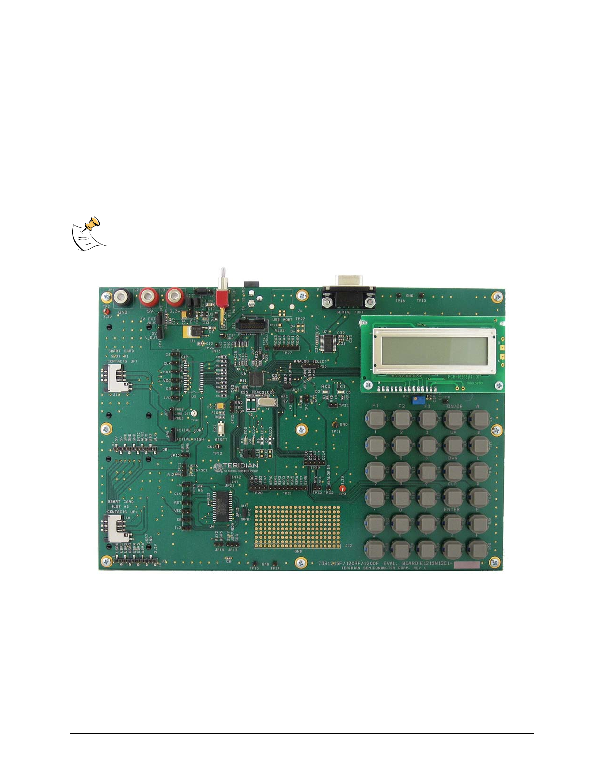
Figure 1: 73S1209F Evaluation Board
4 Rev. 1.3
Page 5

UG_1209F_034 73S 1209F Evaluation Board User Guide
1.1 Evaluation Kit Contents
The 73S1209F Evaluation Kit contains the following:
• 73S1209F Evaluation Boar d: 4-layer, r ectan gul ar PWB as shown in Figure 1 (identification n um ber
E12 15N12C1 Rev C), co ntainin g the 73S1209F with the preloaded turnkey program PCCID.
• 12 VDC/1,000 mA universal wall transformer with 2.1 mm plug ID (CUI Inc. – EPAS-101W-12).
• Serial cable: DB9, male/female, 2 meter length (Digi-Key AE1379-ND).
• CD containing d ocumentation (dat a sheet, and use r guides), Software API l ibraries, evaluation c ode,
and utilities.
1.2 Evaluation Board Fe atures
The 73S1209F Evaluation Board (see Figure 1) includes the following:
• RS-232 interface
• Dual smart card interface
• ICE/Programmer interface
• 2 line x 16 character LCD module
• 6 x 5 Keypad
• 2 LEDs
1.3 Recommended Equipment and Test Tools
The following equipment and tools ( not provided) are recommended for use with the 73S12 09F
Evaluation Kit:
• For functional evaluation: PC with Microsoft® Windows® XP or Vista®.
• For software devel opm ent (MPU code)
Signum™ ICE (In C ircuit Emulator): ADM-51 . R efer to
http://signum.temp.veriohosting.com/Signum.htm.
Keil™ 8051 C Compiler Kit: CA 51. Refer to http://www.keil.com/c51/ca51kit.htm and
http://www.keil.com/product/sales.htm
Rev. 1.3 5
 Loading...