

Page 1

Simplifying System In tegrationTM
73S1215F
Evaluation Board User Guide
August 17, 2009
Rev. 1.8
UG_1215F_039
Page 2

73S 1215F Evaluation Board User Guide UG_1215F_039
© 20 09 Teridi an Semiconductor C or porati on. All rights r eserved .
Teridian Semiconductor Corporation is a registered trademark of Teridian Semiconductor Corpor ation.
Simplifying System Integration is a trademark of Teridi an Semiconductor C or poration .
Microsoft, Windows and Vista are register ed trademar ks of Micr osoft Corporation.
Linux is a registered trademark of L i nus Tor valds.
Signum is a trademark of Si gnum Systems Corporation.
Keil i s a trademark of ARM
®
Ltd.
Slackware is a r egistered trademark of Patrick V olkerding and Sl ackware Linux, Inc.
Fedora i s a registered t r ademar k of RedHat, I nc.
All other trademar ks are the pr operty of their respective o wn ers.
Terid i an Semiconductor Corporation m akes no warranty for the use of its p r oduct s, other than expressly
contained in the Comp any’s warranty d etailed in the Terid ian S emiconductor Corporation st andar d Terms
and C onditions. The company assu mes no responsib i lity for any errors whi ch may appear in this
document, reserves th e r i ght to change device s or sp ecifications detailed herein at any time withou t
notice and does n ot make any commitm ent to upd ate the information contained herein. Accordingl y, the
reader is cautioned to verify that t his document is current by comparing it to the latest version on
http://www.teridian.com or by checking with your sales repres entative.
Terid i an Semiconductor Corp., 64 40 Oak Canyon, Suite 100, Ir vine, CA 92618
TEL (714) 508-8800, FAX (714) 508-8877, http://www.teridian.com
2 Rev. 1.8
Page 3

UG_1215F_039 73S1215F Evaluation Board User Guide
Table of Contents
1 Introduction ................................................................................................................................... 5
1.1 Evaluation Kit C ontents ......................................................................................................... 6
1.2 Evaluation Board Featu r es .................................................................................................... 6
1.3 Recommended Equ ipment and Test Tools ............................................................................ 6
2 Evaluation Board Basic Setup ...................................................................................................... 7
2.1 Connecti ng the Evaluati on Board with an Emulation Tool ...................................................... 8
2.2 Load i ng U ser Code into the Evaluat ion B oar d ....................................................................... 9
3 Using the USB CCID Application ................................................................................................ 11
3.1 Driver and H ost Demonstrati on Soft ware In stallation ........................................................... 11
3.1.1 Installation on Wind ows XP ....................................................................................... 11
3.1.2 Driver and Software Installation on a Lin ux Syst em .................................................... 12
3.2 Fre que nt ly Asked Questions ............................................................................................... 12
4 Evaluation Board Hardware Description .................................................................................... 14
4.1 Jumpers, Switch es and Modules ......................................................................................... 14
4.2 Test Poi nts ......................................................................................................................... 20
4.3 Schematic........................................................................................................................... 21
4.4 PCB Layouts....................................................................................................................... 22
4.5 Bill of Materials ................................................................................................................... 28
4.6 Schematic In formati on ........................................................................................................ 31
4.6.1 Reset Circuit.............................................................................................................. 31
4.6.2 Oscillators ................................................................................................................. 31
4.6.3 LCD .......................................................................................................................... 32
4.6.4 USB In terface ............................................................................................................ 32
4.6.5 Smart Card Interface ................................................................................................. 33
5 Ordering Information ................................................................................................................... 34
6 Related Documentation ............................................................................................................... 34
7 Contact Information ..................................................................................................................... 34
Revision H istory .................................................................................................................................. 35
Rev. 1.8 3
Page 4

73S 1215F Evaluation Board User Guide UG_1215F_039
Figures
Figure 1: 73S1215F Evaluation Board ..................................................................................................... 5
Figure 2: 73S1215F Evaluation Board Basic Conn ections
Figure 3: 73S1215F Evaluation Board Basic Conn ections with ADM-5 1 ICE
Figure 4: Emulator Window Showing RESET and ERASE Buttons
Figure 5: Emulator Wind ow Showing Erased Flash Memory and File Load Menu
Figure 6: Board Setup for t he USB-CCID Application
Figure 7: 73S1215F Evaluation Board Jumper, S witch and Module Locations
Figure 8: 73S1215F Evaluation Board Electrica l Schematic
Figure 9: 73S1215F Evaluation Board Top Vi ew (Silkscreen)
Figure 10: 73S1215F Evaluation Board Bot tom Vi ew (Silkscreen)
Figure 11: 73S1215F Evaluation Board Top Si gnal Layer
Figure 12: 73S1215F Evaluation Board Mid dle L ayer 1 – Gr ound Pl ane
Figure 13: 73S1215F Evaluation Board Mid dle L ayer 2 – Supply Plane
Figure 14: 73S1215F Evaluation Board Bot tom Si gnal L ayer
Figure 15: Extern al Components for RESET
Figure 16: Oscillator Circu it
Figure 17: LCD Connecti ons
Figure 18: USB C onnect ions
Figure 19: Smart C ar d Con nect i ons
Tables
........................................................................ 7
............................................ 8
......................................................... 10
................................... 10
............................................................................. 12
........................................ 19
................................................................... 21
................................................................. 22
.......................................................... 23
...................................................................... 24
................................................. 25
................................................. 26
................................................................. 27
.......................................................................................... 31
.................................................................................................................... 31
.................................................................................................................. 32
.................................................................................................................. 32
....................................................................................................... 33
Table 1: Flash Programming Interface Signals ......................................................................................... 9
Table 2: Evaluation Board Jumper, Switch and Module Description
Table 3: Evaluation Board Test Point Description
Table 4: 73S1215F Evaluat ion B oar d Bil l of Mater ials
....................................................... 14
................................................................................... 20
............................................................................ 28
4 Rev. 1.8
Page 5
UG_1215F_039 73S 1215F Evaluation Board User Guide
1 Introduction
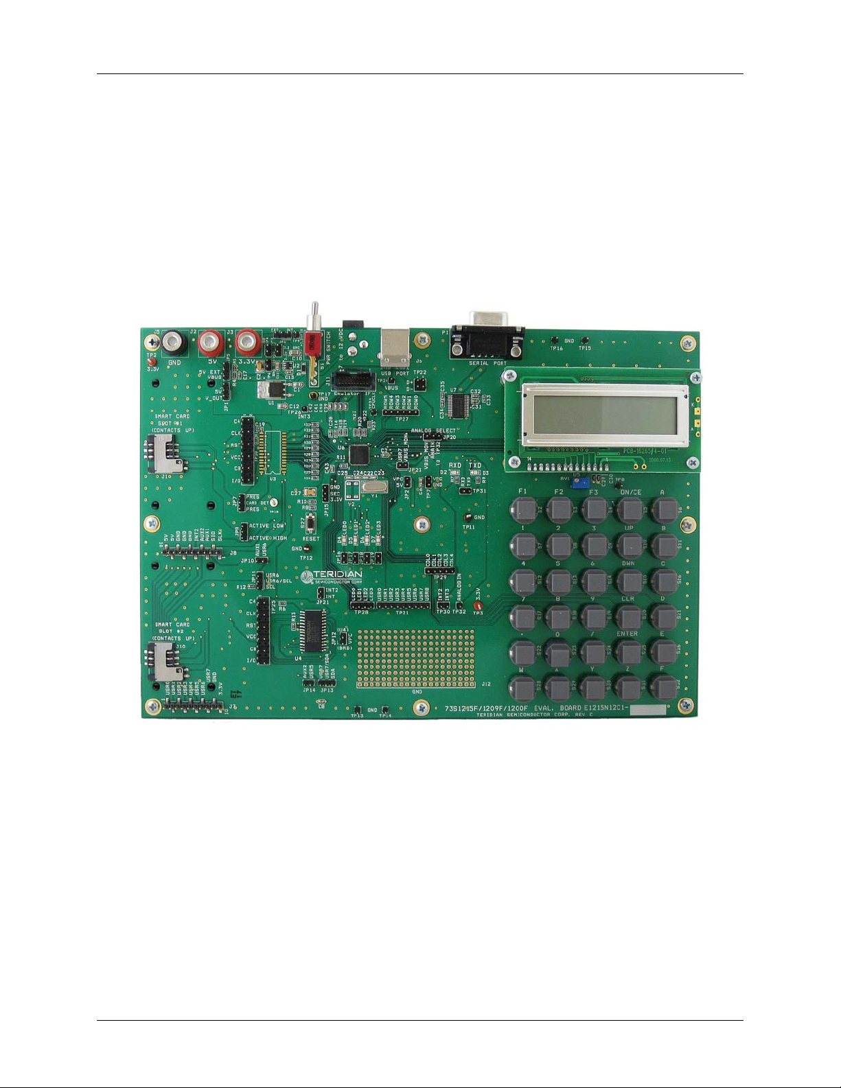
The Teridian Semiconductor Corporation (TSC) 73S1215F Evaluation Board i s used to demonstrate the
capabilities of the 73S1215F Smar t Card Contr oller device. It has been designed to operat e either as a
standalone or a devel o pme nt platform.
The 73S1215F Evaluation Board can be progr am med to run any of the Teridian turnkey applications or a
user-developed cust om application. Teridian provides its U SB CCI D application preloaded on the board
and an EMV testing application on t he CD.
Applications can be downloaded through the In-Circuit-Emulator ( ICE) or through the TSC Flash
Programmer Mod el TFP2. As a developm ent tool, th e evaluation board has been designed to operate in
conjunction with an ICE to develop and debug 73S1215F based em bedded applications.
Figure 1: 73S1215F Evaluation Board
Rev. 1.8 5
Page 6

73S 1215F Evaluation Board User Guide UG_1215F_039
1.1 Evaluation Kit Contents
The 73S1215F Evaluation Kit contains the following:
• 73S1215F Evaluation Board: 4-layer, rectangular PWB as shown i n Figure 1 (iden ti fication number
E12 15N12C1 Rev C), conta i ni ng the 73 S1215F with the preloaded turnkey program USB CCID.
• 12 VDC/1,000 mA universal wall transformer with 2.1 mm plug ID (CUI Inc. – EPAS-101W-12).
• USB cable, A-B, male/male, 2 meters (Digi-Key AE9932-ND)
• CD containing d ocumentation (dat a sheet, and user guides), software API libr ar i es, evaluation code,
and utilities.
1.2 Evaluation Board Fe atures
The 73S1215F Evaluat i on Board (see Figure 1) includes the following:
• USB 2.0 full speed interface
• RS-232 interface
• Dual smart card interface
• ICE /Programmer interface
• 2 line x 16 character LCD module
• 6 x 5 keypad
• Real Time Clock (RTC) capability
• 4 LEDs
1.3 Recommended Equipment and Test Tools
The following equipment and tools ( not provided) are recomm ended for use with the 73S1215F
Evaluation Kit:
• For functional evaluation: PC with Microsoft® Windows® XP or Vista®, or a workstation runnin g Li n ux®
equipped with an USB port.
• For software devel opm ent (MPU code)
Signum™ ICE (In C ircuit Emulator): ADM-51 . R efer to
http://signum.temp.veriohosting.com/Signum.htm.
Keil™ 8051 C Compil er Kit: CA51. Refer to http://www.keil.com/c51/ca51kit.htm and
http://www.keil.com/product/sales.htm.
6 Rev. 1.8
 Loading...