

Terex TS14G, TS14F Maintenance Manual
TS14G
Overhung Scraper
Maintenance Manual
SM 1882 Rev 1 3-01
TECHNICAL PUBLICATIONS DEPARTMENT
TEREX EQUIPMENT LIMITED,
MOTHERWELL, SCOTLAND, ML1 5RY
REF. NO. 790

THIS PAGE IS INTENTIONALLY LEFT BLANK

Service
The information contained within this
Alert must not be made available to
third parties not authorised to receive it.
Information
Alert
DATE: April 1994 B168
MODEL: General
SUBJECT: VITON 'O' RINGS AND SEALS (FLUORO-ELASTOMERS) - SAFETY HAZARDS
PURPOSE:
To advise potentially hazardous condition.
DETAIL:
It has been brought to our attention that 'Viton' material used in manufacture of oil seals and 'O' rings, produces a
highly corrosive acid (Hydrofluoric) when subjected to temperatures above 315° C.
The resulting contamination can have extreme consequences on human tissue since it is almost impossible to
remove after contact.
We therefore recommend the following procedure when it is necessary to inspect any equipment that has been
subjected to a high temperature i.e. fire.
a. Visually inspect for any gaskets or seals which have suffered from heat; they will appear black and sticky.
b. If this is affirmed - Do Not Touch
c. Make enquiries to ascertain the material composition. Any Fluoro-elastomer (Viton, Fluorel or Tecmoflon)
should be considered dangerous but natural rubber and nitrile are non-hazardous.
d. If Fluoro-elastomer seals have been used, then the affected area MUST be decontaminated before
undertaking further work.
e. Disposable Heavy Duty Gloves (Neoprene) MUST be worn and the affected area decontaminated by washing
thoroughly with Limewater (Calcium Hydroxide solution).
f. Any cloths, residue and gloves used MUST be safely discarded after use.
Note: Burning of the discarded items is NOT RECOMMENDED, except in an approved incineration process
where the gaseous products are treated by alkaline scrubbing.
TEREX SERVICE DEPARTMENT
TEREX Equipment Limited, Motherwell, Scotland ML1 5RY Tel. (0698) 732121 Tlx. 77141 Fax. (0698) 734046
TEREX Division, Tulsa, Oklahoma, 74107 USA Tel. (918) 446-5581 Fax. (918) 446-9752

THIS PAGE IS INTENTIONALLY LEFT BLANK
IMPORTANT SAFETY NOTICE
Proper service and repair is important to the safe, reliable operation of all motor vehicles. The service
procedures recommended and described in this publication, are effective methods for performing service
operations. Some of these service operations require the use of tools specially designed for the purpose.
The special tools should be used when, and as recommended.
It is important to note that this publication contains various WARNINGS and NOTES which should be
carefully read in order to minimize the risk of personal injury to personnel, or the possibility that improper
service methods will be followed which may damage the vehicle or render it unsafe. It is also important to
understand these WARNINGS and NOTES are not exhaustive. It is not possible to know, evaluate and
advise the service trade of ALL conceivable ways in which service might be carried out, or, of the
possible hazardous consequences of each way. Consequently, no such broad evaluation has been
undertaken. Accordingly, anyone who uses a service procedure, or tool, which is not recommended, must
first satisfy themselves thoroughly that neither their safety, nor vehicle safety, will be jeopardized by the
service method he/she selects.
Two types of heading are used in this manual to attract your attention.
1. WARNING - This symbol is used when an operating procedure, practice, etc., which, if not correctly
followed could result in personal injury or loss of life. Look for this symbol to point out important safety
precautions. It means - ATTENTION! BECOME ALERT! YOUR SAFETY IS INVOLVED!
2. Note - This is used when an operating procedure, practice, etc., which, if not strictly observed, could result in
damage to or destruction of equipment.
WARNING
Never use parts which are altered, modified, or weakened in operation. This can seriously
jeopardize the integrity of the machine and could result in property damage or serious personal
injury.
SM 222 Rev 1 9-93

THIS PAGE IS INTENTIONALLY LEFT BLANK

TABLE OF CONTENTS
Section No. Description SM No.
000 GENERAL INFORMATION
0000 TS14G Technical Data 1884
100 CHASSIS
0010 Chassis, Hood and Fenders - Tractor 1885
0130 Steering Trunnion - Tractor 1695
110 ENGINE
0030 Engine and Mounting 1691 Rev 2
0050 Air Cleaner 1692
0130 Power Takeoff - Tractor 1693
0130 Flywheel Cover Group - Scraper 1694
120 TRANSMISSION
0010 Transmission Mounting 1783
0070 Transmission Electronic Controls 1735
13 0 DRIVELINE
0010 Drivelines - Front and Rear 1796
14 0 FRONT AXLE GROUP
0030 Planetary Gearing (Refer to Section 160-0040) 0040 Wheel, Rim and Tyre (Refer to Section 160-0050) 0060 Differential 1778
16 0 REAR AXLE GROUP
0020 Differential 1780
0040 Planetary Gearing 1779
0050 Wheel, Rim and Tyre 1721
0080 NoSpin Element 1781
165 BRAKE PARTS
0031 Brake Parts - Scraper 1777
0060 Slack Adjuster 1751
19 0 ELECTRICAL SYSTEM
0000 Circuit Diagrams 1789
0270 Switches and Sensors 1792
200 FUEL SYSTEM
0040 Fuel Tanks, Lines and Mounting 1886
0051 Electronic Foot Pedal 1719
21 0 COOLING SYSTEM
0040 Radiator and Mounting 1723 Rev 1
0060 Transmission Oil Cooler 1798
22 0 STEERING SYSTEM - TRACTOR
0000 Steering System Schematic 1760
0010 Steering Lines and Fittings 1768 Rev 1
0090 Steering Valve 1765
0120 Steering Cylinder 1897
0130 Double Relief Valve 1747
0160 Flow Reversing Valve 1764
0190 Steering Linkage 1766
SM 1883 Rev 1 3-01
1

TABLE OF CONTENTS
Section No. Description SM No.
23 5 BOWL HYDRAULIC SYSTEM
0000 Hydraulic System Schematic 1893
0010 Hydraulic Lines and Fittings 1894
0020 Bowl Cylinder 1769
0030 Ejector Cylinder 1895
0035 Apron Cylinder 1896
0040 Hydraulic Tank - Tractor 1722
0050 Triple Pump 1739
0060 Bowl Control Valve 1887
0070 Accumulator 1791
0120 Relief Valve 1776
0160 Servo Control Valve 1775
25 0 BRAKING SYSTEM
0000 Air Braking System Schematic 1784 Rev 1
0070 Treadle Valve 1755
0170 Air Tanks and Mounting 1788
0180 Quick Release Valve 1793
0190 Park/Emergency Brake Control Valve 1795
0200 Air Drier 1753
0260 Brake Chamber 1782
0280 Relay Emergency Valve 1800
0280 Relay Valve 1794
0290 Pressure Protection Valve 1752
25 5 AIR SYSTEM
0020 Air Horn 1797
260 OPERATOR'S COMPARTMENT
0010 Cab and Mounting 1728 Rev 1
0090 Driver Seat and Mounting (Air Suspension) 1742 Rev 1
0130 Air Conditioning 1787
28 0 BOWL - SCRAPER
0010 Bowl and Tail 1799 Rev 1
0020 Pull Yoke 1888
0030 Apron and Ejector 1890
0040 Ejector Lever 1892
0040 Bowl Linkage 1891
0050 Cutting Edges and Side Blades 1726
300 MISCELLANEOUS
0020 Lubrication System 1889
0070 Service Tools 1802 Rev 1
0080 Standard Bolt and Nut Torque Specs 1238
0090 Unit Storage 1239
2
* * * *
SM 1883 Rev 1 3-01
GENERAL INFORMA TION - TS14G T echnical Data
Section 000-0000
SM - 2376
3 440 (11-3.5) Max. Width
3 060
(10-0.5)
2 260
(7-5)
1 460
(4-9.5)
3 250
(10-8)
2 770 (9-1) 2 590 (8-6)
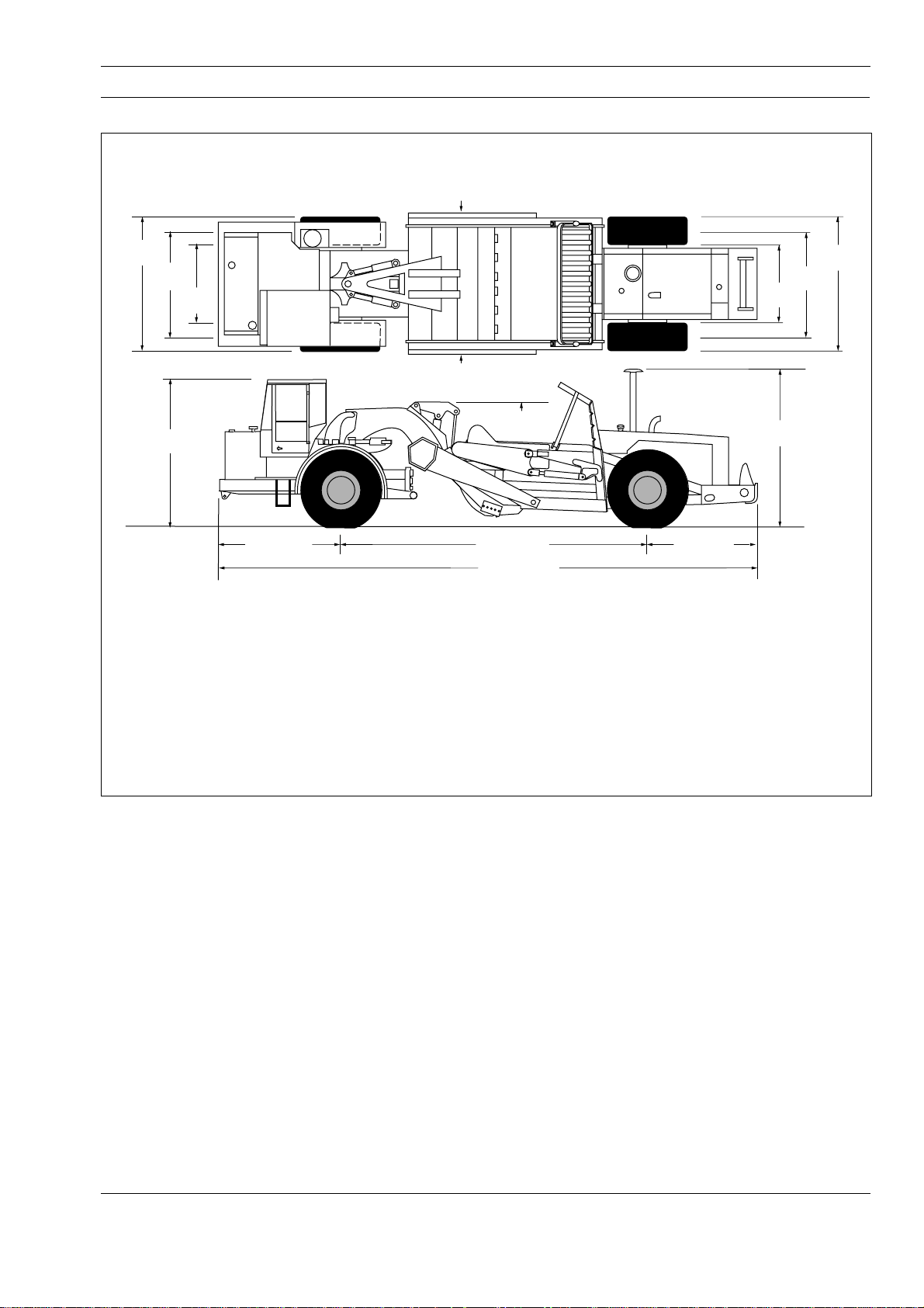
All vertical dimensions with bowl at 300 mm (12 in) carry position. Unit empty.
Apron opening .................................. 2 100 mm (6 ft 11 in)
Width of Bowl and Cutting Edge ......... 2 910 mm (9 ft 7 in)
Width of cut .......................................3 000 mm (9 ft 10 in)
Depth of cut - maximum......................... 305 mm (1 ft 0 in)
Depth of spread - maximum .................. 685 mm (2 ft 3 in)
Clearance under drive axle.................. 585 mm (1 ft 11 in)
Clearance under bowl - maximum .......585 mm (1 ft 11 in)
2 260
(7-5)
1 460
(4-9.5)
3 150 (10-4)
to ground
7 040 (23-1)
12 400 (40-8)
Dimensions in mm (ft-in)
3 810
(12-6)
Dimensions in mm (ft-in)
Overall length with optional Twin Hitch
Bail Raised...................................... 13 900 mm (45 ft 7 in)
Bail Lowered ................................... 14 340 mm (47 ft 8 in)
Note: All vertical measurements are with bowl at 300 mm
(12 in) carry position. Unit empty.
3 060
(10-0.5)
Fig. 1 - Machine Dimensions
ENGINE
Tractor
Engine Series .......................Detroit Diesel Series 40E
Type ............................ 4 Cycle Diesel, Turbocharged,
Electronic Management
Gross power at 2 200 rev/min............ 136 kW (185 hp)
Net power at 2 200 rev/min................ 123 kW (167 hp)
Note: Gross power rated to SAE J1995 June 90.
Engine emission meets USA EPA/CARB MOH 40
CFR 89 and EU NRMM (non-road mobile
machinery) directive.
Maximum Torque
at 1 600 rev/min............................. 720 Nm (531 lbf ft)
Number of cylinders/configuration ...................6, Inline
Bore x Stroke................ 109 x 136 mm (4.30 x 5.35 in)
Total Displacement...........................7.6 litres (466 in³)
SM 1884 1-00
Air cleaner .............................................Dry, Aspirated
Starting .............................................................Electric
Maximum Speed (No load) .....................2 450 rev/min
Maximum Speed (Full load).................... 2 200 rev/min
Idle Speed .................................................700 rev/min
Safe Operating Angle ..........................30°/57% Grade
Scraper
Engine Series .......................Detroit Diesel Series 40E
Type ............................ 4 Cycle Diesel, Turbocharged,
Electronic Management
Gross power at 2 200 rev/min............ 123 kW (167 hp)
Net power at 2 200 rev/min................ 113 kW (153 hp)
Note: Gross power rated to SAE J1995 June 90.
Engine emission meets USA EPA/CARB MOH 40
CFR 89 and EU NRMM (non-road mobile
machinery) directive.
1

General Information - TS14G Technical Data
Section 000-0000
Maximum Torque
at 1 600 rev/min............................. 644 Nm (475 lbf ft)
Number of cylinders/configuration ...................6, Inline
Bore x Stroke................ 109 x 136 mm (4.30 x 5.35 in)
Total Displacement...........................7.6 litres (466 in³)
Air cleaner .............................................Dry, Aspirated
Starting .............................................................Electric
Maximum Speed (No load) .....................2 450 rev/min
Maximum Speed (Full load).................... 2 200 rev/min
Idle Speed ................................................. 700 rev/min
Safe Operating Angle ..........................30°/57% Grade
TRANSMISSION
Make/Model........................... Funk DF158 Powershift,
counter-shaft type transmission with integral torque
converter. Seven speeds forward and one reverse.
Automatic lockup in the top six forward gears.
Manual, electric shifting and downshift inhibitor. Rear
transmission is equipped with an alarm to warn the
operator in the event of transmission malfunction.
SPEEDS WITH STANDARD DIFFERENTIAL
Forward
Gear 1234567
Ratio 5.72 4.05 2.90 2.03 1.45 1.03 0.74
km/h 5.9 8.3 11.5 16.5 23.1 32.5 45.4
mile/h 3.6 5.1 7.2 10.2 14.3 20.2 28.2
Reverse
Ratio 4.05
km/h 8.3
mile/h 5.1
Stall Speed .............................................1 885 rev/min
Torque Converter Ratio (front and rear) .......... 2.408:1
AXLES
Heavy duty axles with fully-floating axle shafts, single
reduction bevel gear differential and planetary
reduction in each wheel. A NoSpin differential is
standard in the rear axle for improved traction in
difficult conditions. A pedal controlled power-locking
differential is optional in the front axle, operational in
first gear only.
BRAKES
Full air operated drum brakes with automatic
application on loss of air pressure. Secondary system
can also be manually applied. Spring-applied parking
brake actuators. Air drier standard.
Braking Lining:
Diameter.............................................. 508 mm (20 in)
Shoe Width............................................ 152 mm (6 in)
Lining Thickness................................. 19 mm (0.75 in)
Lining Area - Each Axle ................. 3 355 cm² (520 in²)
Air Compressor Capacity..... 374 litre/min (13.2 ft³/min)
WHEELS AND TYRES
Wheel Rim Width................................................. 25 in
Tyres:
Standard....................................... 29.5 R25** Radial
Optional .......................................29.5-25 (28PR) E3
Note: Consult tyre manufacturers for optimum tyre
selection and correct t-km/h (ton-mileh) capacity for
application.
STEERING SYSTEM
Full hydraulic type provided by two interchangeable
single stage, double acting steering cylinders. Steering
cylinders are mounted below the gooseneck to aid
stability.
System Pressure ....................... 135 bar (1 950 lbf/in²)
at 1 500 rev/min
Steering Cylinder:
Bore and Stroke .......... 140 x 445 mm (5.5 x 17.5 in)
Pump:
Type ................................................................. Gear
Drive......................... In tandem with hydraulic pump
Capacity at 2 200 rev/min...................... 147 litre/min
(38.7 US gal/min)
Steering Angle to either side...................................90°
Vehicle clearance circle (SAE) .................. 10 m (33 ft)
HYDRAULICS AND CONTROLS
Hydraulic system is filtered and has one reservoir
supplying a triple section gear pump for steering and
scraper hydraulics.
Ratios:
Differential ...................................................... 4.11:1
Planetary ........................................................ 5.33:1
Total Reduction ............................................ 21.91:1
2
Scraper Functions:
Capacity at 2 200 rev/min...................... 270 litre/min
(71.2 US gal/min)
System Pressure
at 1 500 rev/min................ 127.5 bar (1 850 lbf/in²)
SM 1884 1-00
 Loading...