

Terex TR100 Maintenance Manual

TR100
Mining Truck
Maintenance Manual
SM 1616 Rev 1 11-00
TECHNICAL PUBLICATIONS DEPARTMENT
TEREX EQUIPMENT LIMITED,
MOTHERWELL, SCOTLAND, ML1 5RY
REF. NO. SM755/783

THIS PAGE IS INTENTIONALLY LEFT BLANK
IMPORTANT SAFETY NOTICE
Proper service and repair is important to the safe, reliable operation of all motor vehicles. The service
procedures recommended and described in this publication, are effective methods for performing service
operations. Some of these service operations require the use of tools specially designed for the purpose.
The special tools should be used when, and as recommended.
It is important to note that this publication contains various WARNINGS and NOTES which should be
carefully read in order to minimize the risk of personal injury to personnel, or the possibility that improper
service methods will be followed which may damage the vehicle or render it unsafe. It is also important to
understand these WARNINGS and NOTES are not exhaustive. It is not possible to know, evaluate and
advise the service trade of ALL conceivable ways in which service might be carried out, or, of the
possible hazardous consequences of each way. Consequently, no such broad evaluation has been
undertaken. Accordingly, anyone who uses a service procedure, or tool, which is not recommended, must
first satisfy themselves thoroughly that neither their safety, nor vehicle safety, will be jeopardized by the
service method he/she selects.
Two types of heading are used in this manual to attract your attention.
1. WARNING - This symbol is used when an operating procedure, practice, etc., which, if not correctly
followed could result in personal injury or loss of life. Look for this symbol to point out important safety
precautions. It means - ATTENTION! BECOME ALERT! YOUR SAFETY IS INVOLVED!
2. Note - This is used when an operating procedure, practice, etc., which, if not strictly observed, could result in
damage to or destruction of equipment.
WARNING
Never use parts which are altered, modified, or weakened in operation. This can seriously
jeopardize the integrity of the machine and could result in property damage or serious personal
injury.
SM 222 Rev 1 9-93

THIS PAGE IS INTENTIONALLY LEFT BLANK

Service
The information contained within this
Alert must not be made available to
third parties not authorised to receive it.
Information
Alert
DATE: April 1994 B168
MODEL: General
SUBJECT: VITON 'O' RINGS AND SEALS (FLUORO-ELASTOMERS) - SAFETY HAZARDS
PURPOSE:
To advise potentially hazardous condition.
DETAIL:
It has been brought to our attention that 'Viton' material used in manufacture of oil seals and 'O' rings, produces
a highly corrosive acid (Hydrofluoric) when subjected to temperatures above 315° C.
The resulting contamination can have extreme consequences on human tissue since it is almost impossible to
remove after contact.
We therefore recommend the following procedure when it is necessary to inspect any equipment that has been
subjected to a high temperature i.e. fire.
a. Visually inspect for any gaskets or seals which have suffered from heat; they will appear black and sticky.
b. If this is affirmed - Do Not Touch
c. Make enquiries to ascertain the material composition. Any Fluoro-elastomer (Viton, Fluorel or Tecmoflon)
should be considered dangerous but natural rubber and nitrile are non-hazardous.
d. If Fluoro-elastomer seals have been used, then the affected area MUST be decontaminated before
undertaking further work.
e. Disposable Heavy Duty Gloves (Neoprene) MUST be worn and the affected area decontaminated by
washing thoroughly with Limewater (Calcium Hydroxide solution).
f. Any cloths, residue and gloves used MUST be safely discarded after use.
Note: Burning of the discarded items is NOT RECOMMENDED, except in an approved incineration process
where the gaseous products are treated by alkaline scrubbing.
TEREX SERVICE DEPARTMENT
TEREX Equipment Limited, Motherwell, Scotland ML1 5RY Tel. (0698) 732121 Tlx. 77141 Fax. (0698) 734046
TEREX Division, Tulsa, Oklahoma, 74107 USA Tel. (918) 446-5581 Fax. (918) 446-9752

THIS PAGE IS INTENTIONALLY LEFT BLANK

TABLE OF CONTENTS
Section No. Description SM No.
000 GENERAL INFORMATION
0000 TR100 Off-Highway Truck 1618 Rev 1
100 CHASSIS
0010 Chassis, Hood and Fenders - Pre January 2000 Production 1622
0010 Chassis, Hood and Fenders - From January 2000 Production 1898
110 ENGINE
0030 Engine and Mounting 1655 Rev 1
0050 Air Cleaner 1246
0130 Power Takeoff 1656
120 TRANSMISSION
0010 Transmission and Mounting - Pre March 1999 Production 1623
0010 Transmission and Mounting - From March 1999 Production 1899
0070 Commercial Electronic Control (CEC) Shift System 1619 Rev 1
0090 Power Takeoff 1178
0100 Transmission Oil Filter 1624
130 DRIVELINE
0010 Front Driveline 1657
0020 Rear Driveline 1658
140 FRONT AXLE
0040 Wheel, Rim and Tyre 1625 Rev 1
160 REAR AXLE
0020 Differential 1626 Rev 1
0020 Differential (Optional) 1907
0030 Axle Group 1627 Rev 1
0050 Wheel, Rim and Tyre 1628 Rev 1
165 BRAKE PARTS
0020 Brake Parts - Front Axle 1629
` 0030 Brake Parts - Rear Axle 1630
180 SUSPENSION SYSTEM
0030 Ride Cylinder - Front 1631
0050 Ride Cylinder - Rear 1632
190 CIRCUIT DIAGRAMS
0000 Circuit Diagrams 1585
0270 Switches and Sensors - Pre March 2000 Production 1633 Rev 1
0270 Switches and Sensors - From March 2000 Production 2046
200 FUEL SYSTEM
0010 Fuel Tank and Mounting 1634
210 COOLING SYSTEM
0000 Cooling System 1263
0040 Radiator, Header Tank and Mounting - Pre September 1999 Production 1635
0040 Radiator, Header Tank and Mounting - From September 1999 Production 1900
0050 Disc Brake Oil Cooler 1636
0060 Transmission Oil Cooler 1637
SM 1617 Rev 1 11-00
1

TABLE OF CONTENTS
Section No. Description SM No.
220 STEERING SYSTEM
0000 Steering System Schematic 1661
0040 Steering and Brake Control Tank 1638
0050 Steering Pump 1639
0080 Accumulator 1205
0090 Steering Valve 1640 Rev 1
0110 Double Relief Valve 1208
0120 Steering Cylinder and Linkage - Pre August 2000 Production 1641
0120 Steering Cylinder and Linkage - From August 2000 Production 2047
0130 Accumulator Valve 1642
0150 Steering Filter 1593
230 BODY SYSTEM
0000 Body System Schematic 1646 Rev 1
0040 Body and Disc Brake Cooling Tank 1643
0050 Main Hydraulic Pump 1644
0060 Body Control Valve 1659 Rev 1
0081 Body Control Joystick 1277
0100 Manifold Relief Valve 1645
0121 Pilot Supply Valve 1599
0130 Body Cylinder 1279
250 BRAKING SYSTEM
0000 Braking System Schematic 1660 Rev 1
0050 Brake Manifold Valve 1647
0055 Tandem Pump 1648
0060 Accumulator 1600
0070 Treadle Valve 1649
0090 Directional Control Valve 1226
0100 Monoblock Brake Valve 1227 Rev 2
0110 Pressure Reducing Valve 2045
0130 Retarder Control Valve 1650 Rev 1
0140 Shuttle Valve 1229
0151 Parking Brake Valve 1651
0152 Brake Dump Valve 1652
260 OPERATORS COMPARTMENT
0010 Cab and Mounting 1602 Rev 1
0090 Driver Seat and Mounting 1901
0110 Passenger Seat and Mounting - Pre November 1999 Production 1603
0110 Passenger Seat and Mounting - From November 1999 Production 1902
0130 Air Conditioning 1903
270 BODY
0010 Body and Mounting 1653 Rev 1
300 MISCELLANEOUS
0020 Lubrication System 1654 Rev 1
0070 Service Tools 1662 Rev 1
0080 Standard Bolt and Nut Torque Specifications 1238
0090 Unit Storage 1239
* * * *
2
SM 1617 Rev 1 11-00
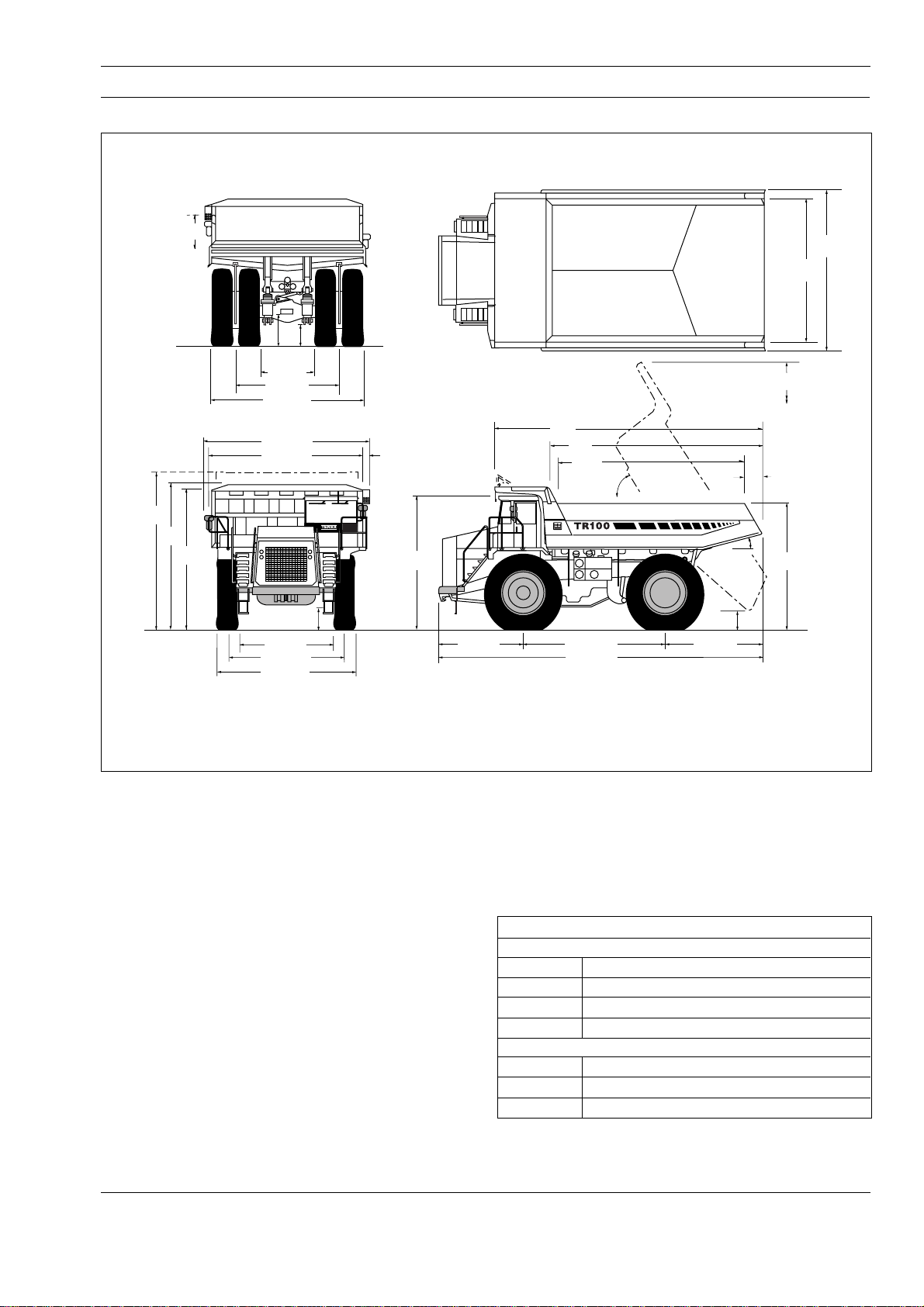
Max
Body
Depth
Optional
Spillguard
5 235
(17-2)
4 850
(15-11)
4 700
(15-5)
1 635
(5-4)
1 220
755
(4-0)
(2-7)
1 755 (5-9)
3 420 (11-3)
5 080 (16-8)
5 935 (19-6)
4 825 (15-10)
GENERAL INFORMATION - TR100 Mining Truck
Section 000-0000
SM - 2034
5 150
(16-11)
4 730
(15-6)
8 960
(29-5)
510
(1-8)
15˚
4 445
(14-7)
275
(0-11)
Vehicle Clearance Diameter (SAE) 24.5 m (80 ft)
4 575
(15-0)
8 640
(28-4)
6 880
(22-7)
(19-11)
6 080
58˚
815 (2-8)
2 945 (9-8)
3 760 (12-4)
4 570 (15-0)
3 150 (10-4)
Fig. 1 - Machine Dimensions
ENGINE
Make/Model ..................................Cummins KTA-38-C1050
Type .............................. 4 Cycle, Turbocharged/Aftercooled
Gross Power
at 2 100 rev/min.................. 783 kW (1 050 hp, 1 094 PS)
Net Power at 2 100 rev/min ..........727 kW (975 hp, 988 PS)
Note: Power ratings to SAE J1995 June 1990. Net Power
is after deductions for fan and alternator. Engine requires
no derating up to 3 050 m (10 000 ft) altitude.
Maximum Torque .............................. 4 631 Nm (3 415 lbf ft)
at 1 300 rev/min
Number of Cylinders/Configuration ................................12V
Bore x Stroke ........................159 x 159 mm (6.25 x 6.25 in)
Total Displacement ..............................37.7 litres (2 300 in³)
Starting...................................................................... Electric
Maximum Speed, Full Load ............................ 2 100 rev/min
Maximum Speed, No Load ............................. 2 400 rev/min
Idle Speed.......................................................... 750 rev/min
Safe Operating Angle .................................. 30°/60% Grade
660 (2-2)
4 570 (15-0)
10 820 (35-6)
3 100 (10-2)
Dimensions in mm (ft-in)
TRANSMISSION
Make/Model ........................................Allison DP-8963 CEC
Automatic electronic control with soft shift feature.
Remote mounted in the frame with integral TC 890 torque
converter and planetary gearing. Six speeds forward, one
reverse. Automatic converter lockup action in all speed
ranges. Downshift inhibitor. Hydraulic retarder.
Speeds With Standard Planetary
Forward
Gear 1 2 3 4 5 6
Ratio 4.24 2.32 1.69 1.31 1.00 0.73
km/h 8.2 15.0 20.6 26.5 34.8 47.6
mile/h 5.1 9.3 12.8 16.5 21.6 29.6
Reverse
Ratio 5.75
km/h 6.0
mile/h 3.8
SM 1618 Rev 1 11-00
1

General Information - TR100 Mining Truck
Section 000-0000
DRIVE AXLE
Heavy duty axle with full floating axle shafts, single
reduction spiral bevel gear differential and planetary
reduction at each wheel.
Ratios: Standard Optional
Differential.............................................2.16:1 2.16:1
Planetary.............................................13.75:1 10.50:1
Total Reduction...................................29.70:1 22.68:1
SUSPENSION
Front: King pin strut type independent front wheel
suspension by self-contained, variable rate, nitrogen/oil
cylinders.
Rear: Variable rate nitrogen/oil cylinders with A-frame
linkage and lateral stabilizer bar.
Maximum Strut Stroke
Front ....................................................... 235 mm (9.25 in)
Rear .......................................................... 175 mm (6.9 in)
Maximum Rear Axle Oscillation..................... ± 7.0 Degrees
WHEELS AND TYRES
Wheel Rim Width ....................................................... 19.5 in
Tyres (Front & Rear)
Standard .............................................27.00 R 49** Radial
Optional ........................................... 27.00-49 (48 PR) E-4
Note: It is recommended that for tyres both listed and
unlisted, the user should consult the tyre manufacturer and
evaluate all job conditions in order to make the proper
selection.
BRAKES
Service
All hydraulic brake system. Transmission mounted pressure
compensating pump provides hydraulic pressure for brakes
and steering. Independent circuits front and rear. Each
circuit incorporates a nitrogen accumulator which stores
energy to provide consistent braking response.
Front Brake Circuit Pressure ............. 159 bar (2 300 lbf/in²)
Rear Brake Circuit Pressure ....................52 bar (750 lbf/in²)
Accumulators:
Nitrogen Precharge Pressure ...............55 bar (800 lbf/in²)
Front:
Type..............................Dry Disc with 1 calliper per wheel
Disc Diameter ............................................965 mm (38 in)
Pad Area, Total.................................... 2 015 cm²
(320 in²)
Parking
Application of rear brakes by springs in brake disc pack.
Hydraulically released.
Hold-off Pressure ..................................83 bar (1 200 lbf/in²)
Retardation
Modulated lever control of rear disc pack.
Retarder Actuation Pressure ......... up to 33 bar (480 lbf/in²)
Emergency
Push button solenoid control applies service and parking
brakes. Automatically applies when engine is switched off.
Parking brake applies should system pressure fall below a
predetermined level.
Brakes conform to ISO 3450, SAE J1473 OCT 90.
STEERING SYSTEM
Independent hydrostatic steering with closed-centre
steering valve, accumulator and pressure compensating
piston pump.
Accumulator provides uniform steering regardless of engine
speed. In the event of loss of engine power it provides
steering of approximately two lock-to-lock turns.
A low pressure indicator light warns of system pressure
below 83 bar (1 200 lbf/in²). Steering conforms to ISO 5010,
SAE J53.
System Pressure................................ 159 bar (2 300 lbf/in²)
Relief Pressure ...................................207 bar (3 000 lbf/in²)
Steering Cylinders ................... Double Acting, Single Stage
Accumulator:
Oil Capacity ................................. 16.4 litres (4.33 US gal)
Nitrogen Precharge Pressure ...............55 bar (800 lbf/in²)
Steering Angle (Left and Right) .......................................39°
Pump:
Type......................................................................... Piston
Capacity at 2 100 rev/min....... 2.0 litres/s (32 US gal/min)
BODY HYDRAULICS
Two body hoist cylinders are mounted between the frame
rails. Cylinders are two-stage with power down in the
second stage.
System Relief Pressure ..................... 190 bar (2 750 lbf/in²)
Pump:
Type........................................................................... Gear
Capacity at 2 100 rev/min....... 6.1 litres/s (97 US gal/min)
Control Valve ...................... Servo Controlled, Open Centre
Body Raise Time............................................. 16.3 Seconds
Body Lower Time ............................................... 18 Seconds
Rear:
Type............................... Oil cooled, multiple friction discs,
completely sealed from dirt and water.
Braking Surface, Total ..................87 567 cm² (13 573 in²)
2
ELECTRICAL
Type ............................................. 24 Volt, Negative Ground
Battery......... Four, 12 Volt, 210 Ah each, Maintenance Free
Accessories................................................................ 24 Volt
Alternator ..................................................................70 Amp
Starter ............................................................... Two, 8.9 kW
SM 1618 Rev 1 11-00

General Information - TR100 Mining Truck
Section 000-0000
BODY
Longitudinal 'V' type floor with integral transverse boxsection stiffeners. The body is exhaust heated and rests on
resilient impact absorption pads.
Body wear surfaces are high hardness (360-440 BHN)
abrasion resistant steel. Yield strength of plates 1 000 MPa
(145 000 lbf/in²).
Plate Thicknesses:
Floor ......................................................... 19 mm (0.75 in)
Side .......................................................... 10 mm (0.39 in)
Front, lower...............................................10 mm (0.39 in)
ROPS Cabguard SAE J1040 Feb 86. ISO 3471
Volumes:
Struck (SAE)......................................... 41.6 m³ (54.4 yd³)
Heaped 2:1 (SAE) ................................ 57.0 m³ (74.5 yd³)
TYPICAL NOISE LEVELS
OPERATOR EAR (ISO 6394) ....................................83 dbA
*EXTERIOR SOUND RATING
(SAE J88 JUN 86)...................................................... 93 dbA
*The above result is for the mode giving the highest exterior
sound level when measured and operated as per the
prescribed procedures of the standard. Results shown are
for the unit in base configuration.
Note: Noise Level Exposure to the operator and bystander
personnel may be higher depending upon proximity to
buildings, rock piles, machinery etc.. The actual job site
Noise Level Exposure must be measured and applicable
regulations complied with in respect to Employee Hearing
Protection.
SERVICE CAPACITIES
Engine Crankcase and Filters.......... 134 litres (35.4 US gal)
Transmission and Filters..................... 100 litres (26 US gal)
Cooling System................................ 304 litres (80.3 US gal)
Fuel Tank ....................................... 1 090 litres (288 US gal)
Steering Hydraulic Tank .................... 61 litres (16.1 US gal)
Steering System.................................... 72 litres (19 US gal)
Body and Brake Cooling Tank ......... 297 litres (78.5 US gal)
Body and Brake Cooling System ...... 564 litres (149 US gal)
Planetaries (Total) ............................. 57 litres (15.1 US gal)
Differential.......................................... 61 litres (16.1 US gal)
Front Ride Strut (Each) ........................ 27 litres (7.1 US gal)
Rear Ride Strut (Each)......................... 18 litres (4.8 US gal)
Power Takeoff........................................ 4 litres (1.1 US gal)
Air Conditioning Compressor ...... 0.135 litres (0.036 US gal)
VEHICLE WEIGHTS (MASS)
kg lb
Chassis, with hoists 53 240 117 380
Body, standard 15 380 33 900
Net Weight 68 620 151 280
PAYLOAD, maximum 90 720 200 000
Maximum Gross Weight* 159 340 351 280
FOR UNIT EQUIPPED WITH OPTIONAL BODY LINER
PLATES:
Chassis, with hoists 53 240 117 380
Body, with wear plates 20 910 46 100
Net Weight 74 150 163 480
PAYLOAD, maximum 85 190 187 800
Maximum Gross Weight* 159 340 351 280
* Maximum permissible gross vehicle weight with options,
attachments, full fuel tank and payload.
WEIGHT DISTRIBUTION Front Axle Rear Axle
Empty % 49 51
Loaded % 34 66
SM 1618 Rev 1 11-00
* * * *
3

THIS PAGE IS INTENTIONALLY LEFT BLANK
CHASSIS - Chassis, Hood and Fenders
Section 100-0010
SM - 1585
1
2
7
13
12
11
8
5
4
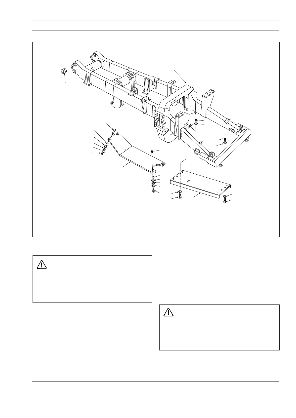
1 - Frame Assembly
2 - Bushing
3 - Engine Guard
4 - Transmission Guard
5 - Nut
6 - Hardened Washer
7 - Bolt
Fig. 1 - Exploded View of Chassis and Guards
REMOVAL
WARNING
To prevent personal injury and property
damage, be sure wheel chocks, blocking
materials and lifting equipment are properly
secured and of adequate capacity to do the job
safely.
10
6
10
5
13
12
11
8
7
6
9
8 - Hardened Washer
9 - Bolt
10 - Nut
3
6
6
9
11 - Spring Disc
12 - Hardened Washer
13 - Hardened Spacer
3. Attach a suitable lifting device to the component
and remove mounting hardware. Remove the
component from the vehicle.
INSTALLATION
Note: Tighten all fasteners to standard torques listed
in Section 300-0080, STANDARD BOLT AND NUT
TORQUE SPECIFICATIONS.
To remove any of the components shown in
Figs. 1 through 6 (or similar components) the
following procedures should be carried out.
1. Position the vehicle in a level work area, apply the
parking brake and switch off the engine.
2. Turn steering wheel several times to relieve
pressure in the steering circuit. Block all road
wheels.
SM 1622 12-98
WARNING
To prevent personal injury and property
damage, be sure wheel chocks, blocking
materials and lifting equipment are properly
secured and of adequate capacity to do the job
safely.
Using a suitable lifting device, align the component to
be installed in position on the chassis. Secure the
component securely to the chassis with mounting
hardware removed during removal.
1
 Loading...