

Terex TL80, TL100 Operating Instructions Manual
OPERATING INSTRUCTIONS
Language version: EN
Edition: 2010-07
Order number: 5780211303
From vehicle ID No.:
Translation of the original operating instructions
tl80
Wheel Loader
tl80
Wheel Loader

Terex GmbH
Geschäftsbereich Terex
|Schaeff
Schaeffstr. 8
74595 Langenburg
Germany
Phone +49(0)7905/58-0
Fax +49(0)7905/58-114
www.terex.com
E-mail: info@terex.com
Please complete before commissioning the wheel loader:
Vehicle model: ..........................................................................
Vehicle ID No.: ..........................................................................
Year of construction: ...............................................................
Commissioned on: ...................................................................
Dealer:
This operating manual is protected by limited copyright. It may be reproduced for and used by the drive /
plant operator.

Table of Contents
TL80
1 Introduction...................................................................................................................................1
1.1 Warranty and Maintenance.......................................................................................................................2
1.2 Copyright...................................................................................................................................................2
1.3 Notes on using the Operating Instructions................................................................................................2
1.4 Environmental standards..........................................................................................................................3
1.5 Pictograms................................................................................................................................................3
1.6 Location of safety signs ............................................................................................................................5
2 Safety and Accident Prevention..................................................................................................7
2.1 Introductory remarks.................................................................................................................................7
2.2 Intended use .............................................................................................................................................8
2.3 General safety notes.................................................................................................................................9
2.4 Operation ..................................................................................................................................................9
2.5 Danger zone............................................................................................................................................10
2.6 Transport of persons...............................................................................................................................10
2.7 Stability....................................................................................................................................................10
2.8 Travel operation......................................................................................................................................11
2.9 Working Operation..................................................................................................................................11
2.10 Guides...................................................................................................................................................12
2.11 Danger of falling objects .......................................................................................................................12
2.12 Working in the vicinity of underground power lines ..............................................................................12
2.13 Working in the vicinity of overhead power lines....................................................................................13
2.14 Operation in closed rooms....................................................................................................................13
2.15 Work stoppages....................................................................................................................................13
2.16 Change of work attachments, maintenance, repair..............................................................................14
2.17 Recovery, loading, transportation.........................................................................................................15
2.18 Monitoring and inspections...................................................................................................................15
2.19 Fire prevention......................................................................................................................................16
2.20 Emergency exit .....................................................................................................................................16
2.21 Other dangers.......................................................................................................................................16
3 Technical data.............................................................................................................................17
3.1 Views.......................................................................................................................................................17
3.2 Diesel engine ..........................................................................................................................................25
3.3 Electrical system.....................................................................................................................................25
3.4 Transmission...........................................................................................................................................25
3.5 Brakes.....................................................................................................................................................26
3.6 Hydraulic system.....................................................................................................................................26
3.7 Axles .......................................................................................................................................................27
3.8 Tires ........................................................................................................................................................27
3.9 Consumables..........................................................................................................................................28
3.9.1 Filling quantities................................................................................................................................28
3.9.2 Consumable specifications...............................................................................................................29
3.10 Permissible loads in compliance with German Road Traffic Regulations (StVZO)..............................31
3.11 Sound level values, vibration................................................................................................................31
3.11.1 Equivalent vibration values................................................................................................................31
3.12 Dimensions and weights.......................................................................................................................32
3.13 Front loader installation.........................................................................................................................33
3.14 Bucket...................................................................................................................................................33
3.15 Fork lift attachment................................................................................................................................34
3.16 Optional accessories (options)..............................................................................................................35
4 Operation.....................................................................................................................................37
4.1 First Instruction........................................................................................................................................37
4.2 Display elements and operating controls................................................................................................38
4.3 Engine.....................................................................................................................................................42
4.3.1 Starting the engine...........................................................................................................................42
4.3.2 Monitoring during operation..............................................................................................................43
4.3.3 Switching off the engine...................................................................................................................43
4.4 Driver's seat / Steering wheel tilt adjustment..........................................................................................44
4.5 Heating / ventilation.................................................................................................................................45
4.6 Lighting in compliance with German Road Traffic Regulations (StVZO)................................................46
4.7 Hydroinflation of tires ..............................................................................................................................46

Table of Contents
TL80
4.8 Driving, steering and braking..................................................................................................................47
4.8.1 Driving ..............................................................................................................................................47
4.8.2 Steering............................................................................................................................................49
4.8.3 Brakes ..............................................................................................................................................49
4.8.4 Driving on roads ...............................................................................................................................50
4.8.5 Switching off the machine (parking).................................................................................................51
5 Working Operation of the machine ...........................................................................................53
5.1 General notes..........................................................................................................................................53
5.1.1 Lever controls.......................................................................................................................................53
5.2 Operation - Loader..................................................................................................................................54
5.3 Changing work attachments ...................................................................................................................56
5.3.1 General notes...................................................................................................................................56
5.3.2 Assembly of work attachments.........................................................................................................57
5.4 Notes on how to work with the machine .................................................................................................59
5.4.1 Loading.............................................................................................................................................59
5.4.2 Scraping and grading .......................................................................................................................59
5.4.3 Excavating........................................................................................................................................59
6 Recovery and transport of the machine ...................................................................................61
6.1 Recovery of the machine........................................................................................................................61
6.2 Loading the machine using a crane........................................................................................................62
6.3 Transporting the machine.......................................................................................................................62
7 Maintenance and Care................................................................................................................63
7.1 General notes..........................................................................................................................................63
7.2 Intervals...................................................................................................................................................63
7.3 Regular oil analysis.................................................................................................................................64
7.4 Warranty..................................................................................................................................................64
7.5 Inspection parts and aids........................................................................................................................65
7.6 Care and cleaning...................................................................................................................................66
7.7 Notes for winter operation.......................................................................................................................66
7.8 Checking, maintenance and inspection plans ........................................................................................68
7.8.1 Initial inspection (hand-over inspection)...........................................................................................68
7.8.2 Daily and weekly tasks.....................................................................................................................70
7.8.3 Overview of lubricating points ..........................................................................................................72
7.8.4 Inspection plan .................................................................................................................................74
7.9 Inspection and maintenance work ..........................................................................................................76
7.9.1 Engine oil..........................................................................................................................................76
7.9.2 Engine oil filter..................................................................................................................................77
7.9.3 Cooling system - combined hydraulic oil-water cooler.....................................................................78
7.9.4 Fuel system......................................................................................................................................80
7.9.5 Air filter, air intake.............................................................................................................................82
7.9.6 V-belt................................................................................................................................................85
7.9.7 Checking Valve Lash........................................................................................................................85
7.9.8 Brakes ..............................................................................................................................................86
7.9.9 Hydraulic oil tank..............................................................................................................................87
7.9.10 Hydraulic oil cooler.........................................................................................................................88
7.9.11 Hydraulic oil filter............................................................................................................................89
7.9.12 Breather..........................................................................................................................................90
7.9.13 Axles...............................................................................................................................................91
7.9.14 Wheels............................................................................................................................................93
7.9.15 Injection valves...............................................................................................................................94
7.9.16 Control cog belt for drive motor......................................................................................................94
7.9.17 Electrical equipment.......................................................................................................................94
7.9.18 Cab ventilation dust filter................................................................................................................95
7.9.19 Windshield washer system.............................................................................................................95
7.10 Taking out of service.............................................................................................................................96
7.10.1 Preservation for temporary taking out of service............................................................................96
7.10.2 During immobilization.....................................................................................................................96
7.10.3 After the machine had been taken out of service...........................................................................96
7.10.4 Disposing of the wheeled loader....................................................................................................96

Table of Contents
TL80
8 Troubleshooting..........................................................................................................................97
8.1 General notes..........................................................................................................................................97
8.2 Engine.....................................................................................................................................................97
8.3 No steering movement............................................................................................................................97
8.4 Insufficient performance of service brake...............................................................................................97
8.5 Insufficient performance of parking brake...............................................................................................97
8.6 Hydrostatic travel drive without neutral position .....................................................................................97
8.7 Hydraulic oil exceeds max. admissible temperature...............................................................................98
8.8 Sluggish acceleration and deceleration, too little propulsive power.......................................................98
8.9 Transmission works in one direction only...............................................................................................99
8.10 Transmission works in neither direction................................................................................................99
8.11 Loader installation is not working..........................................................................................................99
8.12 Decrease in machine's performance (loader installation)...................................................................100
8.13 Working cylinders not operating satisfactorily.....................................................................................100
8.14 Faults in the electrical system.............................................................................................................100
9 Appendix....................................................................................................................................101
9.1 Electrical system...................................................................................................................................101
9.2 Equipment options ................................................................................................................................102
9.3 Immobilizer............................................................................................................................................103
9.3.1 Activating the immobilizer...............................................................................................................103
9.3.2 Deactivating the immobilizer ..........................................................................................................103
9.3.3 Learning a new key........................................................................................................................103
9.3.4 Learning multiple new keys............................................................................................................104
9.3.5 Clearing learned keys.....................................................................................................................104
9.3.6 Security functions...........................................................................................................................104
9.3.7 Fault causes...................................................................................................................................105

Table of Contents
TL80
Introduction 1
TL80 1
1 Introduction
You decided to buy a Terex TL80 Wheel Loader.
The confidence placed in this model will be
rewarded by the efficient and economical
performance of the machine.
This operating manual contains all the information
and instructions that are required to handle the
machine correctly. Please read them carefully
before putting the machine into operation and
make sure that they are kept at hand at all times.
Should you need further explanations or should
anything be unclear, please contact your dealer
immediately.
Special equipment and attachments are not
included in these Operating Instructions.
We reserve the right to make improvements on the
machine within the scope of impending technical
developments, without incurring any obligation to
change these Operating Instructions.
Any modifications of Terex products and
their equipment using extras and work
attachments which are not included in
our product range require our written
approval. If our approval is not sought,
our warranty expires, as does our
product liability.
Please state the vehicle type and vehicle
identification number when making inquiries or
orders, and in all written correspondence.
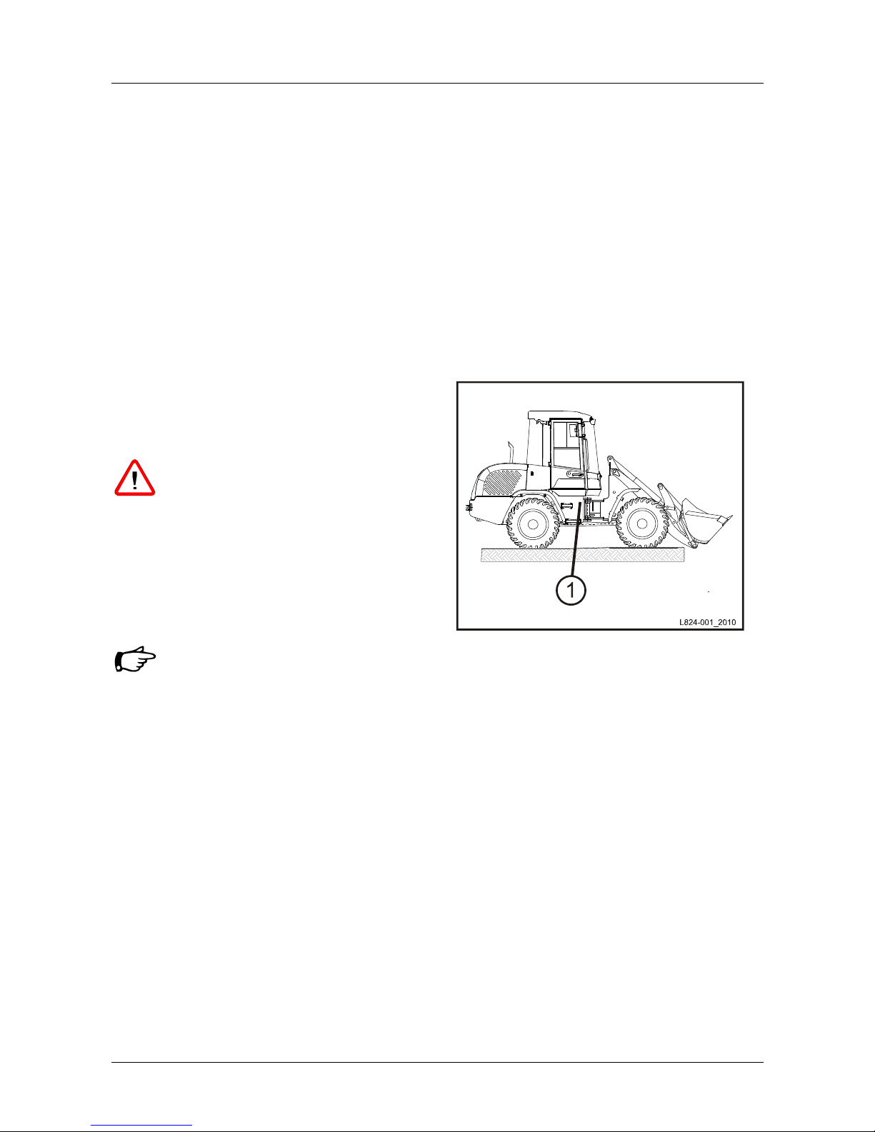
The vehicle identification number of
the machine is stamped onto the type
label (1/1).
Fig. 1 Type label
1 Introduction
2 TL80
1.1 Warranty and Maintenance
The warranty period covers 12 months, beginning
with the day the machine is handed over or put into
operation.
Safe working conditions and good working order of
the machine are prerequisites for efficient work.
Your Terex wheel loader fulfils these requirements
when correctly handled and when serviced and
maintained as specified.
Careful observation of the machine whilst in
function and the use of the specified fuels,
lubricants, and coolants will prevent malfunction.
Trained specialist personnel are responsible for
any servicing of the machine which requires expert
knowledge. Inspections and repairs must therefore
be carried out by your dealer’s customer service.
In respect of possible claims for damages during
the warranty period, all work specified in the
maintenance and inspection plan must be carried
out at the specified intervals.
After the warranty period, too, regular maintenance
must be performed in order to ensure that the
machine is constantly in good working order and
enjoys a reasonable service life.
Insist that only original Terex spare parts are
used in the event of any repair work. In this way,
you will have a product of lasting high quality,
thereby ensuring that your machine maintains its
original condition.
1.2 Copyright
This instruction book is intended for use by
personnel responsible for operation, maintenance,
repair and supervision of the machine.
This operating manual is copyrighted. It contains
technical specifications and documentation which
shall not, either in whole or in part, be reproduced,
transmitted or used for the purpose of competition
without our express permission.
1.3 Notes on using the Operating Instructions
References to pictures and items
The references to pictures and items contained in
the text, such as (Fig. 12/4) or (12/4) mean figure
12, item 4.
The figures shown in this manual partly contain
additional equipment.
Symbol "Danger "
This symbol indicates a high risk of
injuries. Strictly observe the safety
instructions.
Symbol "Warning "
Not abiding by the information indicated
by this symbol might cause substantial
property or equipment damage. Strictly
observe the safety instructions.
Symbol "Note "
This symbol is employed for information
containing important notes about the
correct use and/or how to proceed. Noncompliance may lead to malfunction.
Introduction 1
TL80 3
1.4 Environmental standards
When operating or working on the machine the
environmental standards currently valid must be
observed at all times.
During installation, repair and maintenance tasks,
particular care must be taken that substances that
would damage the environment such as
• lubricating oil and grease
• hydraulic oil
• fuel
• coolant
• cleaning fluids containing solvents
do not seep into the ground or the sewerage
system.
These substances must be kept, transported,
collected and disposed of in suitable containers.
If above-mentioned liquids seep into the ground,
their escape must be stopped immediately and the
liquid be bound with suitable binding agents. If
necessary, the soil involved must be removed.
Absorbent materials and removed soil must be
disposed of properly. The environmental standards
currently valid must be observed.
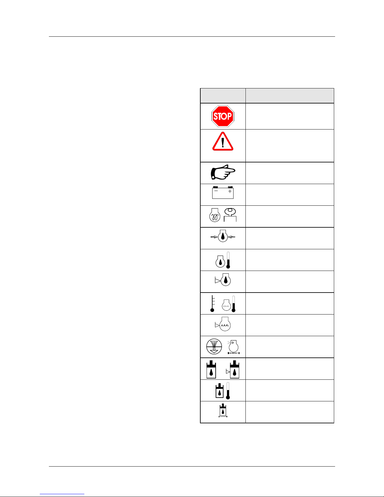
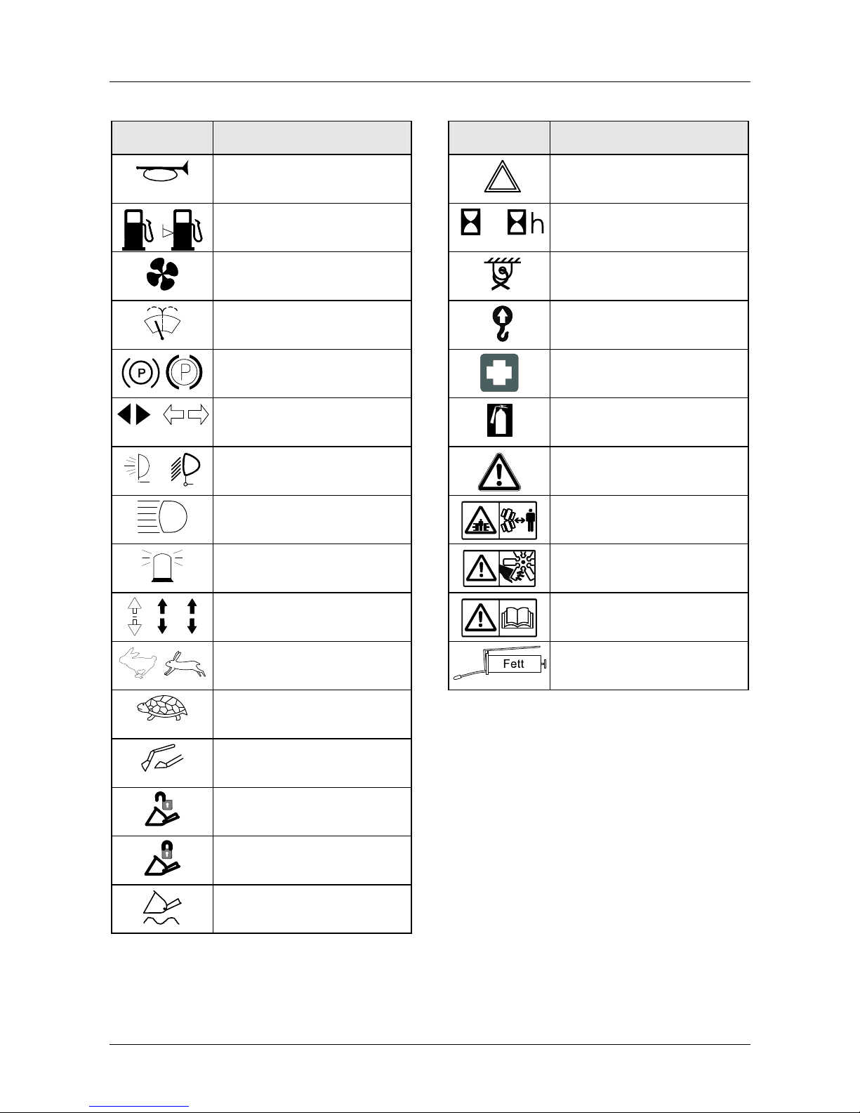
1.5 Pictograms
The following Table explains the meaning of the
pictograms which may be attached to your
machine.
Symbol Description
Danger
In Operating Instructions:
Warning
On machine:
Caution
Note
Battery charge indicator
Preheating
Engine oil pressure
Engine oil temperature
Engine oil level
Coolant temperature
Coolant level
Air filter
Hydraulic oil
Hydraulic oil level
Hydraulic oil temperature
Hydraulic oil filter clogging
indicator
1 Introduction
4 TL80
Symbol Description
Horn
Fuel
Fuel level
Blower
Heating/ventilation
Windshield washer and wiper
system
Parking brake
Direction indicator LT/RT
Working floodlights
High-beam indicator
Rotating beacon
V
R
Travel direction
FWD/REV
Travel speed
FAST
Travel speed
SLOW
Working hydraulics shut-off
Unlocked
Locked
Float position
Symbol Description
Hazard warning system
Operating mode indicator
Operating hours
Lashing points
Suspension points for loading
by crane
First-aid kit
Fire extinguisher
On machine:
Safety distance
Danger of crushing
Danger of injury
The relevant notes in the
operating instructions should
be observed
Grease gun
Lubricating point
Introduction 1
TL80 5
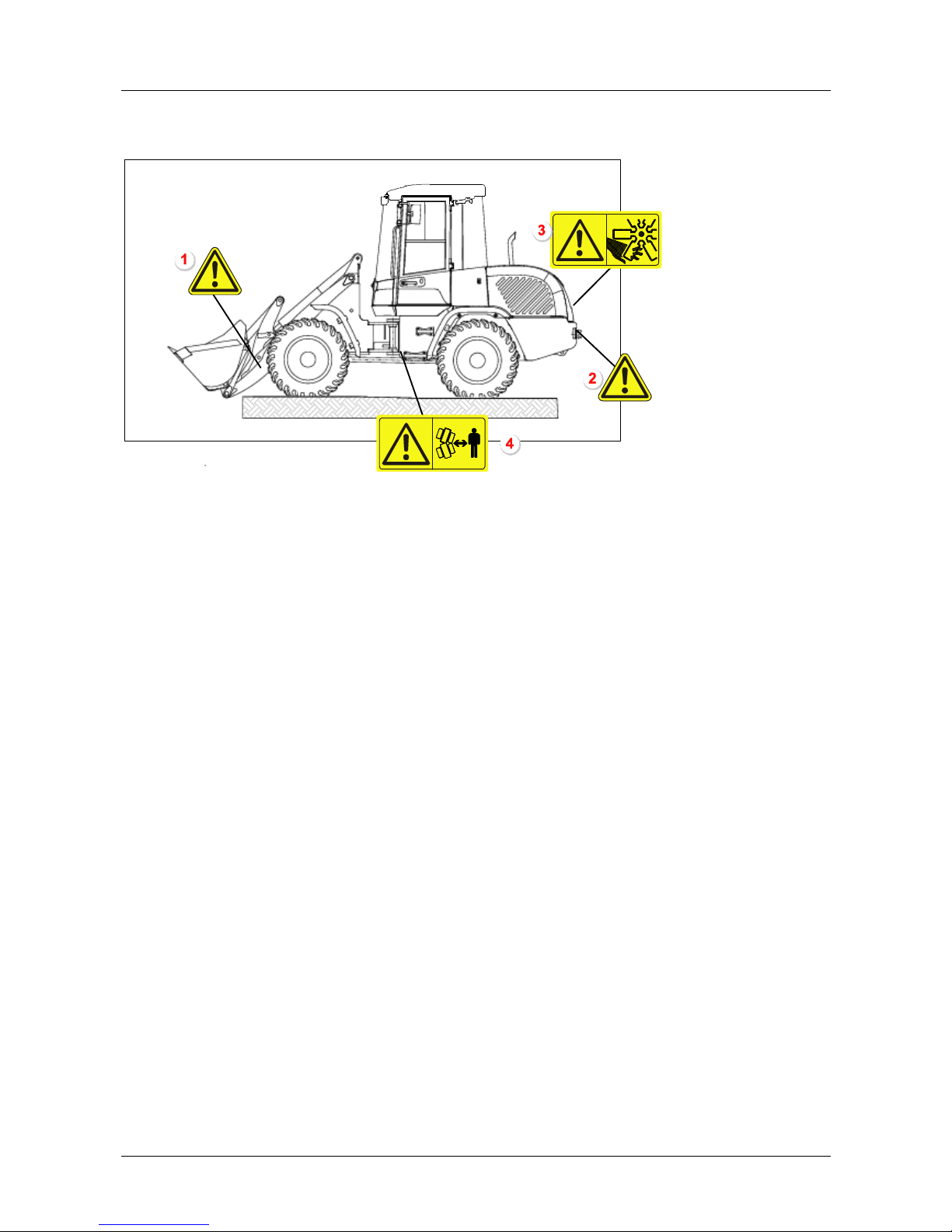
1.6 Location of safety signs
The safety signs are located in the following positions on the machine:
Locations of safety signs
1 Safety distance (left and right sides of lifting frame)
2 Safety distance
3 Danger of injury
4 Danger of crushing
Servicing and replacing safety signs
- The safety of the operator always has to come first.
- Safety signs must always be kept in good condition and legible.
- Replace any safety sign which has been damaged or disappeared.
- Use mild detergents and water to clean the safety signs.
- Do not use any detergents containing solvents.
- Always specify machine serial number and language when ordering safety signs.

6 TL80

Safety and Accident Prevention 2
TL80 7
2 Safety and Accident Prevention
2.1 Introductory remarks
Declaration of Conformity
The machine complies with the
fundamental requirements stipulated in
the applicable European guidelines.
Conformity has been proven. The
respective documents and the original of
the Certificate of Conformity are kept by
the manufacturer.
A copy of the Certificate of Conformity is
attached to the sales documents.
EC declaration of conformity
according to the machinery directive 2006/42/EC
1. We hereby declare that the earth-moving machine of type TL 80:
Wheel Loader: TL80
Vehicle ID No.:TL0802
Actual productivity: 44 KW
2. complies with the following applicable regulations:
2006/42/EC, 2004/108/EC (EMC), RL 2000/14/EC Appendix VIII (noise emission)
3. Representative sound power level:
100,0 dB (A)
4. Guaranteed sound power level:
101 dB (A)
5. Applied harmonized standards:
EN ISO 12100-2
6. Applied European standards:
EN 474-1
EN 474-3
7. Document editor, who is authorized to compile technical documentation:
Maik Schulze, D 74564 Crailsheim, Kraftwerkstraße 4, Germany
8. Voluntary type examination performed as well as certification in accordance with RL 2000/14/EC
Appendix VIII at:
Fachausschüsse Bau (BAU) und Tiefbau (TB)
Prüf- und Zertifizierungsstelle im BG-PRÜFZERT
80687 Munich, Germany
The EC declaration of conformity only applies if the earth-moving machine is used in accordance with the
operating instructions. It includes the use of original Terex work attachments and other work attachments,
which are mentioned in the operating instructions or in other Terex documentation for application at this earthmoving machine.
Replaceable equipment manufactured by Terex or third party manufacturers may only be installed and used if
the installation at the affected earth-moving machine is performed by Terex. In all other cases, special written
approval is required from Terex.
Date of the declaration of conformity 29.12.2009
Langenburg
Terex GmbH
Geschäftsbereich Terex Schaeff
Schaeffstraße 8
74595 Langenburg, Germany

2 Safety and Accident Prevention
8 TL80
Read the operating instructions thoroughly and
follow the notes on safe operation before putting
the earth-moving machine into operation.
National safety regulations - e.g. the Accident
Prevention Regulations, "Earth-Moving Machinery"
(BGR 500 Chapter 2.12) and "Vehicles" (BGV
D29) in the Federal Republic of Germany - must
also be complied with when operating the earthmoving machine.
In addition to the Operating Instructions, legal
regulations governing road traffic and road safety
measures must also be observed. Such duties
could also apply in respect of e.g. handling
hazardous goods or the wearing of personal safety
gear.
Furthermore, safety laws governing work in
particular locations (tunnels, adits, quarries,
pontoons, contaminated areas, etc.) must likewise
be observed.
2.2 Intended use
The earth-moving machine with standard bucket
equipment is intended solely for work which is
suitable for the function of the machine and its
work implements.
Such work involves loosening, taking up,
transporting and dumping soil, rock or other
materials as well as loading these materials on
trucks, conveyor belts or other means of transport,
when the transport of the material is normally done
by positioning the earth-moving machine.
The assembly of special work attachments such as
multi-purpose bucket, side-dump bucket, broom,
fork lift attachment etc. allows the machine to
perform the corresponding applications.
Any usage above and beyond that specified here,
e.g. the transport of persons or the usage of the lift
equipment as work platform is regarded as
improper use. The supplier cannot be held
responsible for any damage resulting from
improper use. This risk is borne solely by the user.
Strict compliance with the operating and
maintenance instructions and the performance of
maintenance work, as well as adherence to the
maintenance intervals is also part of intended use.

Safety and Accident Prevention 2
TL80 9
2.3 General safety notes
• It is important to refrain from any working
methods which impair safety.
• The earth-moving machine is only to be used if
it is in a safe, operational condition.
• The manufacturer’s instructions must be
complied with for operation, maintenance,
repair, assembly, and transportation.
• The plant operator must provide additional
special safety instructions, wherever necessary,
for specific local conditions.
• The operating instructions and any information
pertaining to safety must be carefully kept in the
driver's cab.
• The operating instructions and safety notes
must be complete and fully readable.
• Safety equipment on earth-moving machines
must not be deactivated or removed.
• Protective clothing must be worn during
operation. Rings, scarves and unbuttoned
jackets are to be avoided. Protective goggles,
protective boots, helmets, gloves, reflecting
jackets, ear-muffs, etc. may be required.
• Before commencing work, information must be
obtained on first aid and possible means of
rescue (emergency ambulance, fire brigade,
helicopters).
• A check must be carried out to ensure that the
first aid box is at hand and that its contents
comply with regulations.
• Personnel must be aware of the location and
method of operation of the fire extinguishers on
the earth-moving machine as well as on-site
fire-warning and fire-fighting equipment.
• Loose parts such as tools or other accessories
must be secured to the earth-moving machine.
• Open doors, windows, covers, flaps, etc. must
be closed or secured so that they cannot slam
shut.
2.4 Operation
Earth-moving machines shall only be
independently operated and serviced by persons
who
• are physically and mentally suitable
• have been instructed in the operation or
maintenance of earth-moving machines and
have demonstrated this ability to the plant
operator
• can be expected to perform their allocated
duties reliably.
All such persons must be of the legal minimum
age.
They must be designated by the plant operator to
operate or service the earth-moving machine.
Operating equipment and controls are only to be
operated from the driver’s seat.
The earth-moving machine is only to be ascended
and entered using the entrances and surfaces
intended for this purpose.
It is the driver’s responsibility to ensure that the
operator’s stand, entrances and other surfaces of
the earth-moving machine which have to be
stepped on are free of dirt, grease, oil, ice and
snow.

2 Safety and Accident Prevention
10 TL80
2.5 Danger zone
• Nobody must be allowed to remain in the
danger zone of an earth-moving machine.
The danger zone encompasses the
area around the earth-moving machine
in which persons may be injured by
movements of the earth-moving
machine during operation, its work
implements and attachments, or by
swinging out or falling loads.
• The machine operator is only to work the earthmoving machine if nobody is in the danger
zone.
• The machine operator must give a warning
signal to persons who may be in danger.
• The machine operator must stop work with the
earth-moving machine if someone remains in
the danger zone despite the warning.
• To ensure no danger of crushing, a sufficient
safety distance (min. 0.5 m) must be kept from
solid objects, e.g. buildings, excavation slopes,
scaffolding, other machines, etc.
• If the above safety distance cannot be
maintained, the area between solid objects and
the working zone of the earth-moving machine
must be blocked off.
• If conditions are such that the machine
operator’s view of the driving and working zone
is restricted, he must be guided or the driving
and working zone must be marked by a solid
barricade.
2.6 Transport of persons
The transport of persons on the machine is
forbidden.
2.7 Stability
• The earth-moving machine must be used,
driven and operated in such a manner that its
stability against overturning is ensured at all
times.
• The machine operator must drive at speeds
which are suitable for local conditions.
• The permitted payload of the earth-moving
machine must not be exceeded.
• The earth-moving machine must remain at a
sufficient distance from the edges of quarries,
pits, mounds and slopes to ensure there is no
risk of falling.
• Earth-moving machines must be secured so
that they cannot roll or slip when in the vicinity
of excavations, shafts, ditches, pits and slopes.

Safety and Accident Prevention 2
TL80 11
2.8 Travel operation
Before putting the earth-moving machine into
operation, the driver’s seat, mirrors and operator
controls must be adjusted so as to ensure safe
working.
A safety belt (seat belt), if installed, must always be
fastened.
The windows must be clean and free of ice.
Driving tracks must be designed so as to ensure
smooth, safe operation, i.e. they must be
sufficiently wide, on ground which has as few
slopes as possible and sufficient carrying capacity.
Downhill tracks must be set out in such a way that
earth-moving machines can be safely braked.
Before driving downhill, the appropriate gear for
the terrain must be selected and the gear lever not
be moved during downhill travel (road or off-road
gear).
On steep drops and uphill gradients, the load must
be carried on the uphill side, if possible, in order to
increase stability.
Before driving downhill, the appropriate gear for
the terrain must be selected and the gear lever
shall not be moved during downhill travel (on-road
or off-road gear).
The internal dimensions of constructions must be
noted before entering underground passages,
tunnels, etc.
It is the plant operator's responsibility to ensure
that equipment such as first-aid box, warning
triangle, hazard lights are kept with the earthmoving machine according to the traffic regulations
valid in the user’s country and that the driver has
the appropriate license as required by the national
traffic laws of the country in question.
Outside areas covered by general traffic
regulations, e.g. on factory premises, traffic
regulations should be applied in the proper
manner. This should also apply with regard to
drivers’ licenses.
2.9 Working Operation
Daily before start of operation and after every
attachment change, the machine operator must
check the correct fastening of the work
attachments as well as the correct locking of the
quick-mount hitch. Work attachments are to be
carefully moved at low height. During this check
nobody must be allowed to remain in the danger
zone of the earth-moving machine.
The machine operator shall only swing the work
equipment over occupied driver’s seats, operator
consoles and workplaces of other machines when
these are protected by overhead guards (FOPS).
If a cabin does not have the required protection,
the driver of this vehicle must leave the operator’s
stand while the work equipment is being swung
overhead.
The vehicles must be loaded in such a manner as
to ensure that there is no overloading and no
material can be lost as long as the machine is
moving. The vehicle must be loaded from the
lowest possible height.
At dumping points, earth-moving machines may
only be operated if suitable measures have been
taken to prevent rolling or falling.

2 Safety and Accident Prevention
12 TL80
2.10 Guides
Guides must be easily recognizable, e.g. by means
of reflective clothing. They must remain within the
machine operator’s field of vision.
While guiding the machine, guides shall not be
given other jobs which may distract them from their
task.
2.11 Danger of falling objects
Earth-moving machines are only to be used where
there is a danger of falling objects if the operator's
stand has a canopy (FOPS). A front guard must
be employed if there is a risk of materials breaking
through into the cabin.
In front of walls e.g. of stacked materials, earthmoving machines must be positioned and operated
in such a way that the driver's seat and entry to the
driver's seat are not situated on the side facing the
wall.
Demolition work is only to be performed by earthmoving machines where there is no danger to
persons and if the machine is equipped with
canopy, cabin-mounted front guard and the
appropriate work implement.
See regulations book "Demolition work" (ZH 1/614)
published by the German TiefbauBerufsgenossenschaft (Civil Engineering
Employer’s Liability Insurance Association).
2.12 Working in the vicinity of underground
power lines
Before commencing excavating work using earthmoving machines, it must be determined whether
any underground power lines are present in the
intended working zone which may present a
danger to persons.
If underground power lines are present, their exact
position and course must be determined in
consultation with the proprietor or operator of the
lines, and the necessary safety precautions
decided and implemented.
The course of power lines in the work area must be
clearly marked, under supervision, before
commencing any excavation work. If the position of
lines cannot be determined, search ditches must
be dug - manually, if need be.
If underground power lines are encountered
unexpectedly or they or their protective covers are
damaged, the machine operator must discontinue
work immediately and notify the supervisor.

Safety and Accident Prevention 2
TL80 13
2.13 Working in the vicinity of overhead power
lines
If the earth-moving machine is being used in the
vicinity of overhead power lines and trolley wires, a
safety distance which varies depending on the
nominal voltage of the overhead line must be
maintained between the lines and the earthmoving machine and its work equipment, to
prevent current overspill. This also applies to the
distance between these lines and attached
implements or loads.
The safety distances specified below must be
complied with:
Nominal voltage in Volt Safety distance in
meters
- 1,000 V 1.0 m
more than 1 kV - 110 kV 3.0 m
more than 110 kV - 220
kV
4.0 m
more than 220 kV - 380
kV
5.0 m
nominal voltage unknown 5.0 m
In the observation of safety distances, all working
movements of earth-moving machines, e.g.
positions of the work equipment and the
dimensions of attached loads must be taken into
consideration. Uneven ground which would cause
the earth-moving machine to be inclined and thus
nearer to overhead lines must also be taken into
account.
During work in windy conditions, both overhead
lines and work equipment may swing out, thus
reducing the safety distance.
If it is impossible to maintain sufficient distance
from overhead power lines and trolley wires, the
plant operator must consult with the proprietor or
operator of the overhead lines to find other safety
precautions to prevent current overspill. Such
measures could be, e.g.
• Switching off the current
• Re-routing the overhead line
• Cabling, or
• Limiting the work zone of earth-moving
machines.
2.14 Operation in closed rooms
If earth-moving machines are to be used in closed
spaces, these areas must be sufficiently ventilated
and special regulations observed.
2.15 Work stoppages
Before rest periods and at the end of the working
day, the driver of the earth-moving machine must
park the machine on ground which has sufficient
carrying capacity and is as level as possible, and
must secure it against unintended movement.
Before rest periods and at the end of the working
day, the driver must lower the work equipment onto
the ground or secure it so that it cannot move.
The driver is not to leave the earth-moving
machine if the work equipment has not been
lowered to the ground or secured.
Earth-moving machines shall only be parked in
places where they do not present an obstacle, e.g.
on the construction site or to plant traffic. Warning
devices, e.g. triangles, warning cordons, flashing
or hazard lights are to be used if necessary.
Before leaving the operator stand, the driver must
bring all operating equipment and controls into
home position, switch off the working hydraulics
and apply the brakes.
If the driver is leaving the earth-moving machine
unattended, he must first turn off the drive motors
and ensure that they cannot be started up by
unauthorized persons (e.g. removing ignition keys).

2 Safety and Accident Prevention
14 TL80
2.16 Change of work attachments,
maintenance, repair
Earth-moving machines shall only be converted,
maintained or serviced under the guidance of a
suitable person designated by the plant operator
and following the manufacturer’s Operating
Instructions.
After every change of work attachments, the driver
must convince himself that the quick-attach system
is correctly fastened and locked.
Work on e.g.
• brake systems,
• steering systems,
• hydraulic and
• electric systems
of the machine is only to be carried out by expert
personnel specially trained in these areas.
Stability must be ensured during all type of work on
the machine at all times.
The work equipment must be secured against
movement by lowering it to the ground or
equivalent measures, e.g. cylinder supports,
trestles. With the engine running, the unprotected
articulation range of articulated loaders shall not be
entered.
When jacking up earth-moving machines, jacking
devices must be positioned so that they cannot
slip. Jacks must be positioned and applied
absolutely straight, without tilting.
Raised earth-moving machines must be supported
by suitable structures such as crosswise stacks of
planks, square timbers or steel trusses.
Stabilize the earth-moving machine that has been
lifted with the work attachment, immediately after
lifting with a supporting structure. Work under
raised machines which are only supported by their
hydraulics is forbidden.
The engine/motor(s) must be turned off prior to all
maintenance and repair work. These requirements
may only be ignored in the case of maintenance or
repair work which cannot be performed without the
engine/motor(s) running.
When performing maintenance and repair work on
the hydraulic system, the hydraulic system must be
relieved of pressure. With the engine turned off,
lower the work equipment to the ground and
actuate all hydraulic control levers until there is no
pressure in the hydraulic system.
Before working on the electrics or when performing
arc-welding on the machine, the connection to the
battery must be disconnected.
When disconnecting the battery, first the negative
pole then the positive pole must be disconnected.
The battery must be re-connected in reverse order.
During repair work around the battery, it must be
covered with insulating material. Tools should
never be placed on or near the battery.
Protective devices of moving machine parts are
only to be opened or removed after the drive has
been switched off and cannot be switched on
again by unauthorized persons. Protective devices
are e.g. engine/motor covers, doors, protective
grating, trim.
Upon completion of assembly, maintenance or
repair work, all protective devices must once more
be attached in the proper manner.
Load-bearing parts of earth-moving machines are
only to be welded following consultation with the
manufacturer and in accordance with recognized
welding principles.
Protective structures (ROPS; FOPS) are not to be
welded or drilled in any way.

Safety and Accident Prevention 2
TL80 15
Before commencing work on the hydraulic system,
the operating pressure, pilot pressure, back
pressure and pressure inside the tank must be let
off.
Alterations, such as welding of the hydraulic
system, are only to be undertaken with the
manufacturer’s permission.
Swallowing lubricants as well as long and repeated
skin contact can be hazardous to health and
should therefore be avoided. When used properly,
there is no particular danger to health. The safety
specification sheets from the mineral companies
must be observed.
Only the hoses specified by the manufacturer shall
be used.
Hydraulic hoses must be routed and assembled by
expert personnel.
In the vicinity of fuel or batteries, smoking and
naked flames are prohibited.
2.17 Recovery, loading, transportation
Earth-moving machines are only to be loaded onto
recovery vehicles if adequate towing vehicles are
used.
The tow fixing points specified by the manufacturer
must be employed.
For loading and transportation, earth-moving
machines and all necessary auxiliary equipment
must be secured against unwanted movement.
The traveling gear and crawler unit of earth-moving
machines must be sufficiently cleaned of mud,
snow and ice to ensure that ramps can be driven
up without risk of slipping.
When transporting the earth-moving machine on
trucks, flatbed trailers, or by rail, it must be
sufficiently secured with chocks and by attachment
to the lashing points.
Before setting off, the route to be taken must be
examined to determine whether the roads are wide
enough, entrances and passages under bridges
are large enough and that roads and bridges have
sufficient carrying capacity.
2.18 Monitoring and inspections
The machine must be submitted to a general
inspection according to the existing UVVregulations (Accident Prevention Regulations).
This inspection must be carried out by an expert
(e.g. machine engineer or machine foreman):
• before the machine is put into operation for the
first time and before the machine is again put
into operation after essential modifications have
been made
• at least once a year
• in the meantime, according to operating
conditions and local environments.
The results of this inspection have to be recorded
in writing and this record kept until the next
inspection takes place.
Prior to every work shift, the machine operator
must check the earth-moving machine according to
the inspection and maintenance plan.
Hydraulic hoses must be replaced as soon as the
following damage is recognized:
• Damage to the outer layer which reaches the
intermediate layer,
• Embrittled patches on the outer layer,
• Deformations when under pressure or without
pressure which differ from the original shape of
the installed hose,
• Leaks,
• Damage to hose fittings or to the connection
between the fitting and the hose.
The coolant level may only be checked after the
engine has cooled down; the cap must be turned
carefully in order to let off excess pressure.
Prior to operations, the machine operator must
check the function of the safety devices.
The machine operator must advise the supervisor
immediately - and his replacement, if there is a
change of operator - with regard to any
shortcomings.
In the event of shortcomings which jeopardize the
operating safety of the earth-moving machine, it is
not to be used until these have been eliminated.

2 Safety and Accident Prevention
16 TL80
2.19 Fire prevention
• Switch off the engine when filling the fuel tank
and take special care as long as the engine is
hot.
• Never smoke or handle open flames whilst
refueling the tank of the machine.
MTK115002
The fire extinguisher must be kept in
the cabin (operator’s stand). The fire
extinguisher symbol must be
attached.
2.20 Emergency exit
The right-hand cab door acts as an emergency
exit.
2.21 Other dangers
Failure of hydraulic system
If the hydraulic system fails because the diesel
engine is not running, the hydraulic pump is
damaged or hydraulic oil has been lost, only the
following emergency functions can still be
performed:
• manual steering (without servo assistance) and
• lower work equipment (only if ignition is
switched on).
Technical data 3
TL80 17
3 Technical data
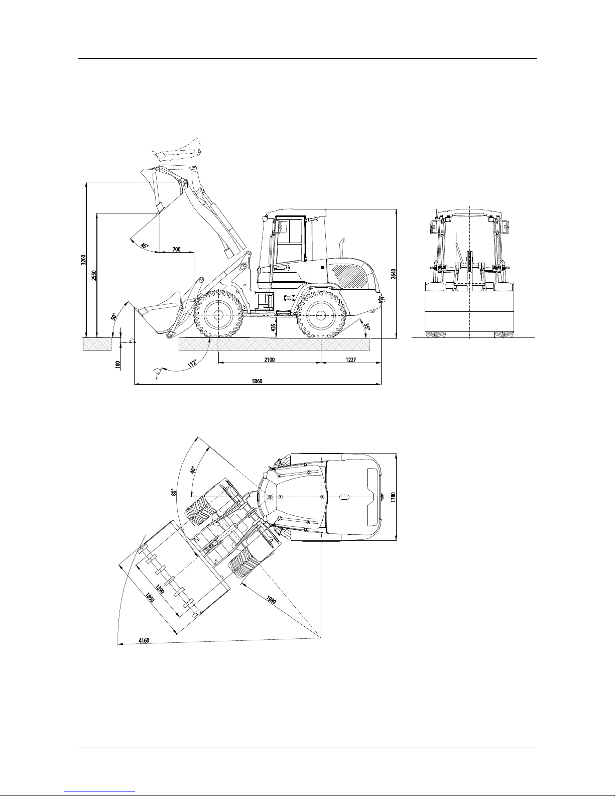
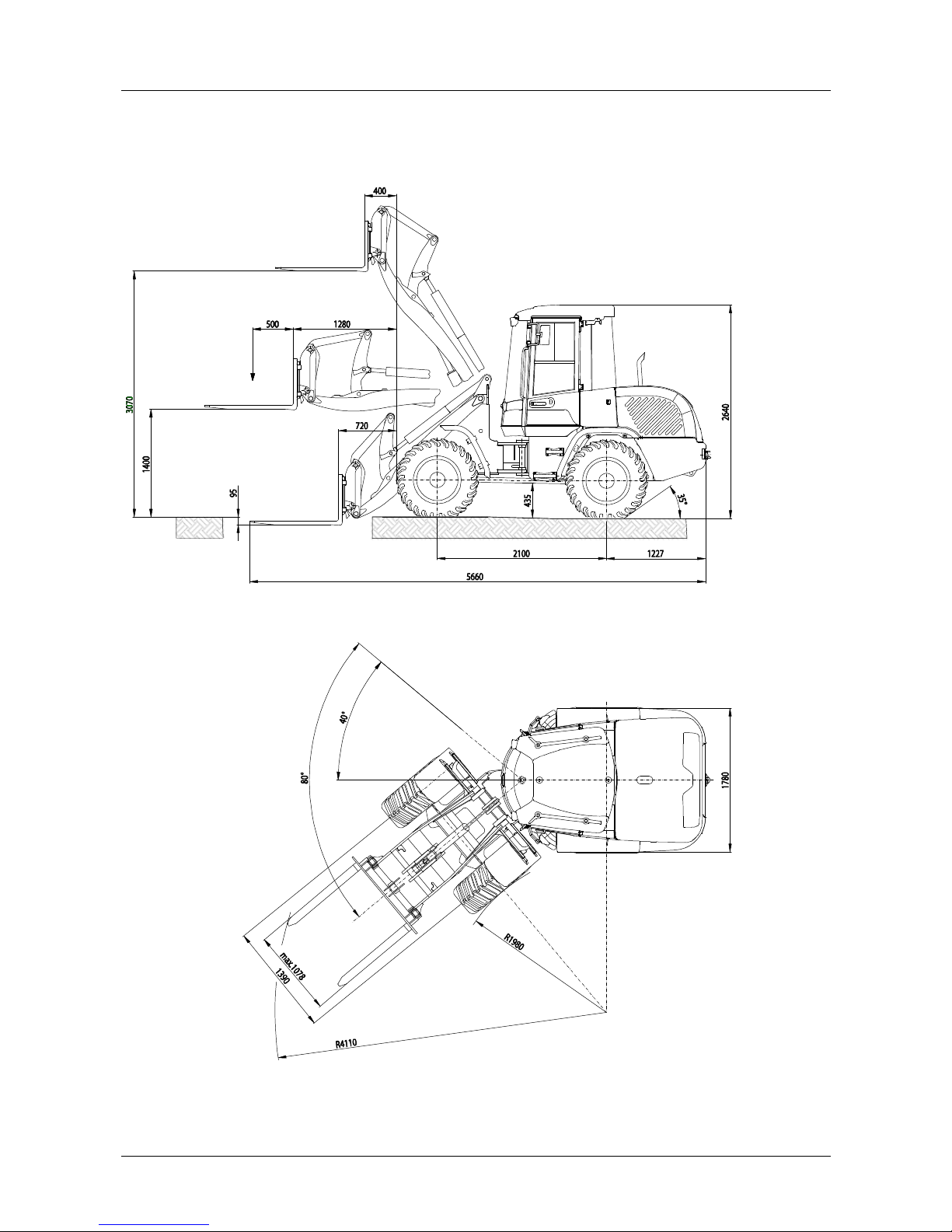
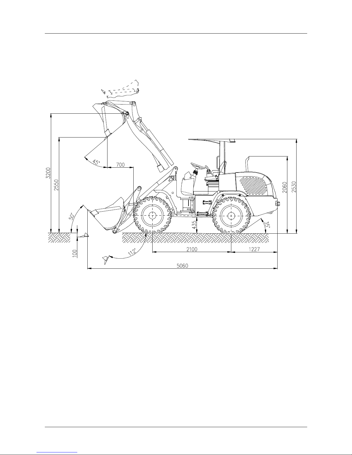
3.1 Views
• General-purpose bucket and paralell kinematics
Fig. 3 Dimensioned drawing - standard bucket and parallel kinematics
Tires 405/70 R18
3 Technical data
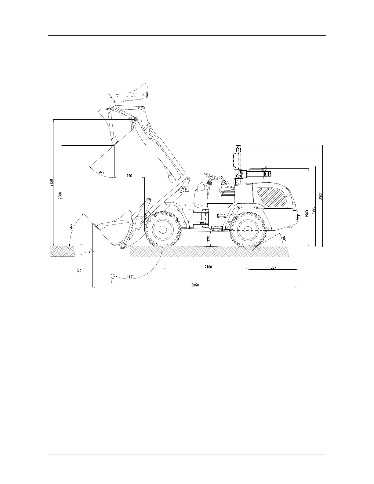
18 TL80
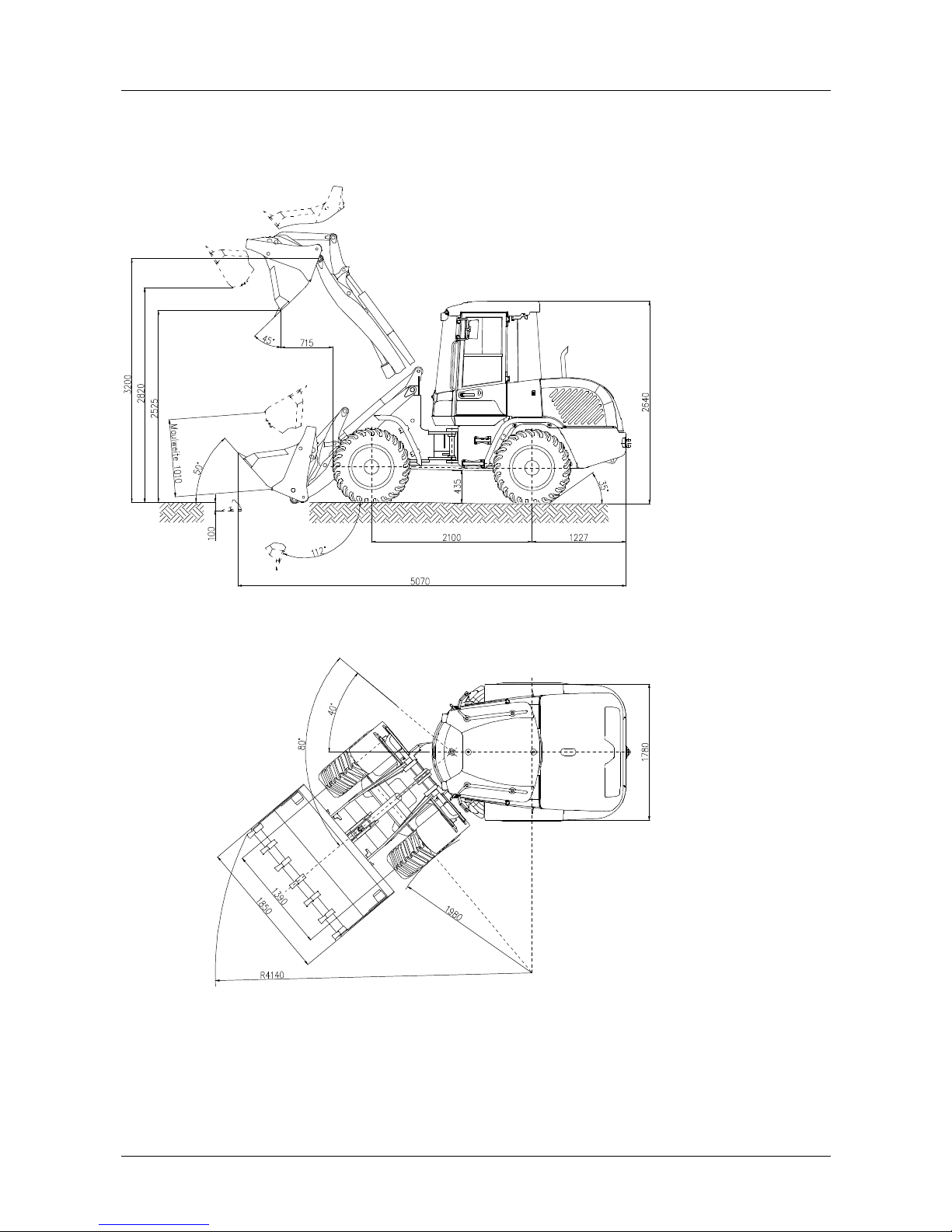
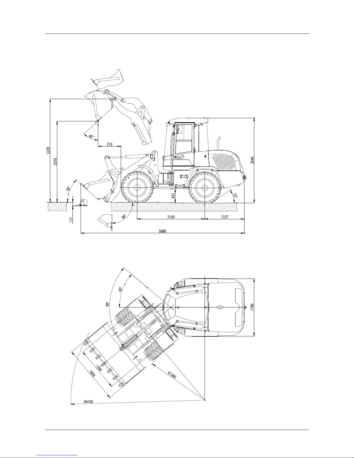
• Multi-purpose bucket and paralell kinematics
Fig. 4 Dimensioned drawing - multi-purpose bucket and parallel kinematics
Tires 405/70 R 18
Technical data 3
TL80 19
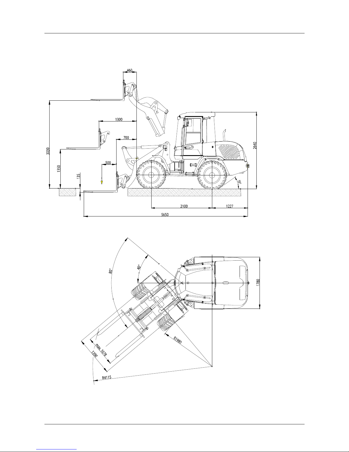
• Fork lift attachment and paralell kinematics
Fig. 5 Dimensioned drawing - fork lift attachment and parallel kinematics
Tires 405/70 R 18
3 Technical data
20 TL80
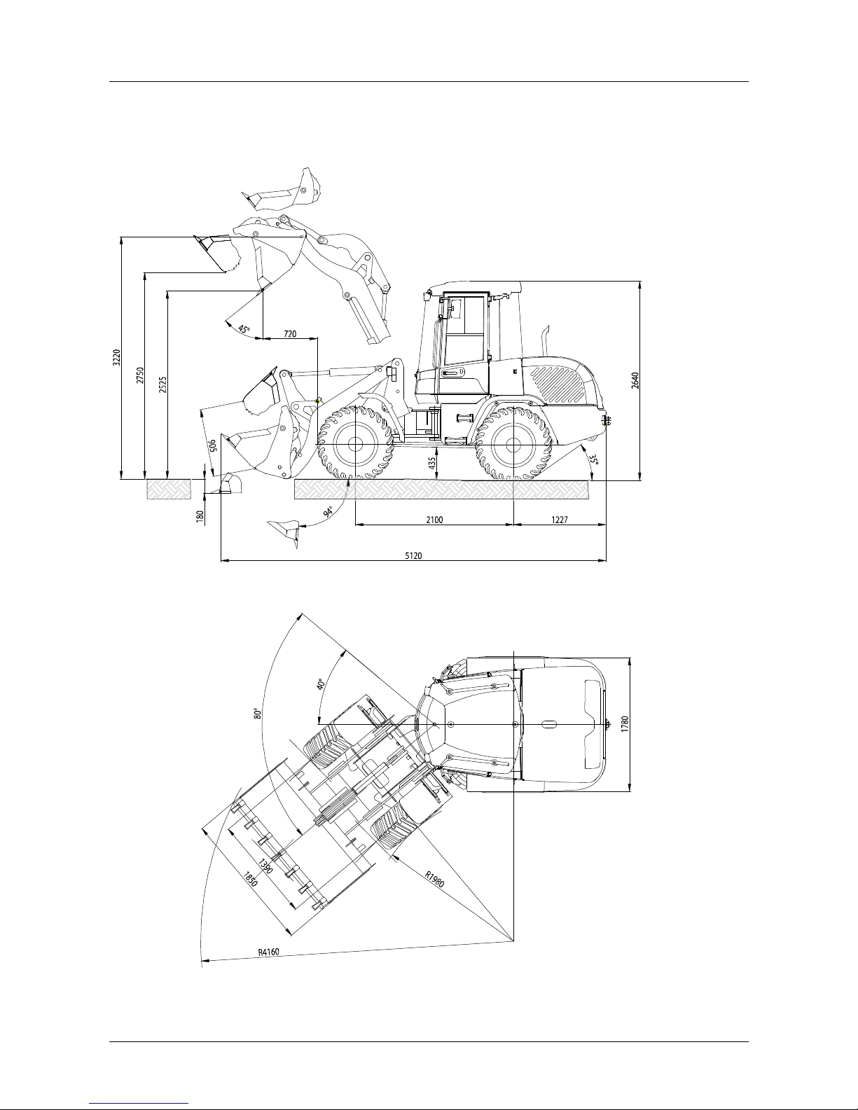
• General-purpose bucket and Z kinematics
Fig. 6 Dimensioned drawing - standard bucket and Z kinematics
Tires 405/70 R18
Technical data 3
TL80 21
• Multi-purpose bucket and Z kinematics
Fig. 7 Dimensioned drawing - multi-purpose bucket and Z kinematics
Tires 405/70 R18
3 Technical data
22 TL80
• Fork lift attachment and Z kinematics
Fig. 8 Dimensioned drawing - fork lift attachment and Z kinematics
Tires 405/70 R18
Technical data 3
TL80 23
• Low profile canopy with general-purpose bucket 0.8 m³
Fig. 9 Dimensioned drawing - low profile canopy with standard bucket 0.8 m³
Tires 15.5/55 R18
3 Technical data
24 TL80
• Fold-down bar with general-purpose bucket 0.8 m³
Fig. 10 Dimensioned drawing - fold-down bar with standard bucket 0.8 m³
Tires 15.5/55 R18
 Loading...