

Terex TL260 Operating Instructions Manual
Wheel Loader
tl260
OPERATING INSTRUCTIONS
Wheel Loader
tl260
Language version: EN
Edition: 2010-03
Order number: 5780200553
From vehicle ID No: TL02600135>
Original operating instructions

®
Terex Compact Germany GmbH
Kraftwerkstraße 4
74564 Crailsheim
Germany
Tel. +49(0)79 51/9 35 70
Fax +49(0)79 51/9 35 76 71
www.terexconstruction.com
e-mail: info@terex-compact.com
Please complete before commissioning the wheel loader:
Vehicle model: .........................................................................................
Vehicle ID-No: .........................................................................................
Year of construction: ........................................................................................
Commissioned on: .........................................................................................
Dealer:
This Operating Manual is protected by limited copyright. It may be reprod uced for and used by the driver
/ plant operator.

Table of Contents
1 Table of Contents
1 Table of Contents . . . . . . . . . . . . . . . . . . . . . . . . . . . . . . . . . . . . . . . . . . 1
2 Introduction . . . . . . . . . . . . . . . . . . . . . . . . . . . . . . . . . . . . . . . . . . . . . . . 5
2.1 Concerning these operating instructions . . . . . . . . . . . . . . . . . 5
2.2 Notes on using the operating manual . . . . . . . . . . . . . . . . . . . . 7
2.3 Intended use. . . . . . . . . . . . . . . . . . . . . . . . . . . . . . . . . . . . . . . . . 8
2.4 Unintended use . . . . . . . . . . . . . . . . . . . . . . . . . . . . . . . . . . . . . . 8
2.5 Warranty. . . . . . . . . . . . . . . . . . . . . . . . . . . . . . . . . . . . . . . . . . . . 8
2.6 Declaration of Conformity. . . . . . . . . . . . . . . . . . . . . . . . . . . . . . 9
3 Safety . . . . . . . . . . . . . . . . . . . . . . . . . . . . . . . . . . . . . . . . . . . . . . . . . . . 11
3.1 General safety notes . . . . . . . . . . . . . . . . . . . . . . . . . . . . . . . . . 11
3.1.1 Safety symbol . . . . . . . . . . . . . . . . . . . . . . . . . . . . . . . . . . . . . . . 11
3.1.2 Hazard Classification. . . . . . . . . . . . . . . . . . . . . . . . . . . . . . . . . . 11
3.1.3 Descriptions of symbols and hazard pictorials. . . . . . . . . . . . . . . 13
1
3.2 Location of safety signs . . . . . . . . . . . . . . . . . . . . . . . . . . . . . . 14
3.2.1 Pictograms. . . . . . . . . . . . . . . . . . . . . . . . . . . . . . . . . . . . . . . . . . 15
3.3 Personal safety . . . . . . . . . . . . . . . . . . . . . . . . . . . . . . . . . . . . . 18
3.3.1 Personal safety gear . . . . . . . . . . . . . . . . . . . . . . . . . . . . . . . . . . 18
3.4 Work zone safety. . . . . . . . . . . . . . . . . . . . . . . . . . . . . . . . . . . . 19
3.4.1 General work zone regulations and safe work practices. . . . . . . 19
3.4.2 Deactivation and protection against re-activation . . . . . . . . . . . . 19
3.5 General safety notes . . . . . . . . . . . . . . . . . . . . . . . . . . . . . . . . . 20
3.6 Operation . . . . . . . . . . . . . . . . . . . . . . . . . . . . . . . . . . . . . . . . . . 21
3.7 Danger zone. . . . . . . . . . . . . . . . . . . . . . . . . . . . . . . . . . . . . . . . 22
3.8 Transporting persons . . . . . . . . . . . . . . . . . . . . . . . . . . . . . . . . 22
3.9 Stability. . . . . . . . . . . . . . . . . . . . . . . . . . . . . . . . . . . . . . . . . . . . 22
3.9.1 Stability on sloping ground. . . . . . . . . . . . . . . . . . . . . . . . . . . . . . 22
3.10 Driving . . . . . . . . . . . . . . . . . . . . . . . . . . . . . . . . . . . . . . . . . . . . 24
3.11 Working Operation . . . . . . . . . . . . . . . . . . . . . . . . . . . . . . . . . . 24
3.12 Guides. . . . . . . . . . . . . . . . . . . . . . . . . . . . . . . . . . . . . . . . . . . . . 25
3.13 Use under the danger of falling objects . . . . . . . . . . . . . . . . . 25
3.14 Working in the vicinity of underground power lines . . . . . . . 25
3.15 Working in the vicinity of overhead power lines . . . . . . . . . . 26
3.16 Operation in closed spaces . . . . . . . . . . . . . . . . . . . . . . . . . . . 27
01_Table of Contents_enIV Z.fm - V 0.1 - 14.4.11
TL260
1 / 187
4

1
Table of Contents
3.17 Work stoppages . . . . . . . . . . . . . . . . . . . . . . . . . . . . . . . . . . . . .27
3.18 Load hook applications . . . . . . . . . . . . . . . . . . . . . . . . . . . . . . .28
3.19 Conversions, maintenance and repairs . . . . . . . . . . . . . . . . . .29
3.20 Recovery, loading and transporting . . . . . . . . . . . . . . . . . . . . .31
3.21 Monitoring and inspections. . . . . . . . . . . . . . . . . . . . . . . . . . . .31
3.22 Fire prevention . . . . . . . . . . . . . . . . . . . . . . . . . . . . . . . . . . . . . .32
3.23 Emergency exit . . . . . . . . . . . . . . . . . . . . . . . . . . . . . . . . . . . . . .32
3.24 Notes concerning residual dangers . . . . . . . . . . . . . . . . . . . . .32
3.24.1 Failure of hydraulic system. . . . . . . . . . . . . . . . . . . . . . . . . . . . . .32
4 Initial installation and adjustments. . . . . . . . . . . . . . . . . . . . . . . . . . . .33
4.1 Initial familiarization . . . . . . . . . . . . . . . . . . . . . . . . . . . . . . . . . .33
4.1.1 Handing over the machine and instructing the operator. . . . . . . .33
5 Description of the Wheel Loader. . . . . . . . . . . . . . . . . . . . . . . . . . . . . .35
5.1 Overview of wheel loader. . . . . . . . . . . . . . . . . . . . . . . . . . . . . .35
5.1.1 Overview filters . . . . . . . . . . . . . . . . . . . . . . . . . . . . . . . . . . . . . . .36
5.2 Display elements and operating controls in operator's stand37
5.2.1 Operating controls. . . . . . . . . . . . . . . . . . . . . . . . . . . . . . . . . . . . .37
5.2.2 Front control console . . . . . . . . . . . . . . . . . . . . . . . . . . . . . . . . . .38
5.2.3 Lateral control console . . . . . . . . . . . . . . . . . . . . . . . . . . . . . . . . .39
5.2.4 Control unit heating / Klimatronic . . . . . . . . . . . . . . . . . . . . . . . . .40
5.2.5 Display . . . . . . . . . . . . . . . . . . . . . . . . . . . . . . . . . . . . . . . . . . . . .41
5.2.6 Fuse and relay box . . . . . . . . . . . . . . . . . . . . . . . . . . . . . . . . . . . .42
5.2.7 Driver's seat . . . . . . . . . . . . . . . . . . . . . . . . . . . . . . . . . . . . . . . . .45
5.3 Type label . . . . . . . . . . . . . . . . . . . . . . . . . . . . . . . . . . . . . . . . . .46
6 Maintenance . . . . . . . . . . . . . . . . . . . . . . . . . . . . . . . . . . . . . . . . . . . . . .47
6.1 General. . . . . . . . . . . . . . . . . . . . . . . . . . . . . . . . . . . . . . . . . . . . .47
6.2 Care and cleaning. . . . . . . . . . . . . . . . . . . . . . . . . . . . . . . . . . . .47
6.3 Inspection intervals . . . . . . . . . . . . . . . . . . . . . . . . . . . . . . . . . .48
6.3.1 Regular oil analysis. . . . . . . . . . . . . . . . . . . . . . . . . . . . . . . . . . . .49
6.3.2 Warranty . . . . . . . . . . . . . . . . . . . . . . . . . . . . . . . . . . . . . . . . . . . .50
6.4 Inspection means . . . . . . . . . . . . . . . . . . . . . . . . . . . . . . . . . . . .51
6.4.1 Service parts. . . . . . . . . . . . . . . . . . . . . . . . . . . . . . . . . . . . . . . . .51
6.4.2 Consumables . . . . . . . . . . . . . . . . . . . . . . . . . . . . . . . . . . . . . . . .52
6.5 Lubrication . . . . . . . . . . . . . . . . . . . . . . . . . . . . . . . . . . . . . . . . .57
6.5.1 Lubrication plan. . . . . . . . . . . . . . . . . . . . . . . . . . . . . . . . . . . . . . .58
6.6 Maintenance and Inspection Plan. . . . . . . . . . . . . . . . . . . . . . .60
6.6.1 Daily tasks. . . . . . . . . . . . . . . . . . . . . . . . . . . . . . . . . . . . . . . . . . .60
6.6.2 Tasks to be performed weekly . . . . . . . . . . . . . . . . . . . . . . . . . . .61
2 / 187
4
TL260
01_Table of Contents_enIVZ.fm - V 0.1 - 14.4.11

Table of Contents
6.6.3 Inspection plan machine . . . . . . . . . . . . . . . . . . . . . . . . . . . . . . . 62
6.7 Maintenance and inspection work. . . . . . . . . . . . . . . . . . . . . . 65
6.7.1 Display. . . . . . . . . . . . . . . . . . . . . . . . . . . . . . . . . . . . . . . . . . . . . 66
6.7.2 Engine . . . . . . . . . . . . . . . . . . . . . . . . . . . . . . . . . . . . . . . . . . . . . 67
6.7.3 Engine - cooling system. . . . . . . . . . . . . . . . . . . . . . . . . . . . . . . . 70
6.7.4 Air intake system . . . . . . . . . . . . . . . . . . . . . . . . . . . . . . . . . . . . . 76
6.7.5 Fuel system . . . . . . . . . . . . . . . . . . . . . . . . . . . . . . . . . . . . . . . . . 81
6.7.6 V-belt . . . . . . . . . . . . . . . . . . . . . . . . . . . . . . . . . . . . . . . . . . . . . . 85
6.7.7 Hydraulic oil tank . . . . . . . . . . . . . . . . . . . . . . . . . . . . . . . . . . . . . 87
6.7.8 Hydraulic oil suction filter. . . . . . . . . . . . . . . . . . . . . . . . . . . . . . . 91
6.7.9 Hydraulic oil return filter. . . . . . . . . . . . . . . . . . . . . . . . . . . . . . . . 93
6.7.10 Axles . . . . . . . . . . . . . . . . . . . . . . . . . . . . . . . . . . . . . . . . . . . . . . 95
6.7.11 Wheels. . . . . . . . . . . . . . . . . . . . . . . . . . . . . . . . . . . . . . . . . . . . 101
6.7.12 Electrical equipment . . . . . . . . . . . . . . . . . . . . . . . . . . . . . . . . . 102
6.7.13 Cab ventilation dust filter . . . . . . . . . . . . . . . . . . . . . . . . . . . . . . 105
6.7.14 Windshield washer system . . . . . . . . . . . . . . . . . . . . . . . . . . . . 107
1
6.8 Taking out of service. . . . . . . . . . . . . . . . . . . . . . . . . . . . . . . . 108
6.8.1 Preservation (temporary immobilization ) . . . . . . . . . . . . . . . . . 108
6.8.2 While being taken out of service . . . . . . . . . . . . . . . . . . . . . . . . 109
6.8.3 After the machine had been taken out of service . . . . . . . . . . . 109
6.8.4 Disposal. . . . . . . . . . . . . . . . . . . . . . . . . . . . . . . . . . . . . . . . . . . 109
7 Operation . . . . . . . . . . . . . . . . . . . . . . . . . . . . . . . . . . . . . . . . . . . . . . . 111
7.1 Before operation . . . . . . . . . . . . . . . . . . . . . . . . . . . . . . . . . . . 111
7.1.1 Adjustments. . . . . . . . . . . . . . . . . . . . . . . . . . . . . . . . . . . . . . . . 112
7.2 Operation . . . . . . . . . . . . . . . . . . . . . . . . . . . . . . . . . . . . . . . . . 117
7.2.1 Monitoring the machine during operation . . . . . . . . . . . . . . . . . 124
7.2.2 Driving, steering and braking. . . . . . . . . . . . . . . . . . . . . . . . . . . 125
7.2.3 Working operation . . . . . . . . . . . . . . . . . . . . . . . . . . . . . . . . . . . 136
7.2.4 Changing work attachments . . . . . . . . . . . . . . . . . . . . . . . . . . . 141
7.2.5 Loading, grading, excavating. . . . . . . . . . . . . . . . . . . . . . . . . . . 144
7.2.6 Ride control system (RCS) (option). . . . . . . . . . . . . . . . . . . . . . 146
7.2.7 Hydroinflation of tires. . . . . . . . . . . . . . . . . . . . . . . . . . . . . . . . . 148
7.2.8 Notes for winter operation . . . . . . . . . . . . . . . . . . . . . . . . . . . . . 149
8 Transportation . . . . . . . . . . . . . . . . . . . . . . . . . . . . . . . . . . . . . . . . . . . 151
8.1 Recovering the wheel loader . . . . . . . . . . . . . . . . . . . . . . . . . 151
8.2 Lifting with a crane . . . . . . . . . . . . . . . . . . . . . . . . . . . . . . . . . 155
8.3 Transport . . . . . . . . . . . . . . . . . . . . . . . . . . . . . . . . . . . . . . . . . 156
9 Specifications . . . . . . . . . . . . . . . . . . . . . . . . . . . . . . . . . . . . . . . . . . . 157
01_Table of Contents_enIV Z.fm - V 0.1 - 14.4.11
TL260
3 / 187
4

1
Table of Contents
9.1 Views . . . . . . . . . . . . . . . . . . . . . . . . . . . . . . . . . . . . . . . . . . . . .157
9.1.1 Dimensioned drawing with bucket, directly mounted . . . . . . . . .157
9.1.2 Dimensioned drawing with bucket and quick-attach system. . . .158
9.1.3 Dimensioned drawing with light-material bucket and quick-attach system159
9.2 Technical data. . . . . . . . . . . . . . . . . . . . . . . . . . . . . . . . . . . . . .160
9.2.1 Engine. . . . . . . . . . . . . . . . . . . . . . . . . . . . . . . . . . . . . . . . . . . . .160
9.2.2 Electrical system. . . . . . . . . . . . . . . . . . . . . . . . . . . . . . . . . . . . .160
9.2.3 Travel drive. . . . . . . . . . . . . . . . . . . . . . . . . . . . . . . . . . . . . . . . .161
9.2.4 Brakes. . . . . . . . . . . . . . . . . . . . . . . . . . . . . . . . . . . . . . . . . . . . .161
9.2.5 Hydraulics. . . . . . . . . . . . . . . . . . . . . . . . . . . . . . . . . . . . . . . . . .162
9.2.6 Permissible loads in compliance with German Road Traffic Regulations (StVZO)163
9.2.7 Sound level values, vibration, vibration values. . . . . . . . . . . . . .163
9.3 Dimensions and weights . . . . . . . . . . . . . . . . . . . . . . . . . . . . .164
9.3.1 Cab . . . . . . . . . . . . . . . . . . . . . . . . . . . . . . . . . . . . . . . . . . . . . . .167
9.3.2 Pressure chart. . . . . . . . . . . . . . . . . . . . . . . . . . . . . . . . . . . . . . .168
9.3.3 Optional accessories. . . . . . . . . . . . . . . . . . . . . . . . . . . . . . . . . .169
10 Troubleshooting . . . . . . . . . . . . . . . . . . . . . . . . . . . . . . . . . . . . . . . . . .171
10.1 Who is allowed to rectify malfunctions? . . . . . . . . . . . . . . . .171
10.2 Before trouble shooting and fault rectification . . . . . . . . . . .171
10.3 Trouble shooting and fault rectification. . . . . . . . . . . . . . . . .172
10.3.1 Immobilizer faults . . . . . . . . . . . . . . . . . . . . . . . . . . . . . . . . . . . .178
11 Service and spare parts information. . . . . . . . . . . . . . . . . . . . . . . . . .179
11.1 Spare parts . . . . . . . . . . . . . . . . . . . . . . . . . . . . . . . . . . . . . . . .179
11.2 Service. . . . . . . . . . . . . . . . . . . . . . . . . . . . . . . . . . . . . . . . . . . .179
12 Index. . . . . . . . . . . . . . . . . . . . . . . . . . . . . . . . . . . . . . . . . . . . . . . . . . . .181
4 / 187
4
TL260
01_Table of Contents_enIVZ.fm - V 0.1 - 14.4.11

2 Introduction
2.1 Concerning these operating instructions
Introduction
2
Economical
operation
Reading the
operating
instructions
Deployment
location
Technical
modifications
Copyright This operating manual is copyrighted. It must not be copied, disseminated or
The operating manual contains important information regarding the safe, correct
and economical operation of the wheel loader. Strict compliance with these
instructions helps to avoid dangers, to reduce repair costs and downtimes and
to enhance the reliability and service life of the wheel loader.
Read these operating instructions thoroughly to become acquainted with correct
handling and operation.
These operating instructions must always be available at the deployment
location of the wheel loader.
Items described in this manual are subject of changes without prior notification.
used for competitive purposes, either fully or in part, without prior written
permission.
02_Introduction_en.fm - V 0.1 - 14.4.11
TL260
5 / 187
10

2
Introduction
Definition of
target groups
The contents of these operating instructions are aimed at a diverse target
audience. The level of knowledge each target group must have is defined here.
All target groups must have read these operating instructions and understood
their contents.
Operating personnel must
• be physically and mentally fit and suitable.
• be of the legal minimum age.
• have been instructed in handling the wheel loader.
• have proven their ability to operate the wheel loader to the operating
company.
• have been appointed by the operating company to operate the whe el loader.
• be familiar with the country-specific accident-prevention regulations.
Maintenance personnel must
• be physically and mentally fit and suitable.
• be of the legal minimum age.
• know the maintenance points on the wheel loader.
• have proven their ability to perform maintenance work on the wheel loader to
the operating company.
• have been appointed by the operating company to perform maintenance
work on the wheel loader.
• know the country-specific environmental regulations for the disposal of
lubricants. See chapter "Regulations concerning environmental protection",
page 21.
Service personnel must
• be physically and mentally fit and suitable.
• be of the legal minimum age.
• have sound school education and vocational training.
• have been trained by Terex for service work on the wheel loader.
• must have been trained in the rules and procedures related to a case of
malfunction.
6 / 187
10
TL260
02_Introduction_en.fm - V 0.1 - 14.4.11
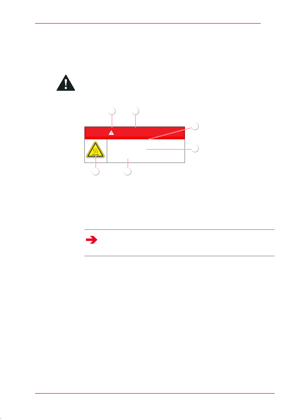
Safety symbol
GEFAHR
DANGER
Type of danger
Consequence of danger
Z Action against danger
3
6
1 2
5
4
Structure of
safety notes
Introduction
2.2 Notes on using the operating manual
The safety symbol is used to warn you of potential personal injury. Obey all
safety messages that follow this symbol to avoid possible injury or death.
2
Notes
Fig. 2-1 Structure of safety notes
1 Safety symbol
2 Signal word for danger level
3 Type and source of hazard
4 Possible consequence of danger
5 Measures for hazard prevention
6 Safety symbol
Note
This symbol is employed for information containing important notes about
the correct use and/or how to proceed. Non-compliance may lead to
malfunction.
02_Introduction_en.fm - V 0.1 - 14.4.11
TL260
7 / 187
10

2
Introduction
2.3 Intended use
The Terex wheel loader TL260 with standard equipment is solely intended for
the following type of work:
• Loosening, picking up, transporting and dumping soil, rock or other materials
• Loading these materials on trucks, conveyor belts or other means of
transport, when the transport of the material is normally done by positioning
the earth-moving machine
After installation of additionally approved special work attachments, such as
e. g. :
• Multi-purpose bucket
• High-tip bucket
• Fork lift attachment
•etc.
the equipment can be used for corresponding applications.
Strict compliance with the operating and maintenance instructions and the
performance of maintenance work, as well as adherence to the maintenance
intervals is also part of intended use. The operator must also follow th e enclosed
operating instructions for externally supplied components.
2.4 Unintended use
Using the Terex wheel loader TL260 for following types of work is considered
unintended:
• transport of persons
• transport of material on public roads
• used as man-platform
The supplier cannot be held responsible for any damage resulting from improper
use. This risk is borne solely by the user.
2.5 Warranty
The warranty period covers 12 months, beginning with the day the machine is
handed over or put into operation.
8 / 187
10
TL260
02_Introduction_en.fm - V 0.1 - 14.4.11
Introduction
2
2.6 Declaration of Conformity
The wheel loader meets the general requirements of the applicable European
directives.
Conformity has been proven. The respective documents and the original of the
Certificate of Conformity are kept by the manufacturer.
A copy of the Certificate of Conformity is attached to the sales documents.
EC declaration of conformity
according to the Machinery Directive 2006/42/EC
1. We hereby declare that the earth-moving machine of type TL 260:
2. complies with the following applicable regulations:
3. Representative sound power level:
4. Guaranteed sound power level:
5. Applied harmonized standards:
6. Applied European standards:
7. Document editor, who is authorized to compile technical documentation:
8. Voluntary type examination performed as well as certification in accordance with
The EC declaration of conformity only applies if the earth-moving machine is used in accordance
with the operating instructions. It includes the use of original Terex work attachments and other
work attachments, which are mentioned in the operating instructions or in other Terex
documentation for application on this earth-moving machine.
Replaceable attachments manufactured by Terex or third party manufacturers may only be
installed and used if the installation on the affected earth-moving machine is performed by Terex.
In all other cases, special written approval is required from Terex.
Date of the declaration of conformity 29.12.2009
Langenburg
Wheel loader: TL 260
Vehicle ID No.: TL0260
Actual productivity: 129 kW
2006/42/EC, 2004/108/EC (EMC), RL 2000/14/EC Appendix VIII (noise emission)
103.4 dB(A)
105 dB(A)
EN ISO 12100-2
EN 474-1
EN 474-3
Maik Schulze, D 74564 Crailsheim, Kraftwerkstrasse 4
RL 2000/14/EC Appendix VIII at:
Fachausschüsse Bau (BAU) und Tiefbau (TB)
Prüf- und Zertifizierungsstelle im BG-PRÜFZERT
80687 Munich, Germany
02_Introduction_en.fm - V 0.1 - 14.4.11
Terex GmbH
Geschäftsbereich Terex Schaeff
Schaeffstrasse 8
74595 Langenburg, Germany
TL260
9 / 187
10

2
Introduction
10 / 187
10
TL260
02_Introduction_en.fm - V 0.1 - 14.4.11
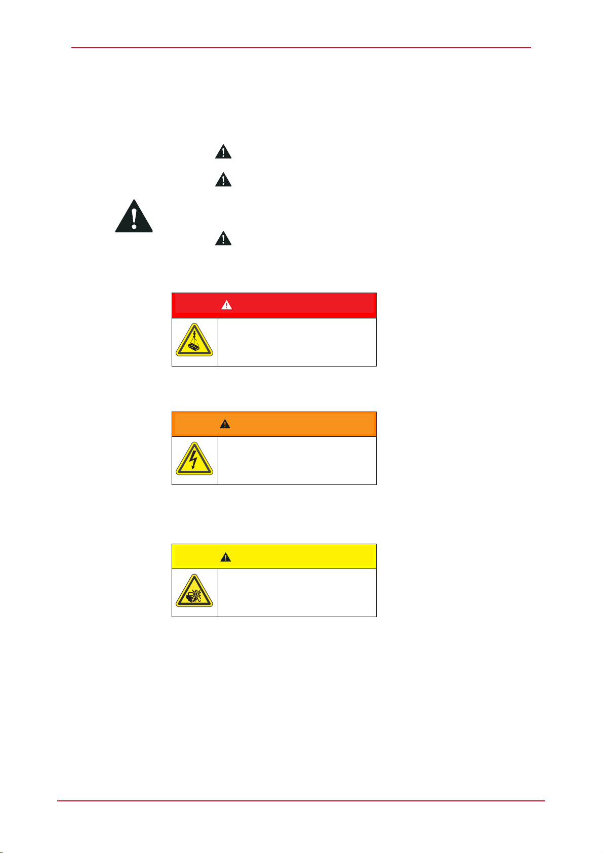
Safety
GEFAHR
DANGER
WARNUNG
WARNING
VORSICHT
CAUTION
3
3 Safety
3.1 General safety notes
3.1.1 Safety symbol
The safety symbol is used to warn you of potential personal injury. Obey all
safety messages that follow this symbol to avoid possible injury or death.
3.1.2 Hazard Classification
Danger Indicates an imminently hazardous situation which, if the safety regulations are
not observed, will result in death or serious injury.
Warning Indicates a potentially hazardous situation which, if the safety regulations are
not observed, may result in death or serious injury.
Caution Indicates a potentially hazardous situation which, if the safety regulations are
not observed, may result in property or equipment damage, or minor or
moderate personal injury.
03_Safety_en.fm - V 0.1 - 14.4.11
TL260
11 / 187
32

3
CAUTION
Safety
Caution without safety
symbol
Indicates a potentially hazardous situation which, if the safety regulations are
not observed, may result in property or equipment damage.
12 / 187
32
TL260
03_Safety_en.fm - V 0.1 - 14.4.11
Safety
3
3.1.3 Descriptions of symbols and hazard pictorials
The symbols used in this Manual and on the machine identify the following
hazards:
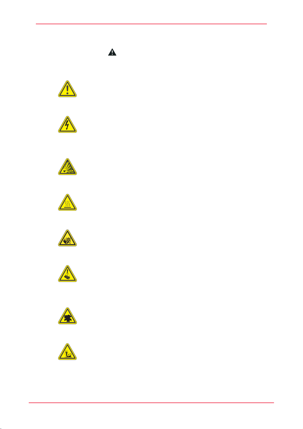
Warning of a hazardous spot
If the required precautionary measures are not taken, death, personal injury,
and substantial property or equipment damage may occur.
Warning of hazardous electric voltage
If the required precautionary measures are not taken, high electric voltage, high
load currents (on terminals, capacitors, housing parts and printed circuit boards)
may lead to death, physical injury or considerable property damage.
Warning of explosion danger
If the required precautionary measures are not taken, death, burns or blindness
due to explosive gases or contact with corrosive acids can occur.
Warning against danger of burning
If the required precautionary measures are not taken, personal injury caused by
burning may occur.
Warning of crushing danger
If the required precautionary measures are not taken, personal injury due to
crushing may occur.
Warning of suspended load
If the required precautionary measures are not taken, death, personal injury,
and substantial property or equipment damage may occur due to suspended or
falling loads.
Warning of hazardous dusts
If the required precautionary measures are not taken, personal injury caused by
inhaling hazardous dusts may occur.
03_Safety_en.fm - V 0.1 - 14.4.11
Warning of environmentally hazardous substances
If the required precautionary measures are not taken, these substances may
cause serious environmental damage.
TL260
13 / 187
32
3
Safety
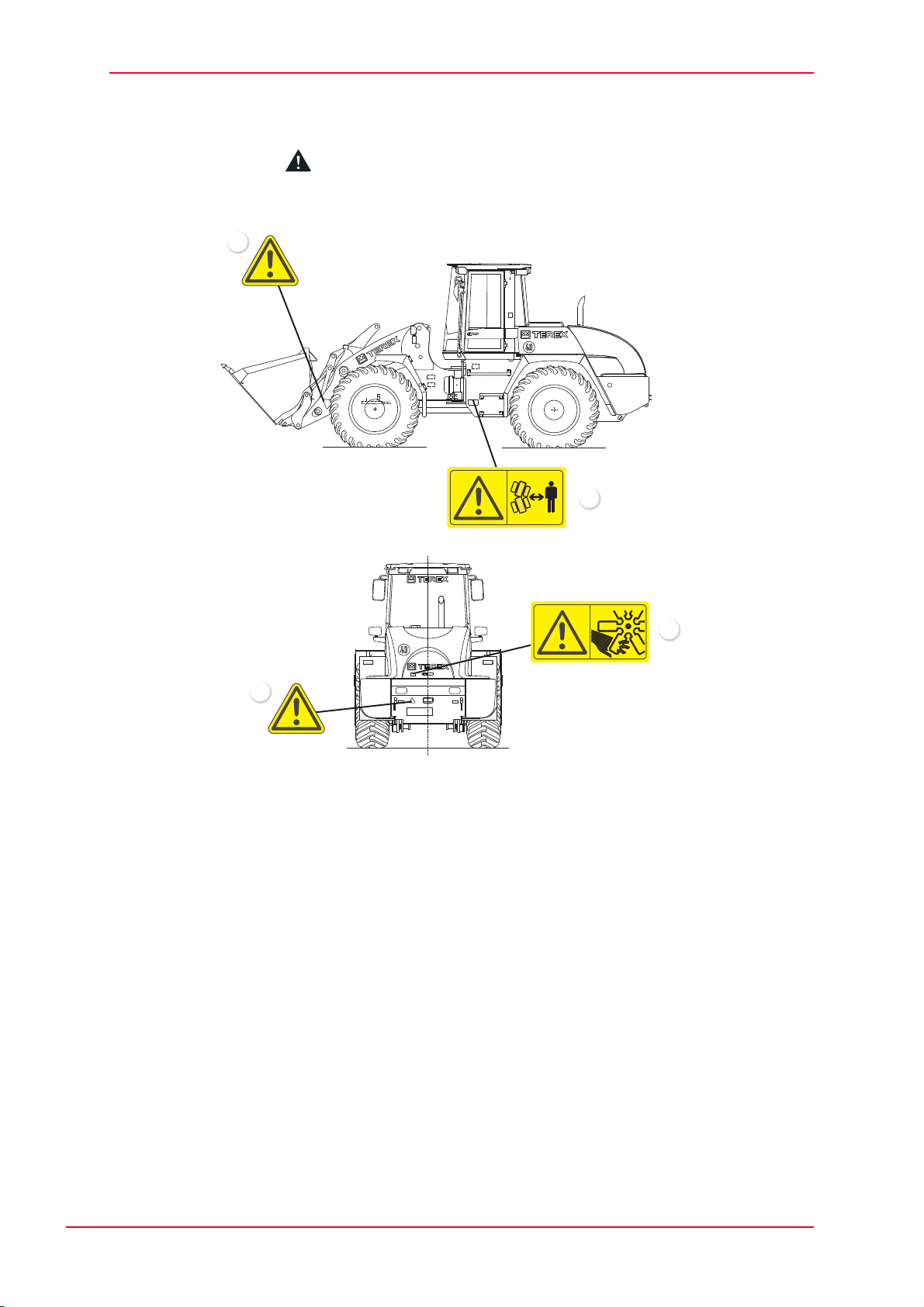
3.2 Location of safety signs
The safety signs are located in the following machine positions:
1
4
2
Fig. 3-1 Locations of safety signs
1 Safety distance (left and right sides of lifting frame)
2 Safety distance
3 Danger of injury
4 Danger of crushing
3
4560_3001
14 / 187
32
TL260
03_Safety_en.fm - V 0.1 - 14.4.11
Safety
P
VRV
R
Servicing and replacing safety signs
The safety of the operator always has to come first.
Safety signs must always be kept in good condition and legible.
Replace any safety sign which has been damaged or disappeared.
Use mild detergents and water to clean the safety signs.
Do not use any solvent containing cleansers.
Always specify machine serial number and language when ordering safety
signs.
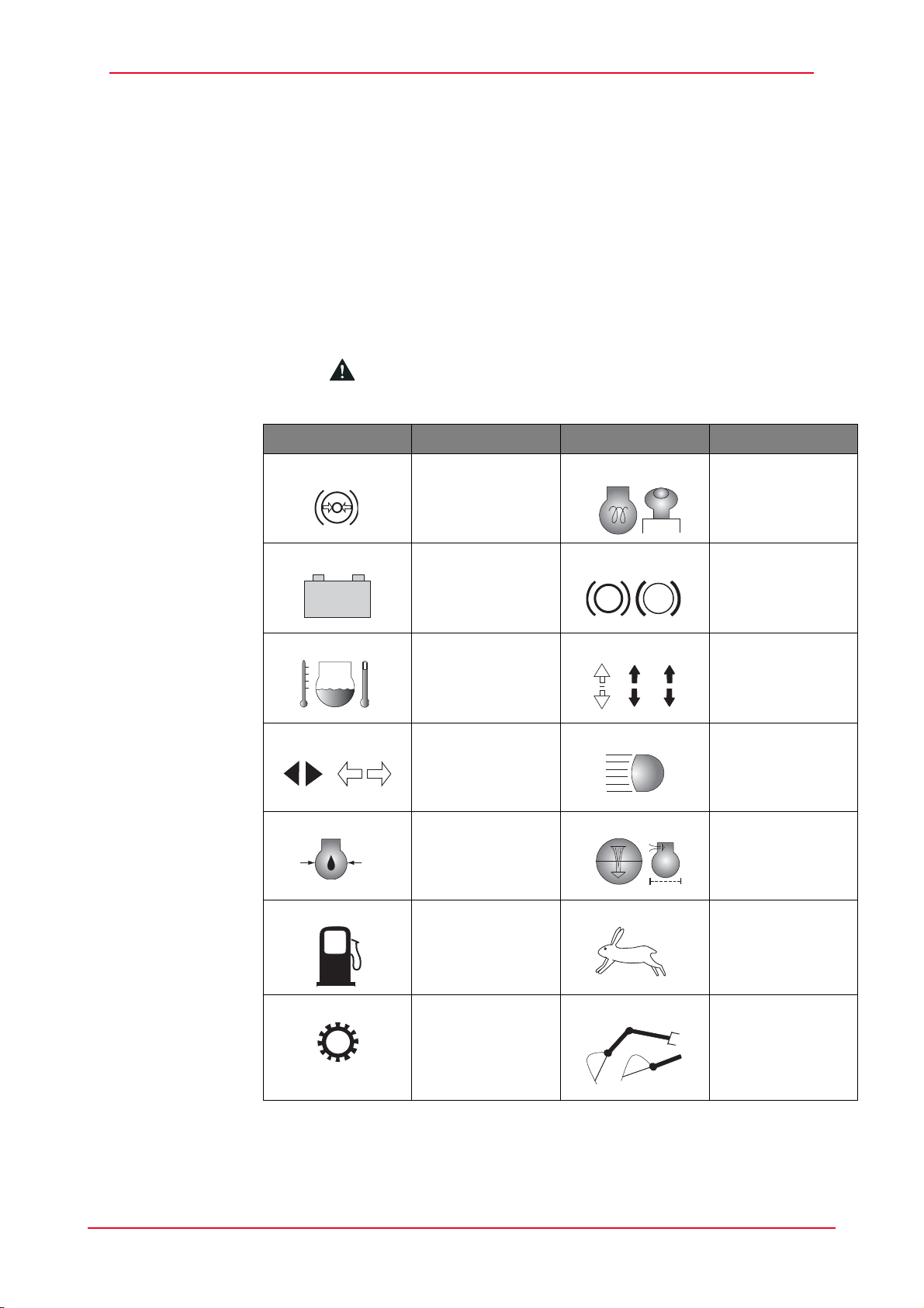
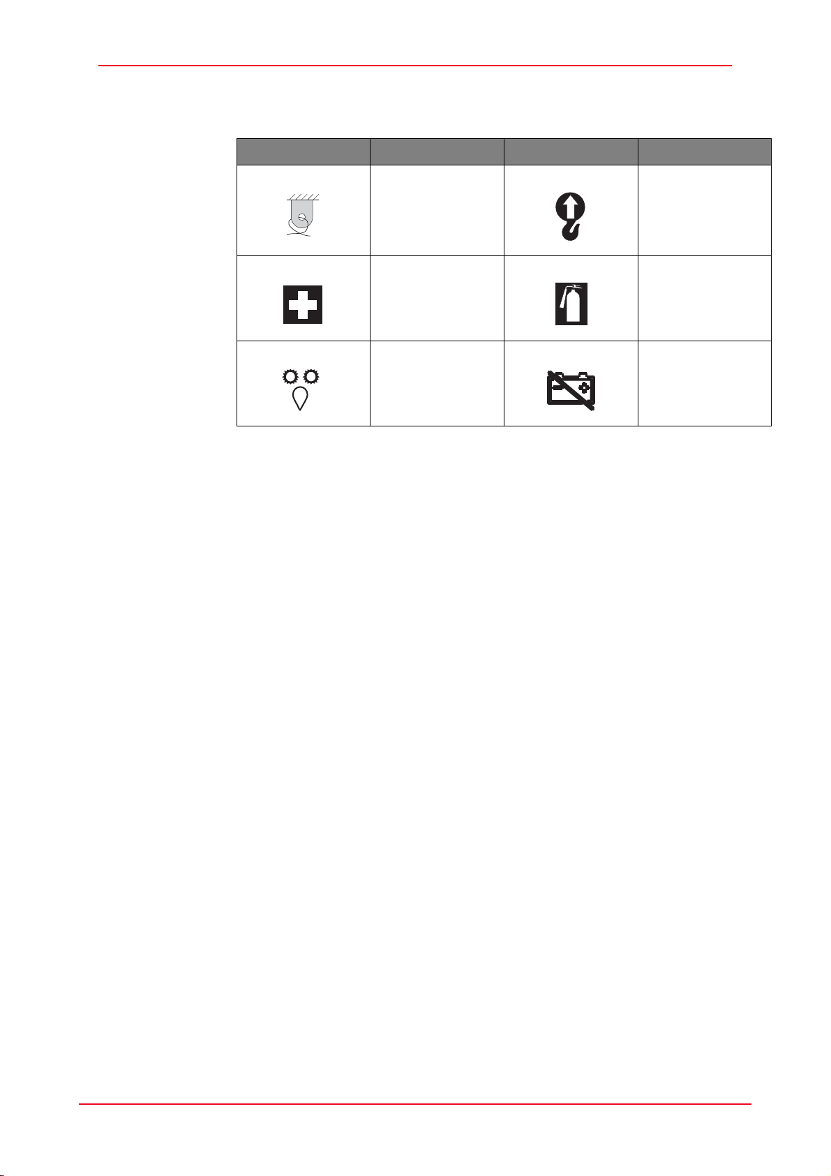
3.2.1 Pictograms
The following pictograms may be attached to the machine:
Pictograms Description Pictograms Description
3
- +
Brake
Preheating
accumulator
pressure
Battery charge
Parking brake
indicator
P
Coolant
temperature
Direction
indicator LT/RT
Engine oil
Travel direction
FWD/REV
High-beam
indicator
Air filter
pressure
Fuel Travel speed,
FAST
High gear Working
hydraulics shut-
II
03_Safety_en.fm - V 0.1 - 14.4.11
TL260
off
15 / 187
32
3
Safety
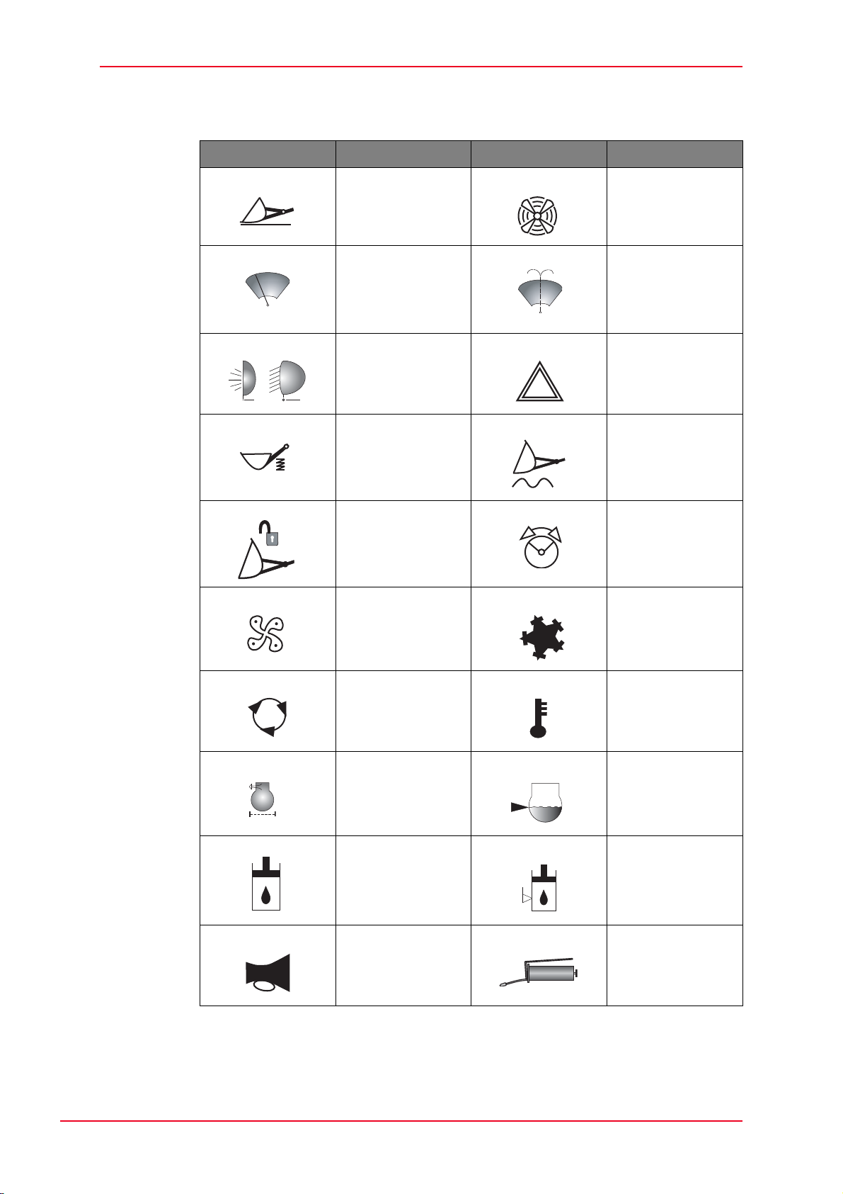
Pictograms Description Pictograms Description
Bucket return
positioner
Windshield wiper Windshield
Working
floodlights
Ride control
system
Unlocked Emergency
Changeover fan/
engine cooling
washing function
Hazard warning
system
Float position
steering
Fan levels Cooling
Circulating air Temperature
Carbon filter
contamination
Hydraulic oil Hydraulic oil
Horn Grease gun
Coolant level
level
16 / 187
32
TL260
03_Safety_en.fm - V 0.1 - 14.4.11
Safety
Pictograms Description Pictograms Description
Lashing points Suspension
points for loading
by crane
First-aid kit Fire extinguisher
3
Intermediate
lubrication
Battery cutoff
03_Safety_en.fm - V 0.1 - 14.4.11
TL260
17 / 187
32

3
Safety
3.3 Personal safety
The Operating Instructions and the symbols described have to be read and
understood by all persons working on and with the machine.
3.3.1 Personal safety gear
The mandatory signs used in this Manual and on the machine require the
following safety measures:
Working with protective clothing
If the required protective clothing is not worn during work, personal injury may
result.
Working with protective gloves
If the required protective gloves are not worn during work, hand injuries may
result.
Working with protective goggles
If the required protective goggles are not worn during work, eye injuries or a total
loss of sight may result.
Working with hearing protection
If the required hearing protection is not worn during work, hearing defects may
result.
Working with respiratory protection
If the required respiratory protection is not worn during work, health effects may
result.
Working with protective face shield
If the required protective face shield is not worn during work, facial injuries may
result.
18 / 187
32
TL260
03_Safety_en.fm - V 0.1 - 14.4.11

Safety
3
3.4 Work zone safety
3.4.1 General work zone regulations and safe work practices
Read the operating instructions thoroughly and follow the notes on safe
operation before putting the machine into operation.
In addition to the operating instructions observe also the national legal and
miscellaneous regulations applicable at the deployment location of the machine:
• Industrial safety
• Accident prevention
• Health protection
• Environmental protection
• Public traffic
Such duties could also apply in respect of e. g. handling hazardous goods or the
wearing of personal safety gear.
Furthermore, safety laws governing work in particular locations (tunnels, adits,
quarries, pontoons, contaminated areas, etc.) must likewise be observed, e. g.:
• Working in the vicinity of tracks (BGV D33)
• Construction work (BGV C22)
• Safety rules for construction work underground (BGR 160)
• Tunnel excavating machines (DIN EN 12111)
The plant operator and the machine driver are responsible for ensuring that the
safety regulations are upheld. The customer must in any case become familiar
with the locally valid rules and regulations.
3.4.2 Deactivation and protection against re-activation
Ensure all the following safety instructions are read prior to using or servicing
the machine, to avoid personal injury.
Before breaks and the end of work park the machine on a solid and level
base.
The machine is only to be parked in places where it does not obstruct e. g.
the public or the construction site traffic.
Place the working attachment on the floor.
Shut down the engine and pull out the ignition key.
Close or lock windows and doors.
03_Safety_en.fm - V 0.1 - 14.4.11
TL260
19 / 187
32

3
Safety
3.5 General safety notes
• It is important to refrain from any working methods which impair safety.
• The machine may only be operated with cabin or canopy.
• The machine is only to be used if it is in a safe, operational condition.
• The manufacturer’s instructions must be complied with for operation,
maintenance, repair, assembly, and transportation.
• The plant operator must provide additional special safety instructions,
wherever necessary, for specific local conditions.
• The operating instructions and any information pertaining to safety must be
carefully kept in the driver's cab.
• The operating instructions and safety notes must be complete and fully
readable.
Before starting
work:
During work
Before starting work become acquainted with the First Aid and Rescue
Possibilities (Emergency Doctor, Fire Brigade, Rescue Services).
Check that the first aid kit is available and properly stocked.
Become familiar with the location and the operation of fire extinguishers on
the machine, as well as the local fire alarm and fire fighting facilities.
Fasten any loose parts, e. g. tools and other accessories.
Close all doors, windows, hoods, flaps, or secure these in open condition
against unintended closing.
Do not make any safety features ineffective and do not remove any safety
features.
Wear protective clothing for operation. Take off rings, scarves, open jackets.
Protective goggles, protective boots, helmets, gloves, reflecting jackets, earmuffs, etc. may be required for certain work.
20 / 187
32
TL260
03_Safety_en.fm - V 0.1 - 14.4.11

Safety
3
Regulations
concerning
environmental
protection
Comply with the valid environmental regulations when working on or with the
machine.
Take special care that no environmentally harmful substances, like
lubrication grease and oils, hydraulic oils, fuels, coolants and solvent
containing cleaning fluids do not seep into the ground or the sewer when
performing installation, repair and maintenance work. These substances
must be collected, transported, kept and disposed of in suitable containers.
If the substances listed above enter into the soil, the leak or outlet must be
stopped immediately and the fluid must be cleaned up with a suitable
absorbent material. If necessary, the soil involved must be removed.
Properly dispose of binding agent and excavated material, comply with valid
environmental regulations.
3.6 Operation
Operate the control equipment only from the driver's seat.
To access and exit the machine use only the steps and areas provided for
this purpose.
Make sure that the operator’s stand, access steps and other surfaces on the
machine, which have to be stepped on, are kept free of dirt, grease, oil, ice,
and snow.
03_Safety_en.fm - V 0.1 - 14.4.11
TL260
21 / 187
32

3
Safety
3.7 Danger zone
Nobody is allowed to remain in the machine’s danger zone.
The danger zone encompasses the area around the machine in which persons
may be injured by movements of the machine during operation, its work
implements and attachments, or by swinging out or falling loads.
The machine operator is only to work the machine if nobody is in the danger
zone.
The machine operator must give a warning signal to persons who may be in
danger.
Stop work with the machine, if persons remain in the danger zone despite the
warning.
To ensure no danger of crushing, a sufficient safety distance (min. 0.5 m)
must be kept from solid objects, e. g. buildings, excavation slopes,
scaffolding, other crawler excavators, etc.
If the safety distance cannot be kept, fence off the area between solid
construction elements and the working range of the machine.
If conditions are such that the machine operator’s view of the driving and
working zone is restricted, he must be guided or the driving and working zone
must be secured by means of a solid barricade.
3.8 Transporting persons
The machine must not be used to transport persons.
3.9 Stability
The machine must be used, driven and operated in such a manner that its
stability against overturning is ensured at all times.
Match the travel speed to the local conditions.
Do not exceed the permissible load for the machine.
Keep the machine away from the edges of quarries, pits, mounds and slopes,
to ensure there is no risk of falling. If this is not possible, the machine must
be secured to prevent rolling or slipping.
3.9.1 Stability on sloping ground
There is danger of overturning on sloped base.
There is particular danger when working (digging and lifting) on soft bases.
An increased degree of caution is required on slopes over 10° (17.6%).
The tilt angle increases when driving over obstacles one-sided.
22 / 187
32
TL260
03_Safety_en.fm - V 0.1 - 14.4.11

Maximum
inclination
Safety
Always drive straight up or down inclines. Driving at an angle on an incline or
3
cross-wise over an incline is extremely dangerous.
Do not turn on the incline and do not drive cross-wise over it. Always return
to a level spot to change the position of the machine and then dr ive back on
the incline.
Test the standing stability of the machine before beginning work.
Observe the stability specifications. The stability specifications are based on
a level, solid and even base.
All stability calculations must be made with a horizontally positioned machine
on a uniform and solid ground. If the machine is used while working under
conditions that do not meet this requirement (such as loose and irregular
ground, no horizontal position, side loads, etc.) these conditions must be
taken into consideration by the operator.
Never exceed the maximum allowable inclination angle of the machine.
Secure the machine against rolling or sliding.
Begin work slowly.
03_Safety_en.fm - V 0.1 - 14.4.11
TL260
23 / 187
32

3
Safety
3.10 Driving
Before putting the machine into operation, the driver's seat, mirrors and
operator controls must be adjusted so as to ensure safe working.
Always wear the seat belt.
Keep windows clean and free of ice.
Driving tracks must be designed so as to ensure smooth, safe operation, i.e.
they must be sufficiently wide, on ground which has as few slopes as possible
and sufficient carrying capacity.
Downhill tracks must be set out in such a way that machines can be safely
braked.
Before driving downhill, the appropriate gear for the terrain must be selected
and the gear lever not be moved during downhill travel (road or off-road
gear). On steep drops and uphill gradients, the load must be carried on the
uphill side, if possible, in order to increase stability.
The carrying capacity of bridges, cellar roofs, vaults, etc. must be verified
before the earth-moving machine can drive over them.
Check the clear dimensions of constructions before entering into subways,
tunnels, etc.
It is the plant operator's responsibility to ensure that equipment such as first-aid
box, warning triangle, hazard lights are kept with the machine according to the
traffic regulations valid in the user’s country and that the driver has the
appropriate license as required by the national traffic laws of the country in
question.
Outside areas covered by general traffic regulations, e. g. on factory premises,
traffic regulations should be applied in the proper manner. This should also
apply with regard to drivers’ licenses.
3.11 Working Operation
Daily before commencing work and after every change of work attachments,
a check must be carried out to ensure that the work attachment is correctly
fastened, and the quick-mount hitch is properly locked. Move the working
attachment carefully in low height. During this check nobody must be allowed
to remain in the danger zone of the earth-moving machine.
You should only swing the work equipment over occupied drivers' seats,
operator consoles and workplaces of other machines if these are protected
by canopies (FOPS).
If a cab does not have the required protection, the driver of this vehicle must
leave the operator’s stand while the work equipment is being swung
overhead.
Load the machine in such a manner, that it is not overloaded and no material
is lost while the machine is driving. Load the machine from the lowest
possible height.
At dumping points, the machine may only be operated if suitable measures
have been taken to prevent rolling or falling.
24 / 187
32
TL260
03_Safety_en.fm - V 0.1 - 14.4.11

Safety
3
3.12 Guides
Guides must be easily recognizable, e. g. by means of reflective clothing. They
must remain within the machine operator’s field of vision.
While guiding the machine, guides shall not be given other jobs which may
distract them from their task.
3.13 Use under the danger of falling objects
If there is danger of falling objects use the machine only if the driver's seat is
protected by a canopy FOPS. A front guard must be employed if there is a
risk of materials breaking through into the cab.
In front of walls e. g. of stacked materials, the machine must be operated and
positioned in such a way that the driver's seat and entry to the driver's seat
are not situated on the side facing the wall.
Only use the machine for demolition work if no persons are endangered and
if the machine is equipped with protective roof (FOPS) and front protection
mounted to the operator's stand. See regulations book "Demolition work"
(BGI 665) published by the German Tiefbau-Berufsgenossenschaft (Civil
Engineering Employer’s Liability Insurance Association).
3.14 Working in the vicinity of underground power lines
Before commencing excavating work using the machine, it must be
determined whether any underground power lines are present in the intended
working zone which may present a danger to persons.
If underground power lines are present, their exact position and course must
be determined in consultation with the proprietor or operator of the lines, and
the necessary safety precautions decided and implemented.
Before starting any earth work clearly mark the route of lines in the
construction site area under supervision. If the position of lines cannot be
determined, search ditches must be dug - manually, if need be.
In case of unexpected detection or damaging of underground power lines or
their protective coverings stop work immediately and inform the supervisor.
03_Safety_en.fm - V 0.1 - 14.4.11
TL260
25 / 187
32

3
Safety
3.15 Working in the vicinity of overhead power lines
If the machine is being used in the vicinity of overhead power lines and trolley
wires, a safety distance which varies depending on the nominal voltage of the
overhead line must be maintained between the lines and the machine and its
work equipment, to prevent current overspill. This also applies to the distance
between these lines and attached implements or loads.
Specified safety
distance
The safety distance depends on the rated voltage of the overhead power line.
Nominal voltage Safety distance
> 1,000 V 1.0 m
more than 1 kV > 110 kV 3.0 m
more than 110 kV > 220 kV 4.0 m
more than 220 kV > 1,380 kV 5.0 m
nominal voltage unknown 5.0 m
Tab. 3-1 Prescribed safety distances
Also consider all working movements of the machine, e. g. positions of the
work equipment and the dimensions of attached loads.
Consider also uneven ground which could cause a slanted position of the
machine and thus bring it closer to the overhead power line.
During work in windy conditions, both overhead lines and work equipment
may swing out, thus reducing the safety distance.
If it is impossible to maintain sufficient distance from overhead power lines and
trolley wires, the plant operator must consult with the proprietor or operator of
the overhead lines to find other safety precautions to prevent current overspill.
Such measures could be, e. g.
• Switching off the current
• Re-routing the overhead line
•Wiring
• Limitation of the working range of the machine.
26 / 187
32
TL260
03_Safety_en.fm - V 0.1 - 14.4.11

Safety
3
3.16 Operation in closed spaces
If machines are to be used in closed spaces, these areas must be sufficiently
ventilated and special regulations observed.
3.17 Work stoppages
Before rest periods and the end of work park the machine on a level base of
sufficient load bearing capacity and secure it reliably against unintended
moving.
Before rest periods and the end of work lower the working attachment to the
ground to prevent it from moving.
Do not leave the machine before you have lowered and secured the work
equipment.
Machines are only to be parked in places where they do not obstruct, e. g. public
or construction site traffic. Warning devices, e. g. triangles, warning cordons,
flashing or hazard lights are to be used if necessary.
Before leaving the operator's stand return all control elements to neutral
position, apply the brakes and switch of the working hydraulics.
Before exiting the machine shut down the engine and secure it against
unauthorized restarting (e. g. by pulling out the ignition key or disconnecting
the battery if necessary).
03_Safety_en.fm - V 0.1 - 14.4.11
TL260
27 / 187
32

3
Safety
3.18 Load hook applications
Load hook applications are the hoisting, transporting and lowering of loads with
the aid of a fixing device (rope, chain, etc.), whereby the assistance of personnel
is required to attach and release the load. Such work covers e. g. the lifting and
lowering of pipes, tubbing rings or containers using earth-moving machines.
Earth-moving machines are only to be used for load hook applications if the
prescribed safety devices are present and in full working order. For earthmoving machines, these are:
• Secure attachment of loading implements
• Carrying capacity
Loads must be attached in such a way that they cannot slip or fall out.
Personnel guiding the machine and attaching loads must always remain in
the machine operator’s field of vision.
Keep loads as close above the ground ass possible and avoid swinging
about.
Move the machine with the suspended load only if the travel gro und is almost
level.
If the machine is used for load hook applications, personnel attaching loads
is only to approach the lifting frame from the side and with the machine
operator’s permission. The machine operator is only to give his permission if
the machine is standing still and the work equipment is not in motion.
Do not use fixing devices (ropes, chains, shackles) which are damaged or of
inadequate dimensions.
Always wear protective gloves when working with lifting tackle
28 / 187
32
TL260
03_Safety_en.fm - V 0.1 - 14.4.11
 Loading...