

Terex Telelift 3713 SX Service Manual
SERVICE MANUAL
Code 57.4402.9200 - 1
st
Edition 10/2006
Handler with telescopic boom
Telelift 3713 SX
(From serial n. 09944 to serial n. 16244)
English
Edition
INDEX
Courtesy of Crane.Market
TELELIFT 3713 SX
2
Intentionally blank page
Document 57.4402.9200 - 1
st
Edition 10/2006
INDEX
Courtesy of Crane.Market
TELELIFT 3713 SX
SERVICE MANUAL
3
Code 57.4402.9200 - 1
Number: ....................................
Consigned to: ................................................................................................................................
st
Edition 10/2006
DECLARATION
I, the undersigned..........................................................................................................................
declare that I have received the Service manual for TEREXLIFT lifts series Telelift 3713 SX.
Copies consigned: n° ...... on paper
n° ......
The undersigned is obliged to use the manual in their workshop, without disclosing the information
in the same in any way, to unauthorised workshops and third parties in general, and not to
photocopy or reproduce this manual or parts of the same in any way without the prior written
on CD-Rom
authorisation of TEREXLIFT to do so.
If business relations between the undersigned and TEREXLIFT should come to an end, the
undersigned is obliged to return the copies received without charges for TEREXLIFT.
Yours sincerely
Date ............................
For acceptance
The consignee Company stamp
and signature of the Legal representative
........................................... ...........................................
Copy to return stamped and signed for acceptance by the
Legal representative of the company receiving the copies of the manual.
Document 57.4402.9200 - 1
st
Edition 10/2006
INDEX
Courtesy of Crane.Market

Courtesy of Crane.Market
TELELIFT 3713 SX
SERVICE MANUAL
3
Code 57.4402.9200 - 1
Number: ....................................
Consigned to: ................................................................................................................................
st
Edition 10/2006
DECLARATION
I, the undersigned..........................................................................................................................
declare that I have received the Service manual for TEREXLIFT lifts series Telelift 3713 SX.
Copies consigned: n° ...... on paper
n° ......
The undersigned is obliged to use the manual in their workshop, without disclosing the information
in the same in any way, to unauthorised workshops and third parties in general, and not to
photocopy or reproduce this manual or parts of the same in any way without the prior written
on CD-Rom
authorisation of TEREXLIFT to do so.
If business relations between the undersigned and TEREXLIFT should come to an end, the
undersigned is obliged to return the copies received without charges for TEREXLIFT.
Yours sincerely
Date ............................
For acceptance
The consignee Company stamp
and signature of the Legal representative
........................................... ...........................................
Document 57.4402.9200 - 1
st
Edition 10/2006
INDEX
Courtesy of Crane.Market

TELELIFT 3713 SX
LIST OF REVISED PAGES
Revision Revised pages Notes Issued by
No. Date
1 10-2006
2
3
4
5
6
7
8
9
10
11
12
13
14
15
16
17
18
19
20
21
22
23
24
25
26
27
28
29
30
31
32
33
34
35
36
37
38
39
40
Publication
4
Document 57.4402.9200 - 1
st
Edition 10/2006
INDEX
Courtesy of Crane.Market
TELELIFT 3713 SX
GENERAL INDEX
MANUAL CONTENTS
INTRODUCTION
Sect. 1 SAFETY RULES
Sect. 2 TECHNICAL SPECIFICATIONS
Sect. 3 SCHEDULED MAINTENANCE INSPECTIONS
Sect. 4 SCHEDULED MAINTENANCE PROCEDURES
Sect. 5 TROUBLESHOOTING
5
Sect. 6 SCHEMES
Sect. 7 REPAIR PROCEDURES
Document 57.4402.9200 - 1
st
Edition 10/2006
INDEX
Courtesy of Crane.Market
TELELIFT 3713 SX
SERIAL NUMBER IDENTIFICATION
Machine denomination Literature valid up to serial number
Telelift 3713 SX 11321
6
Document 57.4402.9200 - 1
st
Edition 10/2006
INDEX
Courtesy of Crane.Market
INTRODUCTION
Important
Read, understand and obey the safety rules and
operating instructions in the Telelift 3713 SX Operator's
Handbook before attempting any maintenance or repair
procedure.
This manual provides the machine owner and user with
detailed information on the scheduled maintenance. It also
provided qualied service technicians with infromation on
troubleshooting and repair procedures.
Basic mechanical, hydraulic and electrical skills are
required to perform most procedures. However, several
procedures require specialized skills, as well as specic
tools and equipment.
In these instances, we strongly recommend letting service
and repair the machine at an authorized TEREXLIFT
service center.
TELELIFT 3713 SX
INTRODUCTION
i
Technical Publications
No part of this publication may be reproduced, stored in a
retrieval system or transmitted in any form or by any means
without prior written permission from TEREXLIFT srl.
In pursuing a policy of constant quality improvement,
TEREXLIFT srl reserves the right to make changes at any
time and without undertaking to give prior notice; therefore,
also this publication may be subject to modications.
Contact Us
http://www.terexlift.com
e-mail: info@terexlift.it
© Copyright 2006 TEREXLIFT srl - All rights reserved.
Document 57.4402.9200 - 1
st
Edition 10/2006
INDEX
Courtesy of Crane.Market
DESCRIPTION OF THE MACHINE OPERATION
The source of mechanical energy of this machine is
a naturally aspirated diesel engine (1) model Perkins
1104C-44 with direct injection, water cooling, 4 cylinders,
63.5 kW power (86 HP) at 2400 rev/min., max torque
of 302 Nm at 1400 rev./min. or, in alternative, a turbo.-
compressed diesel engine model Perkins 1104C/44T,
with direct injection, water cooling, 4 cylinders, 74.4 kW
power (101 HP) at 2400 rev./min., max. torque of 412
Nm at 1400 rev./min.
On the ywheel side of the engine, and connected to
this engine by a Technodrive coupler complete with
elastic joint and with a 1-to-1 ratio, there is Bosch-
Rexroth closed-loop pump for hydrostatic drives,
model A4VG71 (2) with adjustment valve of DA type.
The max displacement of this swashplate pump is 71
cm3/rev. and the max calibration pressure is 420 bar.
This pump is used to supply hydraulic power under
form of pressure and ow rate which is then used for
moving the machine. On the through-shaft of such drive
pump there is a Casappa open-loop gear pump (with
xed displacement) (4) with priority valve integrated
in the housing (13). The displacement of this pump is
43 cm3/rev. Its function is to provide hydraulic power,
under form of pressure and ow rate, to the steering
circuit of the machine (priority side) and to the circuit for
the telescopic boom movements (secondary side). The
assembly of the two pumps involves they have a rotation
velocity equal to the speed of the diesel engine. A third
Casappa open-loop gear pump (with xed displacement)
(5) with a displacement of 20 cm3/rev., is installed on
the PTO of the engine located to the distribution side.
This pump feeds the servo-assisted braking system
(18) and the unused oil ow is delivered to the hydraulic
geared motor Casappa (8) with a displacement of 20
cm3 for the operation of the cooling fan mounted on
the heat exchanger (9). Inside the motor housing, an
anti-cavitation valve and a pressure limiting valve with
bypass function set at 140 bar, are installed.
The suction lines of the open-loop pumps (5) and (4)
are protected by an immersed lter (7), placed inside
the hydraulic uid tank (11) whose capacity is 120 litres.
Just upstream of the connection with the two suction
lines mentioned above, there is a gate valve with ball
valve which lets you cut out the hydraulic oil tank in
order to perform maintenance interventions on the
machine's hydraulic system. On the contrary, the drive
pump (2) is protected by a cartridge lter (6), installed
on the suction line of the booster pump. This pump is an
integral part of the drive pump. The one-way valve (12)
set at 2.5 bar protects the pump housing against high
pressures and guarantees a certain circulation of the
drain oil to the hydrostatic motor reducing, in this way,
the temperature. From port “G” of the drive pump (2) low-
pressure oil is taken (25-30 bar) and used for the anti-
TELELIFT 3713 SX
INTRODUCTION
ii
Document 57.4402.9200 - 1
st
Edition 10/2006
INDEX
Courtesy of Crane.Market
cavitation circuit of the automatic fork levelling system.
The hydraulic energy produced by the drive pump (2)
is converted into mechanical power by a closed-loop
hydrostatic motor, model Bosch-Rexroth A6VM107 (3)
equipped with adjustment valve of DA1 type and with
ush valve for reducing the max temperatures inside
the drive circuit. The max displacement of this bent-axis
motor is 107 cm3/rev. The motor is directly anged to
the Dana single-speed reduction gear, which, at its turn,
is directly xed with brackets to the rear axle (20). The
mechanical torque at the gearbox output is transmitted
to the front axle (43) and the rear axle (20), both model
212 manufactured by Dana, through Cardan shafts.
The hydraulic drive (14) of “load sensing” type with
a displacement of 315 cm3/rev., receives oil from the
priority line of the pump (4) in relation to the “load sensing”
signal sent by the hydraulic drive and connected to such
pump with function of pilot signal. In this way, the input
ow to the hydraulic drive is exactly the one needed for
the instantaneous steering functions; any excess ow of
the pump is available for the functions of the telescopic
boom. The steering circuit is protected against input
overpressures by a pressure reducing valve set at 140
bar.
On the two delivery lines to the steering cylinders
there are other two pressure reducing valves with anti-
shock function set at 200 bar. These two valves are
intended to limit possible shocks on the steering wheel
due to overstress on the steering cylinders. The three
pressure reducing valves are installed in the hydraulic
drive (14) and cannot be regulated from the outside.
The steering circuit is completed by the front steering
cylinder (15), the rear steering cylinder (16) (these
cylinders being integral part of the front axle (43) and
the rear axle (20) respectively) and by a 4-way/3-
position solenoid valve (17) for the selection of the three
different steer modes (rear wheels straight, co-ordinate
front/rear steering and independent front/rear steering).
When the solenoid valve (17) is not energised, the front
steering cylinder is fed by the hydraulic drive and the
rear cylinder is blocked. When one magnet or the other
of the solenoid valve (17) is energised, the chambers of
the cylinders are connected in a different manner thus
causing the desired effect on the steering mode. The
Walvoil 6-section valve block of mechanical type (21)
receives oil from the secondary line of the pump (4)
and feeds all the movements of the telescopic boom,
as well as the outriggers and the chassis sway function.
This monoblock valve is the 6-way type, with oil which
ows through the main valve when the controls are not
activated, and then to the tank. When the mechanical
lever controls are activated, the movement of the main
valve sliders chokes the oil ow, thus producing the
necessary pressure for the control of the activated
function. Each of the 6 sections of the main valve control
a specic function of the machine (lifting/lowering,
attachment holding plate rotation, boom extension/
TELELIFT 3713 SX
INTRODUCTION
iii
Document 57.4402.9200 - 1
st
Edition 10/2006
INDEX
Courtesy of Crane.Market
retraction, attachment locking/unlocking, outriggers and
chassis sway function). In the head there is a pressure
relief valve set at 280 bar also serving as a safety valve
of the circuit which directly acts on the main line of the
hydraulic oil. Again in the input head of the main valve
there is a solenoid valve discharging the main ow
("deadman” function) which activates the movements
of the main valve only when its solenoid is energised.
When such solenoid is not energised all the ow from
the pump is discharged. In this specic version of the
machine, this solenoid valve is mainly used to stop
some movements of the machine when the stability
limits are reached, and also to completely deactivate
such functions when the relevant selector in the driving
place is turned to the "road" position. The solenoid valve
is activated by the "deadman" pushbuttons located on
the mechanical levers of the main valve.
By moving the main lever in the driving place to one side,
section 1 of the main valve directly delivers oil to the
oil-dynamic block (22) consisting of a 6-way/2-position
electrical switch block and 2 pressure relief valves (23).
These valves, calibrated at 295 bar, are mounted on the
lines controlling the rotation of the attachment holding
frame. When the coil of the electrical switch block is
energised by the activation of the pushbutton placed
at the top of the main lever in the cab, the oil coming
from section 1 of the main valve is sent to the extension
cylinders (36) and (38) of the telescopic boom, connected
in series with each other. Cylinder (36), which activates
the second telescope of the boom, is equipped with a
double-acting compensation valve (35) serving also as
a safety valve, while cylinder (38), which activates the
third telescope of the boom, is equipped with a single-
acting compensation valve (37) again serving also as a
safety valve.
TELELIFT 3713 SX
INTRODUCTION
iv
When the coil of the electrical switch block is not
energised, oil is sent to the attachment holding frame
cylinder (34) of the telescopic boom. This cylinder is
equipped with a double-acting compensation valve (33)
serving also as a safety valve. Parallel to this cylinder,
there is the fork levelling compensation cylinder (32)
(also called balancing cylinder) which is equipped with
a special double-acting compensation valve (31).Inside
this valve, the one-way valves are mounted in reversed
manner with respect to the normal position to avoid the
pressurisation of the cylinder when the rotation control
of the attachment holding frame is activated. Again
inside this valve, there are other two one-way valves
(30), set at 5 bar, serving as anti-cavitation check valves.
These valves deliver oil, taken from the low-pressure
line of the transmission pump (2), to the fork levelling
compensation circuit when needed. The two pressure
relief valves (23) set at 295 bar and mounted in the oil-
dynamic block (22), protect the automatic fork levelling
Document 57.4402.9200 - 1
st
Edition 10/2006
INDEX
Courtesy of Crane.Market
circuit during the boom lifting/lowering phases and in all
cases of overload on the attachment holding frame (for
instance, in the case of use of the bucket).
Section 2 of the main valve (21) controls the telescopic
boom lifting cylinder (29) through the longitudinal
displacement of the main lever placed in the driving
cab. This cylinder has one single-acting compensation
valve (28) with safety function.
Section 3 of the main valve controls the chassis sway
cylinders (41) mounted on the left and right sides of the
machine, anchored to the front axle and equipped with
a double-acting compensation valve (42) serving also
as a safety valve, through the lateral displacement of
the special lever installed in the driving place.
Section 4 of the control valve controls the attachment
locking cylinder (40) through the lateral displacement of
the special lever placed in the driving place. This cylinder
has a double one-way valve (39) with hydraulic release
and safety function. On the feeding lines of this cylinder,
there are two quick-t connectors for the connection of
the hydraulic lines to the optional attachments which
need hydraulic power for their operation (ex. hydraulic
winch and maintenance jib, mixing bucket, etc.). In
the model dealt with in this manual, this function is
optional.
Section 5 of the main valve controls the left outrigger
cylinder (24) equipped with double-acting compensation
valve (25) serving also as a safety valve, through the
lateral displacement of the special lever placed in the
driving place.
Section 6 of the main valve controls the right outrigger
cylinder (26) equipped with double-acting compensation
valve (27) serving also as a safety valve, through the
lateral displacement of the special lever placed in the
driving place.
All the sections of the main valve (21) are equipped with
a micro-switch which senses and transmits a special ON/
OFF signal when the relevant slider is activated. Such
signals are used by the operating logic of the system
protecting the machine in case of loss of stability (LMI).
The SAFIM S6 servo-assisted braking system with
pedal (18) receives oil from pump (5) and uses this oil
to pressurise a hydraulic accumulator (19) connected to
the same system. The oil at pressure contained in this
accumulator is then used to operate the service brake
placed inside the front axle (43). The ll valve inside
the braking system takes the ow from the feeding line
so the pressure on the accumulator line reaches the
calibration value of the cutout valve set at 150 bar. When
this pressure is reached, the valve gradually releases
all the ow through port B to the radiator fan motor.
The brake pedal installed in the driving place, which
is an integral part of the S6 servo-assisted braking
system, is connected to a slider of proportional type
which controls the service brake line. In relation to the
stroke of this slider, a gradual communication between
TELELIFT 3713 SX
INTRODUCTION
v
Document 57.4402.9200 - 1
st
Edition 10/2006
INDEX
Courtesy of Crane.Market
the feeding line, connected to an accumulator (19) with
0.5 lt. capacity and a ll pressure of 50 bar, connected
to port R1, and the service brake line, is established so
the ow is distributed to such line and the discharge line
increasing, in this way, the pressure (and as a result the
braking force) on the line of the service brake. When the
slider is in the rest position, the line of the service brake
is connected to the discharge. The pressure switch set
at 2-10 bar, placed on the line of the service brake,
sends an electrical signal when this brake is engaged.
The other pressure switch set at 70 bar and connected
to port F, sends an electrical warning signal when the
pressure inside the feeding circuit of the brake line is
too low to guarantee the minimum braking efciency.
The oil coming from the drain line of the main valve (21)
is cooled down by heat exchanger (9) which is divided
in two sectors, i.e. one absorbing heat from the cooling
circuit of the diesel engine and the other absorbing heat
from the hydraulic circuit of the machine. The oil cooled
down by the heat exchanger ows to tank (11) directly.
A one-way valve calibrated at 8 bar (10), is installed
parallel to the input line of the heat exchanger and used
as safety valve. Its function is to avoid overpressure
conditions of the heat exchanger (as is the case of
a machine starting at low temperatures) by directly
draining any excess oil into the tank.
TELELIFT 3713 SX
INTRODUCTION
vi
Document 57.4402.9200 - 1
st
Edition 10/2006
INDEX
Courtesy of Crane.Market

Telelift 3713 SX hydraulic schematic
TELELIFT 3713 SX
INTRODUCTION
vii
Document 57.4402.9200 - 1
st
Edition 10/2006
INDEX
Courtesy of Crane.Market
TELELIFT 3713 SX
INTRODUCTION
viii
Intentionally blank page
Document 57.4402.9200 - 1
st
Edition 10/2006
INDEX
Courtesy of Crane.Market
TELELIFT 3713 SX
SAFETY
1
1
Section 1
SAFETY INFORMATION
SECTION INDEX
1.1 Safety rules ..........................................................................................page 2
1.1-1 Personal safety
1.1-2 Workplace safety
1.2 General remarks ...........................................................................................
1.3 Servicemen's requisites
1.3-1 Personal protective equipment
1.4 General safety precautions
1.4-1 Working areas
1.4-2 Precautions during work
............................................................................................ 2
......................................................................................... 3
............................................................................. 4
.................................................................. 5
........................................................................ 5
.............................................................................................. 5
............................................................................ 5
4
Document 57.4402.9200 - 1
st
Edition 10/2006
INDEX
Courtesy of Crane.Market
1.1 SAFETY RULES
TELELIFT 3713 SX
SAFETY
1
2
1.1-1 Personal Safety
In this manual, any important information is preceded by
a SPECIAL SYMBOL.
All operators who work or service the machine must know
the exact meaning of these safety symbols.
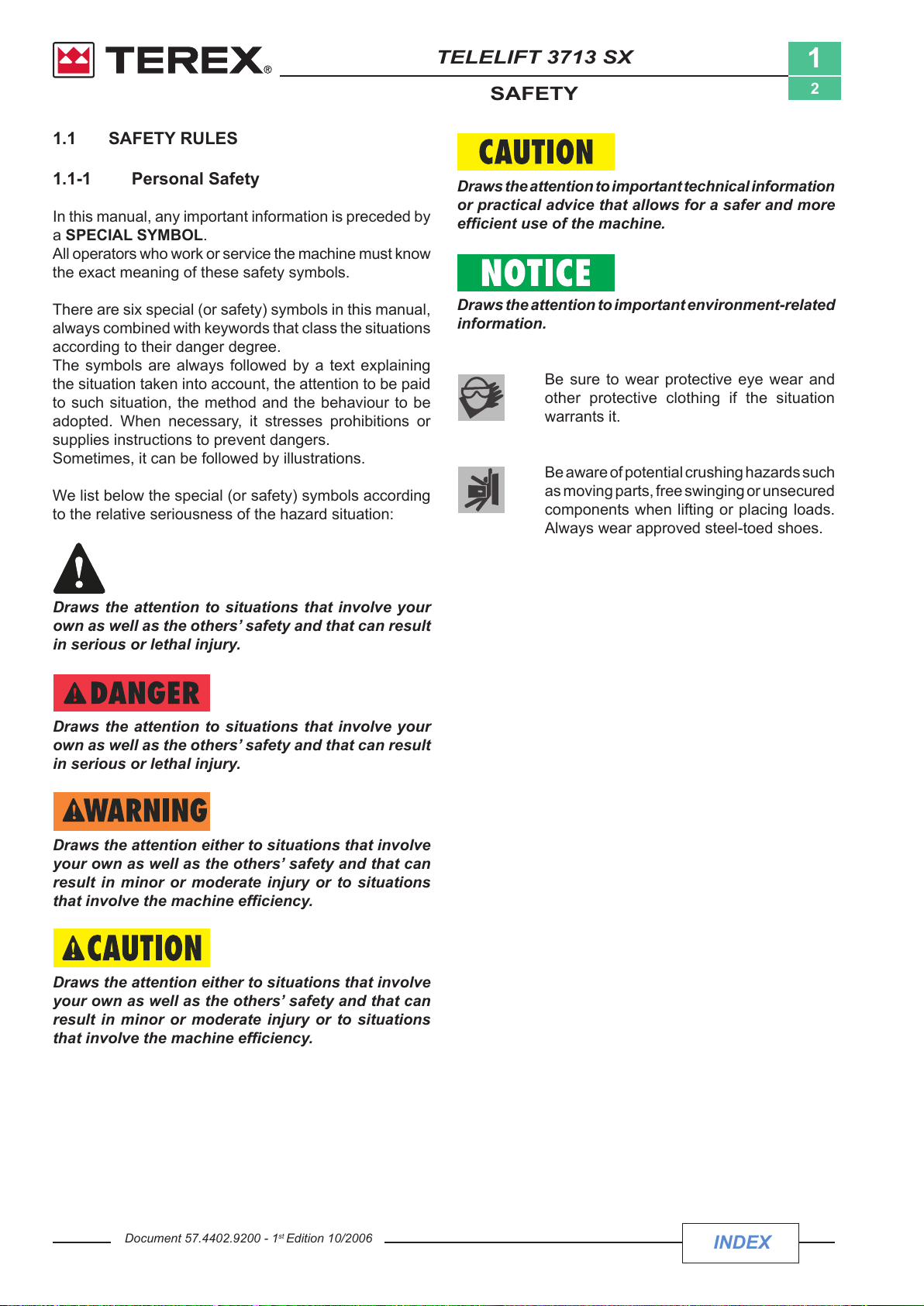
There are six special (or safety) symbols in this manual,
always combined with keywords that class the situations
according to their danger degree.
The symbols are always followed by a text explaining
the situation taken into account, the attention to be paid
to such situation, the method and the behaviour to be
adopted. When necessary, it stresses prohibitions or
supplies instructions to prevent dangers.
Sometimes, it can be followed by illustrations.
We list below the special (or safety) symbols according
to the relative seriousness of the hazard situation:
Draws the attention to situations that involve your
own as well as the others’ safety and that can result
in serious or lethal injury.
Draws the attention to important technical information
or practical advice that allows for a safer and more
efcient use of the machine.
Draws the attention to important environment-related
information.
Be sure to wear protective eye wear and
other protective clothing if the situation
warrants it.
Be aware of potential crushing hazards such
as moving parts, free swinging or unsecured
components when lifting or placing loads.
Always wear approved steel-toed shoes.
Draws the attention to situations that involve your
own as well as the others’ safety and that can result
in serious or lethal injury.
Draws the attention either to situations that involve
your own as well as the others’ safety and that can
result in minor or moderate injury or to situations
that involve the machine efciency.
Draws the attention either to situations that involve
your own as well as the others’ safety and that can
result in minor or moderate injury or to situations
that involve the machine efciency.
Document 57.4402.9200 - 1
st
Edition 10/2006
INDEX
Courtesy of Crane.Market
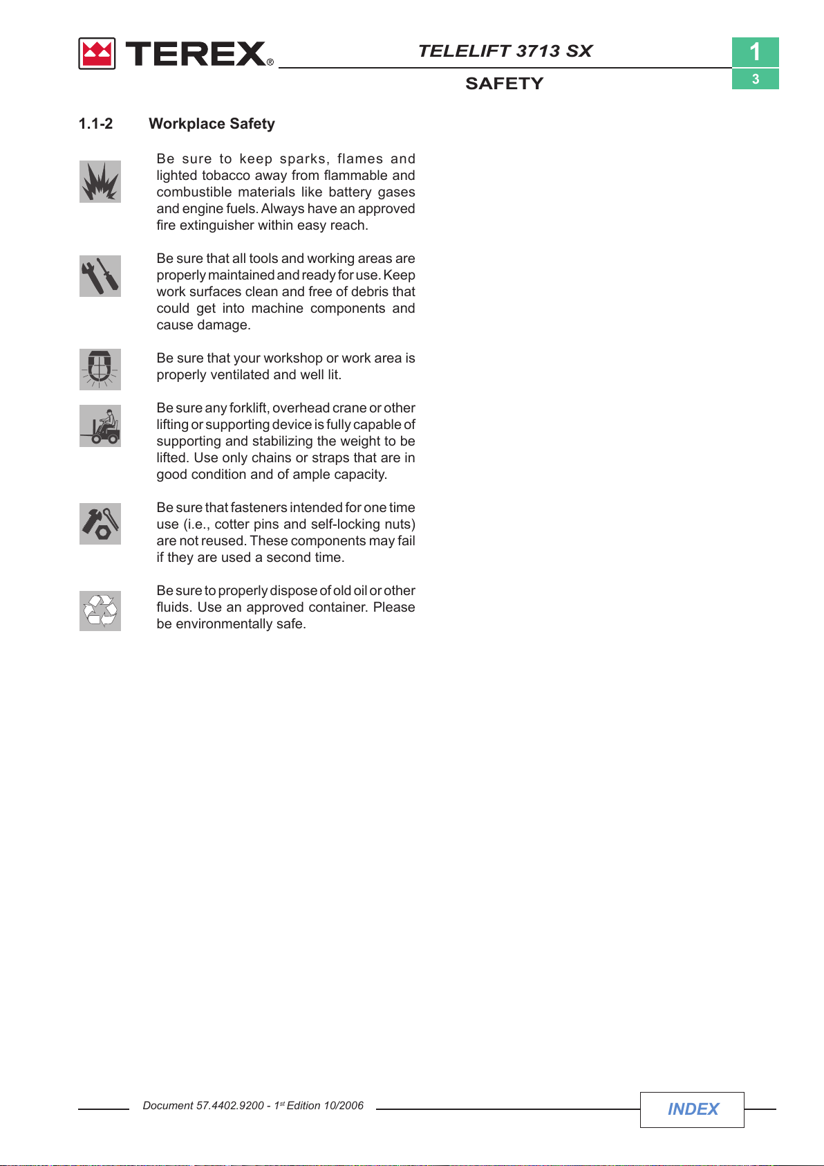
1.1-2 Workplace Safety
Be sure to keep sparks, flames and
lighted tobacco away from ammable and
combustible materials like battery gases
and engine fuels. Always have an approved
re extinguisher within easy reach.
Be sure that all tools and working areas are
properly maintained and ready for use. Keep
work surfaces clean and free of debris that
could get into machine components and
cause damage.
Be sure that your workshop or work area is
properly ventilated and well lit.
Be sure any forklift, overhead crane or other
lifting or supporting device is fully capable of
supporting and stabilizing the weight to be
lifted. Use only chains or straps that are in
good condition and of ample capacity.
TELELIFT 3713 SX
SAFETY
1
3
Be sure that fasteners intended for one time
use (i.e., cotter pins and self-locking nuts)
are not reused. These components may fail
if they are used a second time.
Be sure to properly dispose of old oil or other
uids. Use an approved container. Please
be environmentally safe.
Document 57.4402.9200 - 1
st
Edition 10/2006
INDEX
Courtesy of Crane.Market
TELELIFT 3713 SX
SAFETY
1
4
1.2 GENERAL REMARKS
Most accidents occurring while working, servicing or
maintaining operation machines, are caused by not
complying with the basic safety precautions.
Therefore, it is necessary to pay steady attention to
the potential hazards and the effects that may come of
operations carried out on the machine.
If you recognise hazardous situations, you can
prevent accidents!
For instance, this handbook makes use of special safety
symbols to highlight potentially hazardous situations.
The instructions given in this handbook are the ones
established by TEREXLIFT. They do not exclude other
safe and most convenient ways for the machine
commissioning, operation and maintenance that take
into account the available spaces and means.
If you decide to follow instructions other than those given
in this manual, you must:
• be sure that the operations you are going to carry
out are not explicitly forbidden;
• be sure that the methods are safe and in compliance
with the indications given in this section;
• be sure that the methods cannot damage the machine
directly or indirectly or make it unsafe;
• contact TEREXLIFT Assistance Service for any
suggestion and the necessary written permission.
1.3 SERVICEMEN'S REQUISITES
The operators who use the machine regularly or
occasionally (e.g. for maintenance or transport) shall
have the following requisites:
health:
before and during any operation, operators shall never
take alcoholic beverages, medicines or other substances
that may alter their psycho-physical conditions and,
consequently, their working abilities.
physical:
good eyesight, acute hearing, good co-ordination and
ability to carry out all required operations in a safe way,
according to the instructions of this manual.
mental:
ability to understand and apply the rules, regulations and
safety precautions. They shall be careful and sensible
for their own as well as for the others’ safety and shall
desire to carry out the work correctly and in a responsible
way.
emotional:
they shall keep calm and always be able to evaluate their
own physical and mental conditions.
training:
they shall read and familiarise with this handbook, its
enclosed graphs and diagrams, the identication and
hazard warning plates. They shall be skilled and trained
about the machine use.
Do not hesitate to pose questions if you are in doubt!
Contact TEREXLIFT: the assistance service is at
your disposal. Addresses, phone and fax numbers
are given in the cover and in the title-page of this
manual.
Document 57.4402.9200 - 1
st
Edition 10/2006
It is recommended to take part in at least one technical
training course organised by TEREXLIFT Assistance
Ofce.
Ordinary and extraordinary maintenance of the
machineare quite complex from a technical point
of view and should be performed by an authoirsed
service centre.
INDEX
Courtesy of Crane.Market
TELELIFT 3713 SX
SAFETY
1
5
1.3-1 PERSONAL PROTECTIVE EQUIPMENT
During work, but especially when maintaining or repairing
the machine, operators must wear suitable protective
clothing and equipment:
• Overalls or any other comfortable garments.
Operators should wear neither clothes with large
sleeves nor objects that can get stuck in moving parts
of the machine
• Protective helmet when working under or in the
vicinity of suspended load
• Protective gloves
• Working shoes
• Breathing set (or dust mask)
• Ear-protectors or equivalent equipment
• Goggles or facial screen.
Use only type-approved protective equipment in
good condition.
1.4 SAFETY PRECAUTIONS
Read and understand the following safety instructions
before servicing the machine.
The following list contains safety rules which must
absolutely be obeyed to prevent accidents and
injuries.
1.4-1 WORKING AREA
• Make sure the area all around the machine is safe.
Always be aware of potential risks.
• During work, keep the working area in order. Never
leave objects scattered: they could hinder the
machine movements and represent a danger for
personnel.
1.4-2 PRECAUTIONS DURING WORK
• Do not walk or stop under raised loads or machine
parts supported by hydraulic cylinders or ropes
only.
• Keep the machine handholds and access steps
always clean from oil, grease or dirt to prevent falls
or slips.
• When entering/leaving the cab or other raised parts,
always face the machine; never turn the back.
• When carrying out operations at hazardous heights
(over 3 meters from the ground), always use type-
approved safety belts or fall preventing devices.
• Do not enter/leave the machine when it is running.
• Before servicing the engine, let its parts cool down.
• Do not leave the driving place when the machine is
running.
• Neither stop nor carry out interventions under or
between the machine wheels when engine is running.
When maintenance in this area is needed, stop the
engine, engage the parking brake and chock the
wheels to prevent accidental movements.
• Do not carry out maintenance or repair works without
a sufcient lighting.
• When using the machine lights, the beam should be
oriented in order not to blind the personnel at work.
• Before applying voltage to electric cables or
components, ensure they are properly connected
and efcient.
• Do not carry out interventions on electric components
with voltage over 48V.
Document 57.4402.9200 - 1
st
Edition 10/2006
INDEX
Courtesy of Crane.Market
• Do not connect wet plugs or sockets.
• Signs and stickers shall never be removed, hidden
or become unreadable.
• Except for maintenance purposes, do not remove
safety devices, covers, guards,. Should their removal
be necessary, stop the engine, remove them with
the greatest care and always remember to ret them
before starting the engine and using the machine
again.
• Aleays stop the engine and disconnect the batteries
before maintenance or service.
• Do not lubricate, clean or adjust moving parts.
• Do not carry out operations manually when specic
tools are provided for this purpose.
• Absolutely avoid to use tools in bad conditions or in
an improper way.
• Before carrying out operations on hydraulic lines
under pressure (hydraulic oil, compressed air) and/or
before disconnecting hydraulic components, ensure
the relevant line has been previously depressurised
and does not contain any hot uid.
TELELIFT 3713 SX
SAFETY
Treatment and disposal of used oils is subject to
federal, national and local laws and regulations.
Collect and deliver these wastes to authorised
centres.
• Use the assistance of a second person to handle
loads weighing 30 to 50 kg.
• For loads over 50 kg, the use of special hoisting
equipment in good condition and equipped as per
enforced regulations is mandatory.
1
6
Any intervention on the hydraulic or pneumatic
circuit must be carried out by authorised personnel.
Before any operation on lines under pressure, release
any residual pressure from the circuit.
Do not use your ngers to check for pressure leaks.
Fine jets of air, oil or fuel can injure you.
• Neither smoke nor use open ames if there is a risk
of re or close to fuel, oil or batteries.
• Do not leave fuel cans or bottles in unsuitable
places.
• Do not empty catalytic mufers or other vessels
containing burning materials without taking the
necessary precautions.
• Carefully handle all flammable or dangerous
substances.
• After any maintenance or repair work, make sure
that no tool, cloth or other object has been left within
compartments with moving parts or in which suction
and cooling air circulates.
•
Never give orders to several people at a ime. Instructions
and signs must be given by one person only.
• Always pay the due attention to the instructions given
by the foreman.
• Never distract the operator during working phases
or crucial manoeuvres.
• Do not call an operator suddenly, if unnecessary.
• Do not frighten an operator or throw objects by no
means.
• After work, never leave the machine under potentially
dangerous conditions.
Document 57.4402.9200 - 1
st
Edition 10/2006
INDEX
Courtesy of Crane.Market
TELELIFT 3713 SX
TECHNICAL SPECIFICATIONS
2
1
Section 2
TECHNICAL SPECIFICATIONS
SECTION INDEX
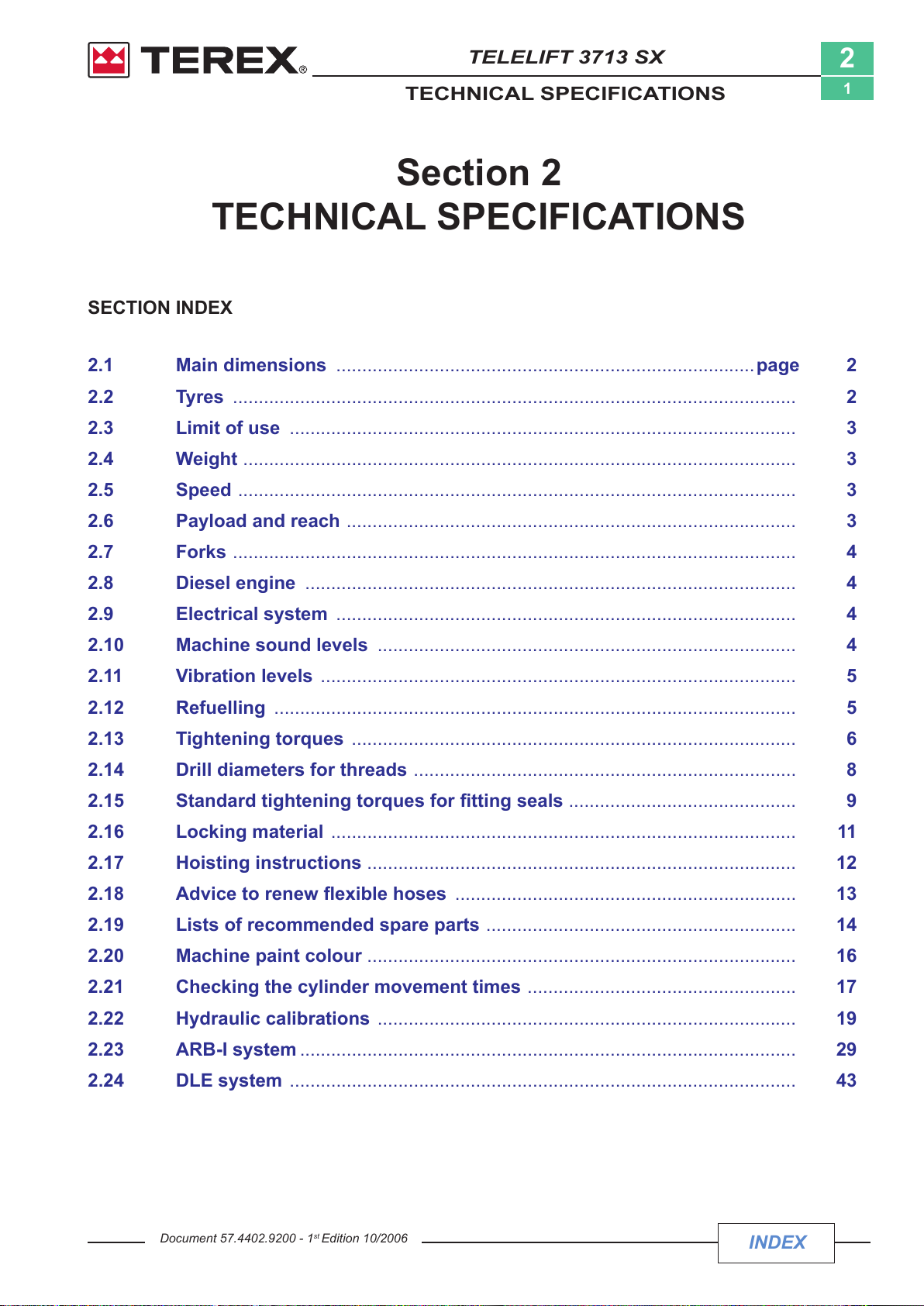
2.1 Main dimensions .................................................................................page 2
2.2 Tyres
2.3 Limit of use
2.4 Weight
2.5 Speed
2.6 Payload and reach
2.7 Forks
2.8 Diesel engine
2.9 Electrical system
2.10 Machine sound levels
2.11 Vibration levels
2.12 Refuelling
2.13 Tightening torques
2.14 Drill diameters for threads
2.15 Standardtighteningtorquesforttingseals
2.16 Locking material
............................................................................................................. 2
.................................................................................................. 3
........................................................................................................... 3
............................................................................................................ 3
....................................................................................... 3
............................................................................................................. 4
............................................................................................... 4
......................................................................................... 4
................................................................................. 4
............................................................................................ 5
..................................................................................................... 5
...................................................................................... 6
.......................................................................... 8
.......................................................................................... 11
............................................ 9
2.17 Hoisting instructions
2.18 Advicetorenewexiblehoses
2.19 Lists of recommended spare parts
2.20 Machine paint colour
2.21 Checking the cylinder movement times
2.22 Hydraulic calibrations
2.23 ARB-I
2.24 DLE system
Document 57.4402.9200 - 1
system ................................................................................................ 29
.................................................................................................. 43
st
................................................................................... 12
.................................................................. 13
............................................................ 14
................................................................................... 16
................................................................................. 19
Edition 10/2006
.................................................... 17
INDEX
Courtesy of Crane.Market
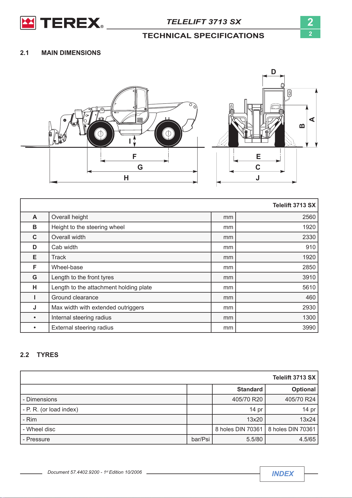
2.1 MAIN DIMENSIONS
I
F
G
H
E
D
B
A
C
J
TELELIFT 3713 SX
TECHNICAL SPECIFICATIONS
2
2
Telelift 3713 SX
A Overall height mm 2560
B Height to the steering wheel mm 1920
C Overall width mm 2330
D Cab width mm 910
E Track mm 1920
F Wheel-base mm 2850
G Length to the front tyres mm 3910
H Length to the attachment holding plate mm 5610
I Ground clearance mm 460
J Max width with extended outriggers mm 2930
• Internal steering radius mm 1300
• External steering radius mm 3990
2.2 TYRES
Telelift 3713 SX
Standard Optional
- Dimensions 405/70 R20 405/70 R24
- P. R. (or load index) 14 pr 14 pr
- Rim 13x20 13x24
- Wheel disc
- Pressure bar/Psi 5.5/80 4.5/65
8 holes DIN 70361 8 holes DIN 70361
INDEX
Courtesy of Crane.Market
Document 57.4402.9200 - 1
st
Edition 10/2006
TELELIFT 3713 SX
TECHNICAL SPECIFICATIONS
2
3
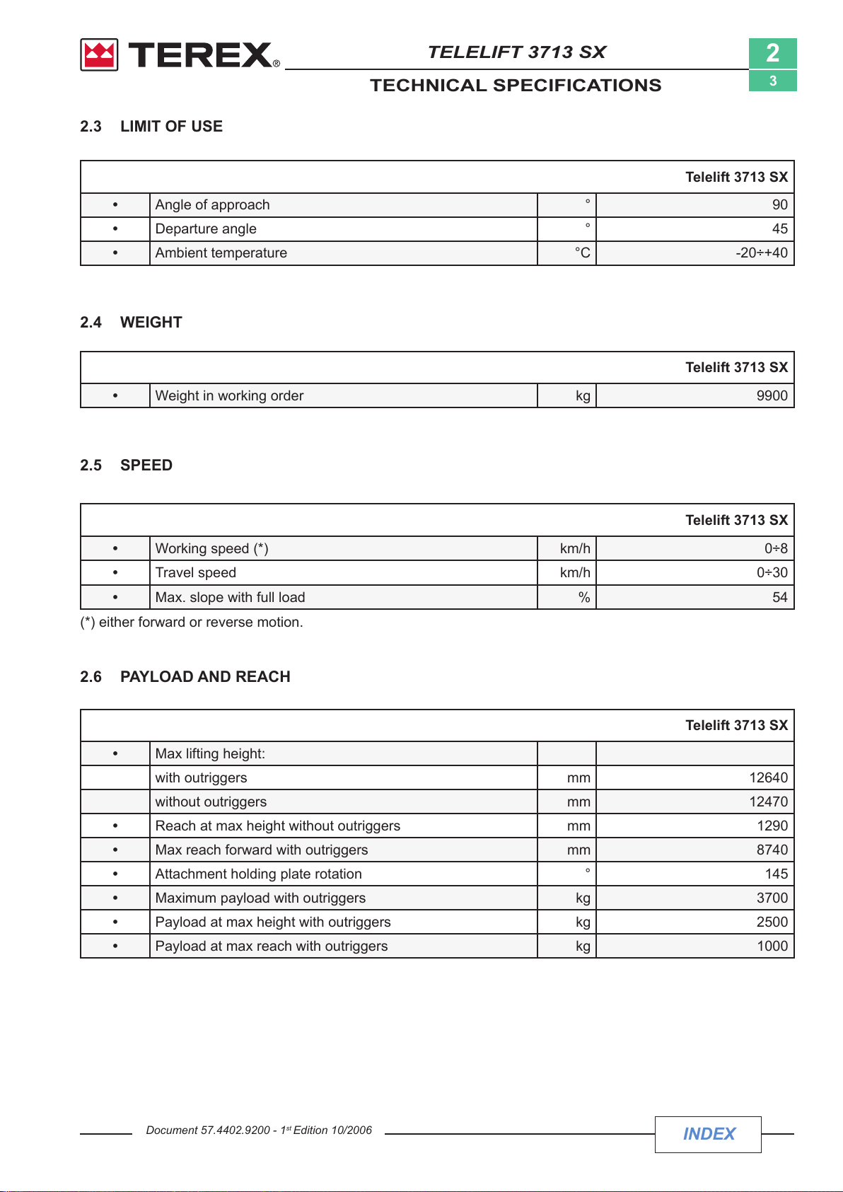
2.3 LIMIT OF USE
Telelift 3713 SX
• Angle of approach ° 90
• Departure angle ° 45
• Ambient temperature °C -20÷+40
2.4 WEIGHT
TELELIFT 3512 4010
Telelift 3713 SX
• Weight in working order kg 9900
2.5 SPEED
Telelift 3713 SX
• Working speed (*) km/h 0÷8
• Travel speed km/h 0÷30
• Max. slope with full load % 54
(*) either forward or reverse motion.
TELELIFT 3512 4010
2.6 PAYLOAD AND REACH
Telelift 3713 SX
• Max lifting height:
with outriggers mm 12640
without outriggers mm 12470
• Reach at max height without outriggers mm 1290
• Max reach forward with outriggers mm 8740
• Attachment holding plate rotation ° 145
• Maximum payload with outriggers kg 3700
• Payload at max height with outriggers kg 2500
• Payload at max reach with outriggers kg 1000
Document 57.4402.9200 - 1
st
Edition 10/2006
INDEX
Courtesy of Crane.Market
TELELIFT 3713 SX
TECHNICAL SPECIFICATIONS
2
4
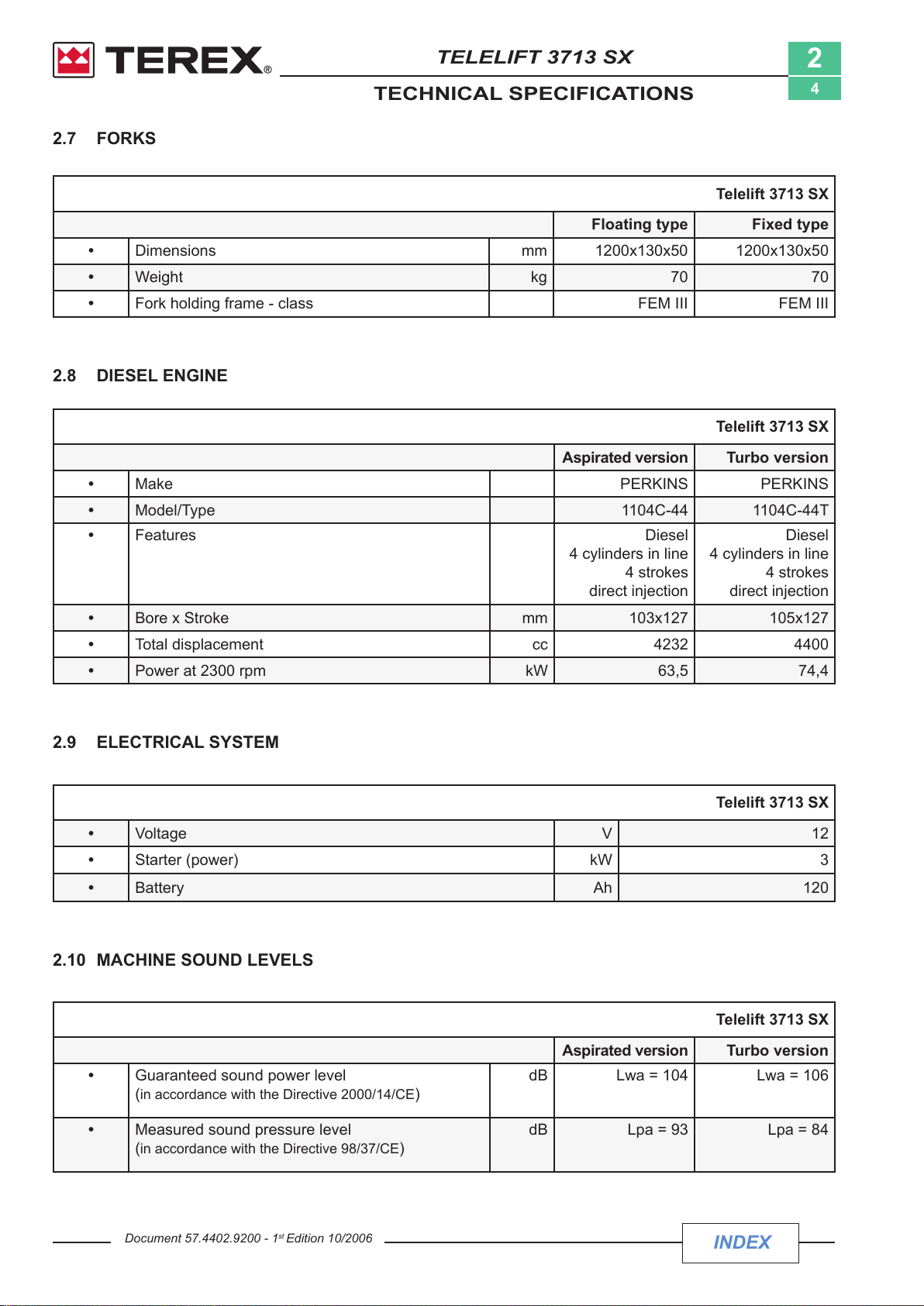
2.7 FORKS
Telelift 3713 SX
Floating type Fixedtype
• Dimensions mm 1200x130x50 1200x130x50
• Weight kg 70 70
• Fork holding frame - class FEM III FEM III
TELELIFT 3512 4010
2.8 DIESEL ENGINE
3512 4010
Telelift 3713 SX
Aspirated version Turbo version
• Make PERKINS PERKINS
• Model/Type 1104C-44 1104C-44T
• Features Diesel
4 cylinders in line
4 strokes
direct injection
• Bore x Stroke mm 103x127 105x127
• Total displacement cc 4232 4400
• Power at 2300 rpm kW 63,5 74,4
TELELIFT 3512 4010
4 cylinders in line
direct injection
Diesel
4 strokes
2.9 ELECTRICAL SYSTEM
Telelift 3713 SX
• Voltage V 12
• Starter (power) kW 3
• Battery Ah 120
TELELIFT 3512 4010
2.10 MACHINE SOUND LEVELS
• Guaranteed sound power level
(in accordance with the Directive 2000/14/CE)
• Measured sound pressure level
(in accordance with the Directive 98/37/CE)
Document 57.4402.9200 - 1
st
Edition 10/2006
Telelift 3713 SX
Aspirated version Turbo version
dB Lwa = 104 Lwa = 106
dB Lpa = 93 Lpa = 84
INDEX
Courtesy of Crane.Market
TELELIFT 3713 SX
TECHNICAL SPECIFICATIONS
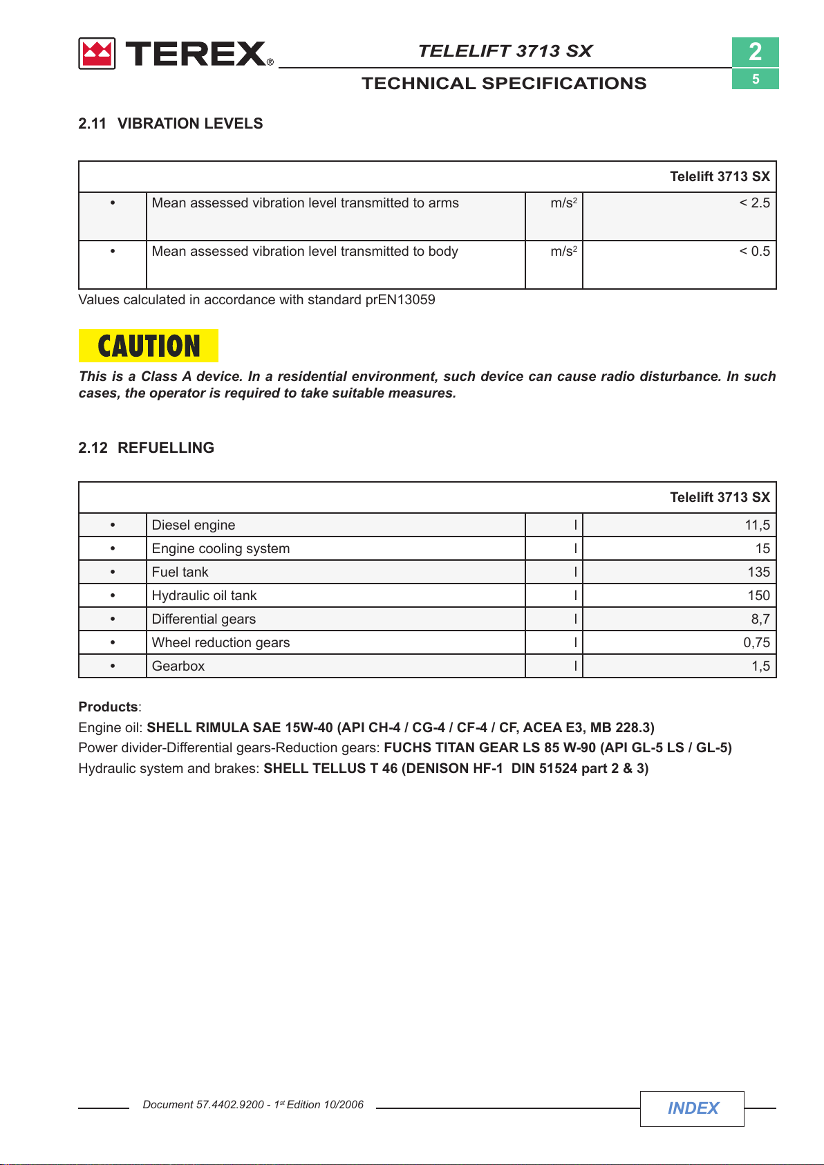
2.11 VIBRATION LEVELS
• Mean assessed vibration level transmitted to arms m/s
2
5
Telelift 3713 SX
2
< 2.5
• Mean assessed vibration level transmitted to body m/s
2
< 0.5
Values calculated in accordance with standard prEN13059
This is a Class A device. In a residential environment, such device can cause radio disturbance. In such
cases, the operator is required to take suitable measures.
2.12 REFUELLING
Telelift 3713 SX
• Diesel engine l 11,5
• Engine cooling system l 15
• Fuel tank l 135
• Hydraulic oil tank l 150
• Differential gears l 8,7
• Wheel reduction gears l 0,75
• Gearbox l 1,5
Products
:
Engine oil: SHELL RIMULA SAE 15W-40 (API CH-4 / CG-4 / CF-4 / CF, ACEA E3, MB 228.3)
Power divider-Differential gears-Reduction gears: FUCHS TITAN GEAR LS 85 W-90 (API GL-5 LS / GL-5)
Hydraulic system and brakes: SHELL TELLUS T 46 (DENISON HF-1 DIN 51524 part 2 & 3)
Document 57.4402.9200 - 1
st
Edition 10/2006
INDEX
Courtesy of Crane.Market
TELELIFT 3713 SX
S
S
8.8
10.9
12.9
TECHNICAL SPECIFICATIONS
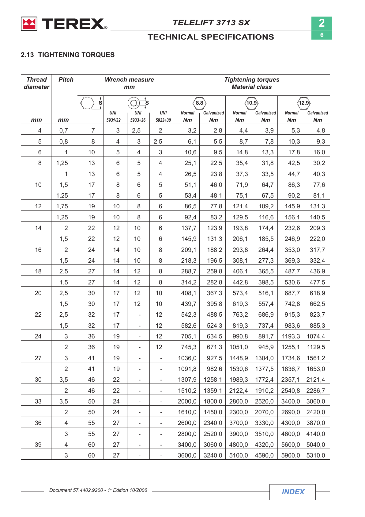
2.13 TIGHTENING TORQUES
Thread Pitch Wrench measure Tightening torques
diameter mm Material class
2
6
mm mm
UNI UNI UNI Normal Galvanized Normal Galvanized Normal Galvanized
5931/32 5933÷36 5923÷30
Nm Nm Nm Nm Nm Nm
4 0,7 7 3 2,5 2 3,2 2,8 4,4 3,9 5,3 4,8
5 0,8 8 4 3 2,5 6,1 5,5 8,7 7,8 10,3 9,3
6 1 10 5 4 3 10,6 9,5 14,8 13,3 17,8 16,0
8 1,25 13 6 5 4 25,1 22,5 35,4 31,8 42,5 30,2
1 13 6 5 4 26,5 23,8 37,3 33,5 44,7 40,3
10 1,5 17 8 6 5 51,1 46,0 71,9 64,7 86,3 77,6
1,25 17 8 6 5 53,4 48,1 75,1 67,5 90,2 81,1
12 1,75 19 10 8 6 86,5 77,8 121,4 109,2 145,9 131,3
1,25 19 10 8 6 92,4 83,2 129,5 116,6 156,1 140,5
14 2 22 12 10 6 137,7 123,9 193,8 174,4 232,6 209,3
1,5 22 12 10 6 145,9 131,3 206,1 185,5 246,9 222,0
16 2 24 14 10 8 209,1 188,2 293,8 264,4 353,0 317,7
1,5 24 14 10 8 218,3 196,5 308,1 277,3 369,3 332,4
18 2,5 27 14 12 8 288,7 259,8 406,1 365,5 487,7 436,9
1,5 27 14 12 8 314,2 282,8 442,8 398,5 530,6 477,5
20 2,5 30 17 12 10 408,1 367,3 573,4 516,1 687,7 618,9
1,5 30 17 12 10 439,7 395,8 619,3 557,4 742,8 662,5
22 2,5 32 17 - 12 542,3 488,5 763,2 686,9 915,3 823,7
1,5 32 17 - 12 582,6 524,3 819,3 737,4 983,6 885,3
24 3 36 19 - 12 705,1 634,5 990,8 891,7 1193,3 1074,4
2 36 19 - 12 745,3 671,3 1051,0 945,9 1255,1 1129,5
27 3 41 19 - - 1036,0 927,5 1448,9 1304,0 1734,6 1561,2
2 41 19 - - 1091,8 982,6 1530,6 1377,5 1836,7 1653,0
30 3,5 46 22 - - 1307,9 1258,1 1989,3 1772,4 2357,1 2121,4
2 46 22 - - 1510,2 1359,1 2122,4 1910,2 2540,8 2286,7
33 3,5 50 24 - - 2000,0 1800,0 2800,0 2520,0 3400,0 3060,0
2 50 24 - - 1610,0 1450,0 2300,0 2070,0 2690,0 2420,0
36 4 55 27 - - 2600,0 2340,0 3700,0 3330,0 4300,0 3870,0
3 55 27 - - 2800,0 2520,0 3900,0 3510,0 4600,0 4140,0
39 4 60 27 - - 3400,0 3060,0 4800,0 4320,0 5600,0 5040,0
3 60 27 - - 3600,0 3240,0 5100,0 4590,0 5900,0 5310,0
Document 57.4402.9200 - 1
st
Edition 10/2006
INDEX
Courtesy of Crane.Market
TELELIFT 3713 SX
8G5S8G
5S
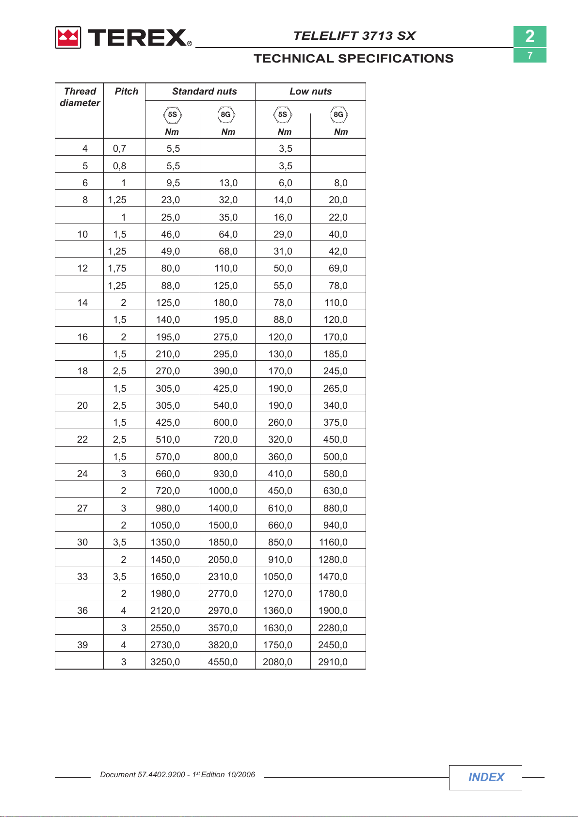
TECHNICAL SPECIFICATIONS
Thread Pitch Standard nuts Low nuts
diameter
Nm Nm Nm Nm
4 0,7 5,5 3,5
5 0,8 5,5 3,5
6 1 9,5 13,0 6,0 8,0
8 1,25 23,0 32,0 14,0 20,0
1 25,0 35,0 16,0 22,0
10 1,5 46,0 64,0 29,0 40,0
1,25 49,0 68,0 31,0 42,0
12 1,75 80,0 110,0 50,0 69,0
1,25 88,0 125,0 55,0 78,0
14 2 125,0 180,0 78,0 110,0
2
7
1,5 140,0 195,0 88,0 120,0
16 2 195,0 275,0 120,0 170,0
1,5 210,0 295,0 130,0 185,0
18 2,5 270,0 390,0 170,0 245,0
1,5 305,0 425,0 190,0 265,0
20 2,5 305,0 540,0 190,0 340,0
1,5 425,0 600,0 260,0 375,0
22 2,5 510,0 720,0 320,0 450,0
1,5 570,0 800,0 360,0 500,0
24 3 660,0 930,0 410,0 580,0
2 720,0 1000,0 450,0 630,0
27 3 980,0 1400,0 610,0 880,0
2 1050,0 1500,0 660,0 940,0
30 3,5 1350,0 1850,0 850,0 1160,0
2 1450,0 2050,0 910,0 1280,0
33 3,5 1650,0 2310,0 1050,0 1470,0
2 1980,0 2770,0 1270,0 1780,0
36 4 2120,0 2970,0 1360,0 1900,0
3 2550,0 3570,0 1630,0 2280,0
39 4 2730,0 3820,0 1750,0 2450,0
3 3250,0 4550,0 2080,0 2910,0
Document 57.4402.9200 - 1
st
Edition 10/2006
INDEX
Courtesy of Crane.Market
TELELIFT 3713 SX
TECHNICAL SPECIFICATIONS
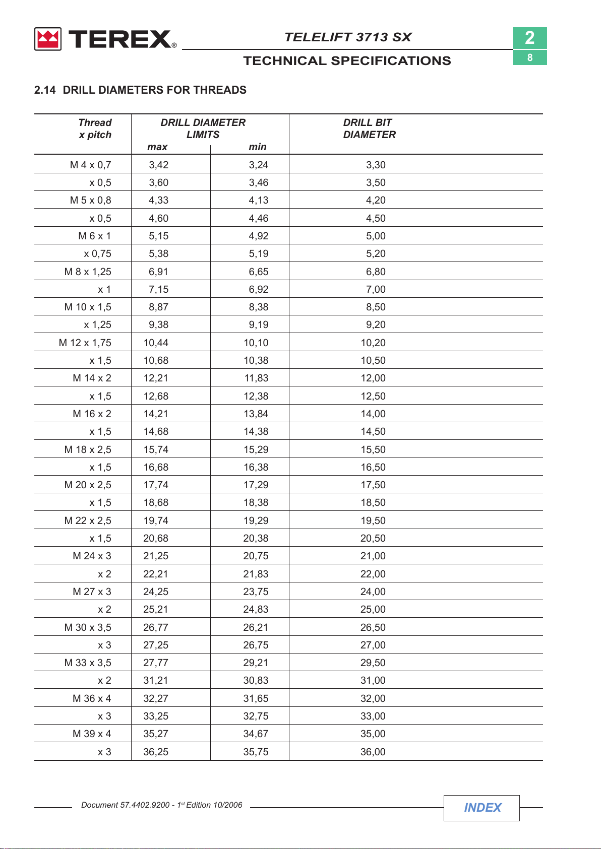
2.14 DRILL DIAMETERS FOR THREADS
Thread DRILL DIAMETER DRILL BIT
x pitch LIMITS DIAMETER
max min
M 4 x 0,7 3,42 3,24 3,30
x 0,5 3,60 3,46 3,50
M 5 x 0,8 4,33 4,13 4,20
x 0,5 4,60 4,46 4,50
M 6 x 1 5,15 4,92 5,00
x 0,75 5,38 5,19 5,20
M 8 x 1,25 6,91 6,65 6,80
x 1 7,15 6,92 7,00
M 10 x 1,5 8,87 8,38 8,50
x 1,25 9,38 9,19 9,20
2
8
M 12 x 1,75 10,44 10,10 10,20
x 1,5 10,68 10,38 10,50
M 14 x 2 12,21 11,83 12,00
x 1,5 12,68 12,38 12,50
M 16 x 2 14,21 13,84 14,00
x 1,5 14,68 14,38 14,50
M 18 x 2,5 15,74 15,29 15,50
x 1,5 16,68 16,38 16,50
M 20 x 2,5 17,74 17,29 17,50
x 1,5 18,68 18,38 18,50
M 22 x 2,5 19,74 19,29 19,50
x 1,5 20,68 20,38 20,50
M 24 x 3 21,25 20,75 21,00
x 2 22,21 21,83 22,00
M 27 x 3 24,25 23,75 24,00
x 2 25,21 24,83 25,00
M 30 x 3,5 26,77 26,21 26,50
x 3 27,25 26,75 27,00
M 33 x 3,5 27,77 29,21 29,50
x 2 31,21 30,83 31,00
M 36 x 4 32,27 31,65 32,00
x 3 33,25 32,75 33,00
M 39 x 4 35,27 34,67 35,00
x 3 36,25 35,75 36,00
Document 57.4402.9200 - 1
st
Edition 10/2006
INDEX
Courtesy of Crane.Market
 Loading...