

Terex TA400 Operation Manual

Operations Manual
TA400
15504854
OHE11151
TEREX Equipment Limited Operations Manual
Original Operating Instructions

This page is intentionally left blank

Operations Manual
TA400
15504854
OHE11151
Issued by;
Customer Support Department
Terex Equipment Limited
Newhouse Industrial Estate
Motherwell, ML1 5RY
Scotland
Tel; +44 (0) 1698 732121
Fax; +44 (0) 1698 503210
http//:constructionsupport.terex.com
www.terex.com
OHE11151
Re-order Part Number
15504854
This controlled document is the original instruction
and should remain with the vehicle at all times.
Revision: October 2012
Dealer:
TEREX Equipment Limited Operations Manual Re-order

This page is intentionally left blank

Operations Manual
TA400
15504854
OHE11151
For further information on the subject matter detailed within this operations manual, please refer to Terex Equipment Limited Service Manuals
and Product Parts Books.
Alternatively, please contact;
Customer Support Department
Terex Equipment Limited
Newhouse Industrial Estate
Motherwell, ML1 5RY
Tel; +44 (0) 1698 732121
Fax; +44 (0) 1698 503210
http://constructionsupport.terex.com
www.terex.com
The illustrations, technical information, data and descriptive text in this
manual, to the best of our knowledge, were correct at the time of print.
The right to change specifications, equipment and maintenance instructions at any time without notice, is reserved as part of the Terex Equipment Limited policy of continuous development and improvement of the
product.
No part of this publication may be reproduced, transmitted in any form electronic, mechanical, photocopying, recording, translating or by any
other means without prior permission of Customer Support Department
- Terex Equipment Limited.
Please refer to TEREX Specification Sheets or consult Factory Representatives to ensure that information is current.
TEREX Equipment Limited Operations Manual - Introduction

This page is intentionally left blank

ONLY TRAINED COMPETENT PERSONNEL
SHOULD BE ALLOWED TO OPERATE THIS
VEHICLE
The operator is responsible and must be
familiar with the contents of the Operations
Manual and any Local / National regulations
prior to operating this vehicle.

This page is intentionally left blank

CALIFORNIA
Proposition 65 Warnings
WARNING: Diesel engine exhaust and
some of its constituents are known to the
State of California to cause cancer, birth
defects, and other reproductive harm.
WARNING: Battery posts, terminals and
related accessories contain lead and lead
compounds, chemicals known to the State of
California to cause cancer and reproductive
harm. Wash hands after handling.

This page is intentionally left blank

Terex Equipment Limited,
Newhouse Industrial Estate,
Motherwell,
Scotland.
ML1 5RY
Name: David Maslin, 2000/14/EC Noise Directive
Address: Newhouse Industrial Estate, 2004/108/EC Electromagnetic Compatibilty
Motherwell, Scotland. ML1 5RY
2006/42/EC Machinery Directive
97/68/EC Emissions Directive
MAKE:
FULL QUALITY ASSURANCE (Annex VIII):
L.R.Q.A. Ltd.,
Hiramford,
Middlemarch Office Village,
Siskin Drive,
Coventry,
CV3 4FJ.
England
SIGNATURE:
DATE:
UNIT SERIAL NUMBER:
WE DECLARE THAT THE ABOVE MACHINERY FULFILLS ALL THE RELEVANT PROVISIONS OF THE ABOVE
DIRECTIVES
CERTIFICATE NUMBER:
TA400 Articulated Dump Truck
INSPECTOR:
FOR AND ON BEHALF OF THE MANUFACTURER:
NAME:
Paul Douglas
POSITION:
General Manager
PLACE:
Motherwell, Scotland
MANUFACTURER'S NAME AND FULL ADDRESS:
EC DECLARATION OF CONFORMITY
DIRECTIVES COMPLIED WITH:
PERSON AUTHORISED TO COMPILE TECHNICAL FILE
DATE OF MANUFACTURE:
LRQ 0925301/B
DESCRIPTION OF MACHINERY:
TEREX
MODEL/DESIGNATION:

SPARE PARTS STATEMENT
When carrying out repairs, alterations or fitting attachments, it is important that only
genuine spare parts are used to ensure the operating safety of the machine is not
impaired.
It is only by using genuine parts that the technical requirements stipulated by the
manufacturer can be maintained.
If a General Operating Approval is issued for this machine, it may be considered null
and void if non-genuine parts are used.
Terex Equipment Limited,
Newhouse Industrial Estate,
Motherwell,
Scotland.
ML1 5RY
Name: David Maslin, 2000/14/EC Noise Directive
Address: Newhouse Industrial Estate, 2004/108/EC Electromagnetic Compatibilty
Motherwell, Scotland. ML1 5RY
2006/42/EC Machinery Directive
97/68/EC Emissions Directive
MAKE:
FULL QUALITY ASSURANCE (Annex VIII):
L.R.Q.A. Ltd.,
Hiramford,
Middlemarch Office Village,
Siskin Drive,
Coventry,
CV3 4FJ.
England
SIGNATURE:
DATE:
UNIT SERIAL NUMBER:
WE DECLARE THAT THE ABOVE MACHINERY FULFILLS ALL THE RELEVANT PROVISIONS OF THE ABOVE
DIRECTIVES
CERTIFICATE NUMBER:
TA400 Articulated Dump Truck
INSPECTOR:
FOR AND ON BEHALF OF THE MANUFACTURER:
NAME:
Paul Douglas
POSITION:
General Manager
PLACE:
Motherwell, Scotland
MANUFACTURER'S NAME AND FULL ADDRESS:
EC DECLARATION OF CONFORMITY
DIRECTIVES COMPLIED WITH:
PERSON AUTHORISED TO COMPILE TECHNICAL FILE
DATE OF MANUFACTURE:
LRQ 0925301/B
DESCRIPTION OF MACHINERY:
TEREX
MODEL/DESIGNATION:

SPARE PARTS STATEMENT
When carrying out repairs, alterations or fitting attachments, it is important that only
genuine spare parts are used to ensure the operating safety of the machine is not
impaired.
It is only by using genuine parts that the technical requirements stipulated by the
manufacturer can be maintained.
If a General Operating Approval is issued for this machine, it may be considered null
and void if non-genuine parts are used

CONTENTS
1 INTRODUCTION
Introduction. . . . . . . . . . . . . . . . . . . . . . . . . . . . . . . . . 1-1
Safety Alert Symbol . . . . . . . . . . . . . . . . . . . . . . . . . . 1-1
Hazard Classification . . . . . . . . . . . . . . . . . . . . . . . . . 1-1
Intended Use of the Machine . . . . . . . . . . . . . . . . . . . 1-2
Product Identification No. . . . . . . . . . . . . . . . . . . . . . . 1-3
Spare Part Statement. . . . . . . . . . . . . . . . . . . . . . . . . 1-3
Theft Deterrent Practices.. . . . . . . . . . . . . . . . . . . . . . 1-4
2 SAFETY
General. . . . . . . . . . . . . . . . . . . . . . . . . . . . . . . . . . . . 2-4
Articulation and Oscillation Lock. . . . . . . . . . . . . . . . . 2-5
Machine Lifting Precautions . . . . . . . . . . . . . . . . . . . . 2-5
Machine Tie Down Precautions . . . . . . . . . . . . . . . . . 2-5
Preventing Fire Hazards. . . . . . . . . . . . . . . . . . . . . . . 2-6
Mounting and Dismounting. . . . . . . . . . . . . . . . . . . . . 2-7
Pre-Starting . . . . . . . . . . . . . . . . . . . . . . . . . . . . . . . . 2-8
Starting . . . . . . . . . . . . . . . . . . . . . . . . . . . . . . . . . . . . 2-8
Operating . . . . . . . . . . . . . . . . . . . . . . . . . . . . . . . . . . 2-8
Roading . . . . . . . . . . . . . . . . . . . . . . . . . . . . . . . . . . . 2-10
Lubrication and Servicing . . . . . . . . . . . . . . . . . . . . . . 2-11
Scrapping the Machine. . . . . . . . . . . . . . . . . . . . . . . . 2-12
Mirror and CCTV . . . . . . . . . . . . . . . . . . . . . . . . . . . . 2-13
Wheels And Tyres . . . . . . . . . . . . . . . . . . . . . . . . . . . 2-15
Avoid Tyre Explosion Hazard . . . . . . . . . . . . . . . . . . . 2-16
Emergency Exit from Cab. . . . . . . . . . . . . . . . . . . . . . 2-17
Decals And Instruction Plates. . . . . . . . . . . . . . . . . . . 2-18
3 CONTROLS AND OPERATING
Controls and Instruments . . . . . . . . . . . . . . . . . . . . . . 3-3
Fuse / Relay Box . . . . . . . . . . . . . . . . . . . . . . . . . . . . 3-4
Basic Data . . . . . . . . . . . . . . . . . . . . . . . . . . . . . . . . . 3-9
Warning Lights and Symbols . . . . . . . . . . . . . . . . . . . 3-10
Instruments. . . . . . . . . . . . . . . . . . . . . . . . . . . . . . . . . 3-13
Menu Screen and Buttons . . . . . . . . . . . . . . . . . . . . . 3-14
Switches . . . . . . . . . . . . . . . . . . . . . . . . . . . . . . . . . . . 3-18
Controls . . . . . . . . . . . . . . . . . . . . . . . . . . . . . . . . . . . 3-21
Heater. . . . . . . . . . . . . . . . . . . . . . . . . . . . . . . . . . . . . 3-22
Air Conditioning . . . . . . . . . . . . . . . . . . . . . . . . . . . . . 3-22
Operator’s Seat Air Suspension . . . . . . . . . . . . . . . . . 3-23
Operator’s Seat Operation . . . . . . . . . . . . . . . . . . . . . 3-24
Seat Belt. . . . . . . . . . . . . . . . . . . . . . . . . . . . . . . . . . . 3-26
Machine Controls . . . . . . . . . . . . . . . . . . . . . . . . . . . . 3-27
Braking . . . . . . . . . . . . . . . . . . . . . . . . . . . . . . . . . . . . 3-27
Transmission Retarder . . . . . . . . . . . . . . . . . . . . . . . . 3-28
Engine Brake . . . . . . . . . . . . . . . . . . . . . . . . . . . . . . . 3-29
Engine . . . . . . . . . . . . . . . . . . . . . . . . . . . . . . . . . . . . 3-30
Electronic Foot Pedals . . . . . . . . . . . . . . . . . . . . . . . . 3-30
PDE Fuel Injection System. . . . . . . . . . . . . . . . . . . . . 3-31
Description . . . . . . . . . . . . . . . . . . . . . . . . . . . . . . . . . 3-31

This Page is Intentionally Left Blank

3 CONTROLS AND OPERATING (Continued)
Allison Series 4500 Automatic Shift Transmission. . . 3-42
4th GEN Shift Controller. . . . . . . . . . . . . . . . . . . . . . . 3-43
Drop Box. . . . . . . . . . . . . . . . . . . . . . . . . . . . . . . . . . . 3-50
Differential Lock.. . . . . . . . . . . . . . . . . . . . . . . . . . . . . 3-51
Hydraulic Controls . . . . . . . . . . . . . . . . . . . . . . . . . . . 3-52
Steering . . . . . . . . . . . . . . . . . . . . . . . . . . . . . . . . . . . 3-53
Body Control. . . . . . . . . . . . . . . . . . . . . . . . . . . . . . . . 3-54
Tilting Cab . . . . . . . . . . . . . . . . . . . . . . . . . . . . . . . . . 3-55
Hood. . . . . . . . . . . . . . . . . . . . . . . . . . . . . . . . . . . . . . 3-56
4 OPERATING THE MACHINE
Pre-Starting Inspection. . . . . . . . . . . . . . . . . . . . . . . . 4-3
Component Checks . . . . . . . . . . . . . . . . . . . . . . . . . . 4-3
Engine Operation . . . . . . . . . . . . . . . . . . . . . . . . . . . . 4-6
Starting the Engine. . . . . . . . . . . . . . . . . . . . . . . . . . . 4-7
Starting the Engine With Jumper Cables . . . . . . . . . . 4-9
Pre-Operating Checks . . . . . . . . . . . . . . . . . . . . . . . . 4-10
Brake Function Checks . . . . . . . . . . . . . . . . . . . . . . . 4-11
Driving And Stopping . . . . . . . . . . . . . . . . . . . . . . . . . 4-12
Stopping the Engine . . . . . . . . . . . . . . . . . . . . . . . . . . 4-14
Parking . . . . . . . . . . . . . . . . . . . . . . . . . . . . . . . . . . . . 4-15
5 WORKING THE MACHINE
Working the Machine . . . . . . . . . . . . . . . . . . . . . . . . . 5-3
Loading. . . . . . . . . . . . . . . . . . . . . . . . . . . . . . . . . . . . 5-3
Hauling . . . . . . . . . . . . . . . . . . . . . . . . . . . . . . . . . . . . 5-5
Dumping . . . . . . . . . . . . . . . . . . . . . . . . . . . . . . . . . . . 5-6
Empty Return . . . . . . . . . . . . . . . . . . . . . . . . . . . . . . . 5-7
6 ROADING
Roading . . . . . . . . . . . . . . . . . . . . . . . . . . . . . . . . . . . 6-3
General. . . . . . . . . . . . . . . . . . . . . . . . . . . . . . . . . . . . 6-3
Preparation Prior to Roading . . . . . . . . . . . . . . . . . . . 6-3
In Case of Trouble . . . . . . . . . . . . . . . . . . . . . . . . . . . 6-4
7 MOVING A DISABLED MACHINE
Moving a Disabled Machine . . . . . . . . . . . . . . . . . . . . 7-3
8 LUBRICATION AND SERVICING
Safety . . . . . . . . . . . . . . . . . . . . . . . . . . . . . . . . . . . . . 8-3
Lubrications and Servicing . . . . . . . . . . . . . . . . . . . . . 8-4
Lubrications and Service Chart . . . . . . . . . . . . . . . . . 8-5
Miscellaneous Servicing Information . . . . . . . . . . . . . 8-8
Recommended Lubricants . . . . . . . . . . . . . . . . . . . . . 8-11
Specific Information for Tier 4 Engine .. . . . . . . . . . . . 8-19
9 TECHNICAL DATA
TA400. . . . . . . . . . . . . . . . . . . . . . . . . . . . . . . . . . . . . 9-3
10 SYMBOL IDENTIFICATION . . . . . . . . . . . . . . . . . . . 10-3

This Page is Intentionally Left Blank
Introduction
1-1
INTRODUCTION
This manual is provided as a guide to familiarize the operator and service
personnel with the controls, recommended inspections, start-up, operating,
shutdown and parking procedures for the Terex articulated trucks. It is
essential that operators read and understand the manual before operating the
machine.
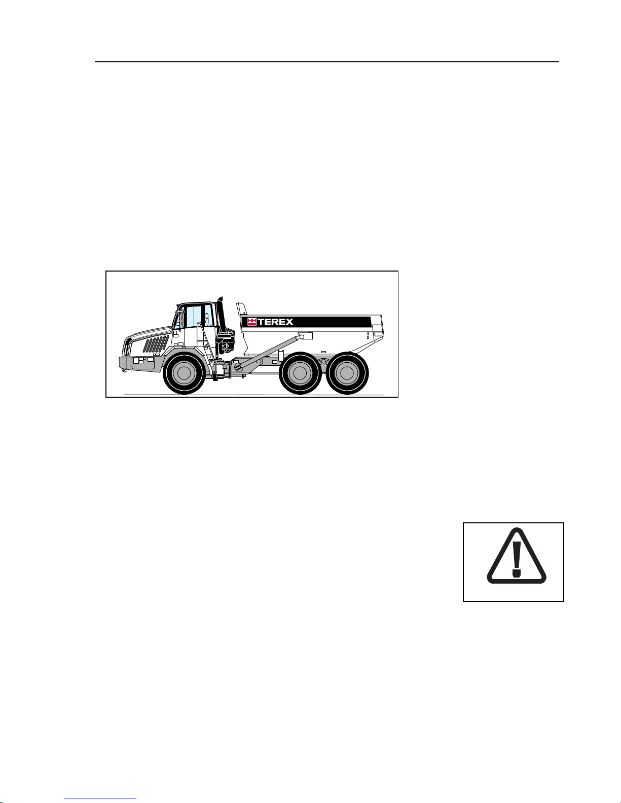
The Terex articulated haulers are 3 axle types with an oscillation and
articulation pivot joint between the tractor and trailer units. Articulation is
achieved by frame steering. The machine has part time or full time 6 wheel
drive controlled by the operator. The machine range has the capability to carry
a maximum payload from 27.5 US ton to 41.9 US ton (25 tonnes to 38 tonnes)
or a heaped capacity of between 20.3 yd3 to 30.3 yd3 (15.5 m3 to 23.3 m3).
SAFETY PRECAUTIONS
The machine should be properly operated and maintained to keep it in a safe,
efficient operating condition. Be sure that all controls are free of mud, grease,
or other matter that might cause slips hazardous to the operator, service
personnel or equipment. Report all malfunctions to those responsible for
maintenance, and, do not operate the equipment until corrected. Normal
service or maintenance performed as required can prevent unexpected and
unnecessary downtime.
Safety Alert Symbol
The Safety Alert System identifies important safety messages in this manual.
When you see this symbol, BE ALERT! Your safety is involved. Carefully read
the message that follows and inform other operators.
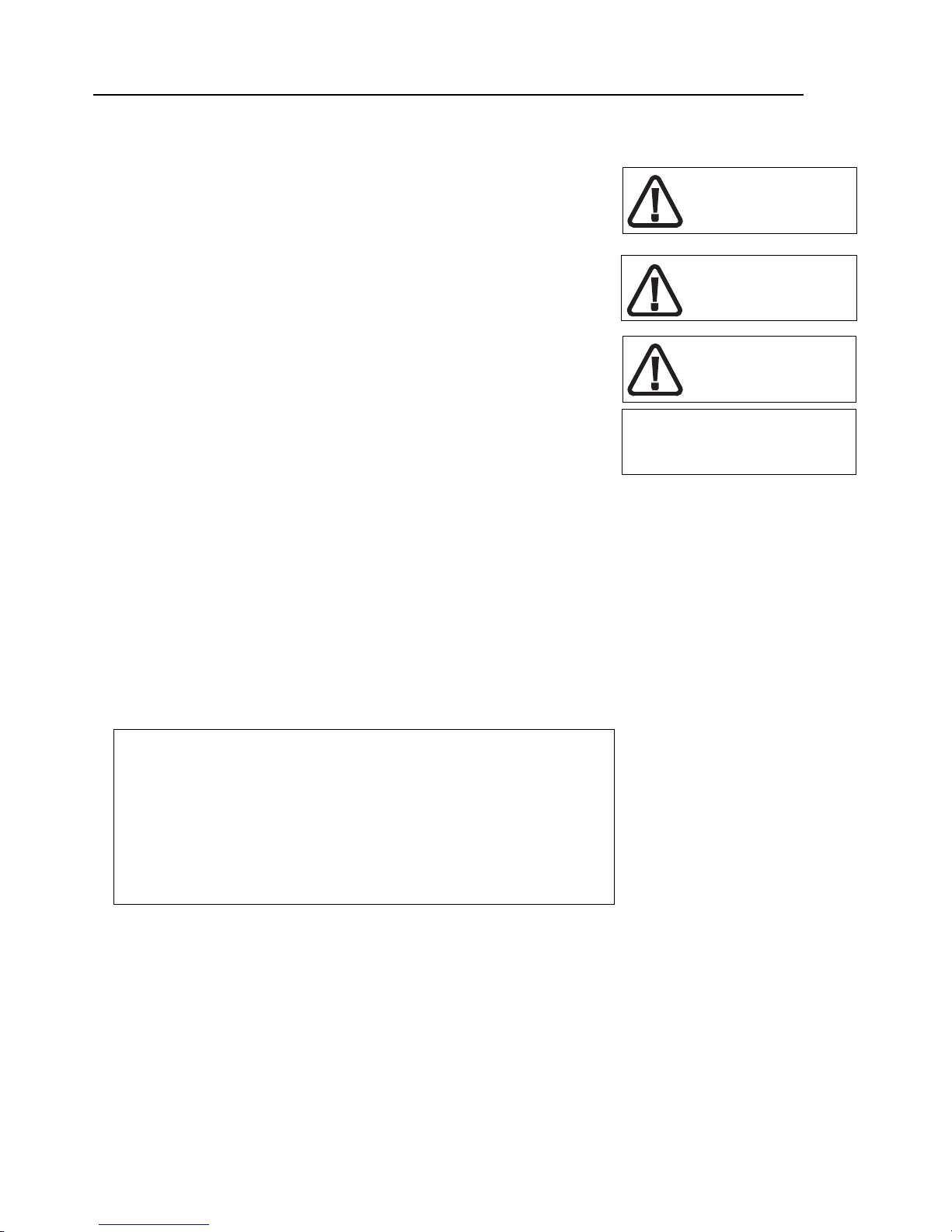
Hazard Classification
A multi-tiered hazard classification system is used to communicate potential
personal injury hazards. The following signal words used with the safety alert
symbol indicate a specific level of severity of the potential hazard. Signal
words used without the safety alert symbol relate to property damage and
protection only. All are used as attention getting devices throughout this
manual as well as on decals and labels fixed to the machinery to assist in
potential hazard recognition and prevention.
MOT00672
Safety alert symbol
Introduction
1-2
DANGER indicates an imminently hazardous situation which, if not avoided,
will result in death or serious injury.
WARNING indicates a potentially hazardous situation which, if not avoided,
could result in death or serious injury.
CAUTION indicates a potentially hazardous situation which, if not avoided,
may result in minor or moderate injury.
CAUTION used without the safety alert symbol indicates a potentially
hazardous situation which, if not avoided, may result in property damage.
INTENDED USE OF MACHINE
This product and its approved attachments are designed to perform the
following functions.
1.Loading
2.Hauling
3.Spreading
USE OTHER THAN INTENDED
CAUTION
Any use other than that stated in “Intended use” shall be considered
impermissible.
The manufacturer shall not be held liable for any resulting damage. The
risk is borne by the user alone.
DANGER
WARNING
CAUTION
CAUTION
Introduction
1-3
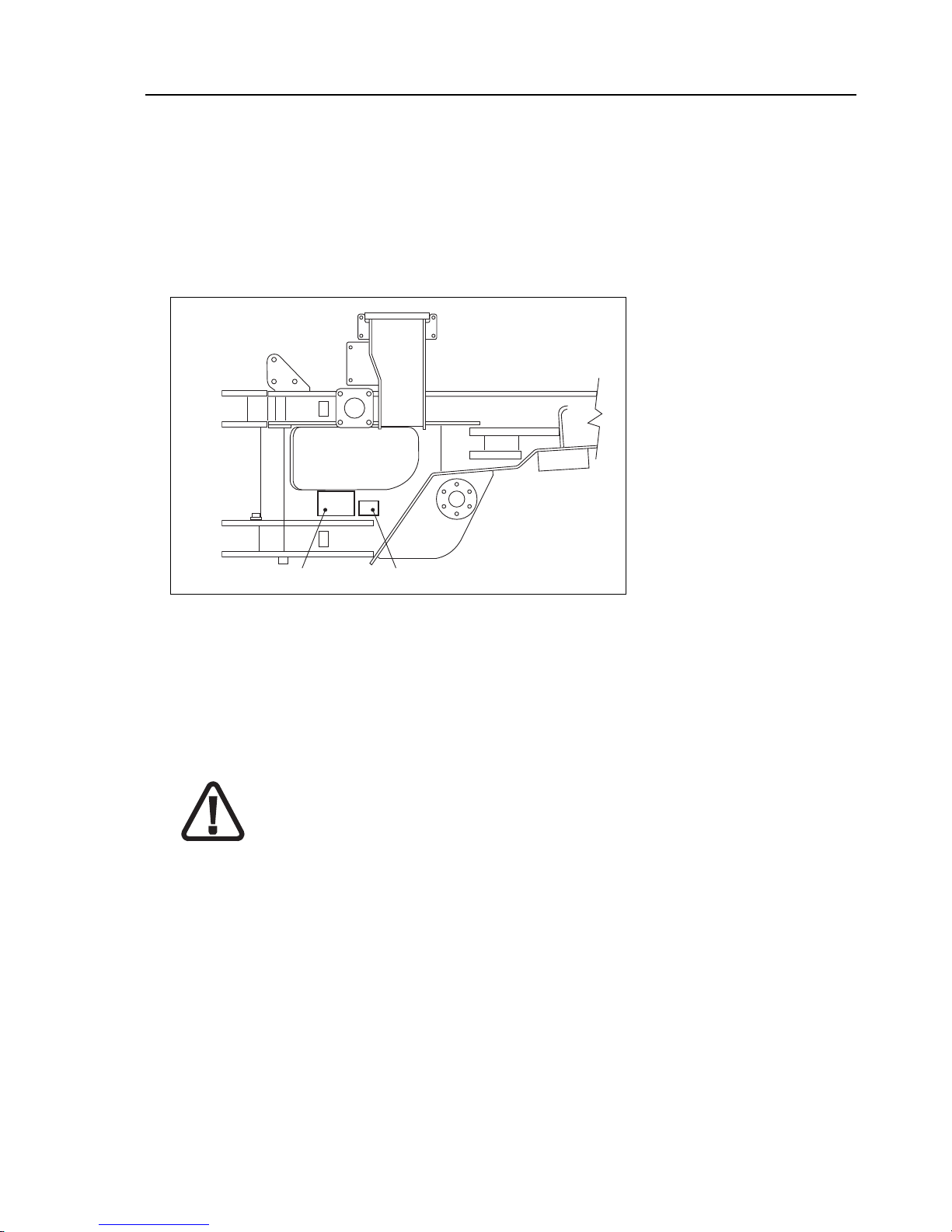
PRODUCT IDENTIFICATION NUMBER - PLATE LOCATION
Information regarding the machine model, code and chassis serial number is
found on the unit serial number plate on the rear right of the front frame. The
machine model and serial number should always be referenced in any
correspondence with your dealer or factory.
While reading this manual you will notice references to controls and
equipment which may not be found on all machines. It is important that you
know your machine and its equipment and how to operate it properly.
There is a dealer serving every part of the world where these products are
sold. Your dealer is ready to provide you with any additional information
needed and should be consulted for additional publications for this machine.
When carrying out repairs, alterations or fitting attachments, it is important
that only genuine spare parts are used to ensure the operating safety of the
machine is not impaired.
It is only by using genuine parts that the technical requirements stipulated by
the manufacturer can be maintained.
If a General Operating Approval is issued for this machine, it may be
considered null and void if non-genuine parts are used.
WARNING
SPARE PARTS
Serial Plate Location
CE Identification

Introduction
1-4
THEFT DETERRENT PRACTICES
General
The owner/operator should take the following precautions to discourage theft,
to aid in the recovery in the event that the machine is stolen, or to reduce
vandalism.
Actions to Discourage Theft and Vandalism
Remove all keys any time the machine is left unattended.
At night lock all doors and attach, secure or lock all anti-vandalism and
anti-theft devices on the machine.
Immobilize the machine by removing a critical electrical or starting system
device.
Upon receipt of a machine, record the machine serial number and the serial
numbers of all major components and attachments. Keep this list up to date
and filed in a safe location for fast retrieval.
Place a decal or notice on the machine that all serial numbers are recorded.
Discourage the thief! Inspect the gates and fences of the machinery
storage yard or construction site. Keep machines in well-lit areas and ask the
local law enforcement authorities to make frequent checks around the storage
yard or work site.
Establish liaison with neighbours and ask them to watch equipment left at job
sites and to report any suspicious activities to the local law enforcement
authorities.
Make frequent inventories of machines to promptly detect losses or
vandalism.
Actions to Aid in Recovery of Stolen Machines
In the event of theft, immediately notify the law enforcement authorities having
jurisdiction. Provide the investigating officer with name, type of equipment,
chassis and serial numbers of major attachments and components. It is
helpful to show the investigating officer an operations manual, photographs,
and advertising, to familiarize him with the appearance of the machine.
Report the theft to the insurance company. Provide the model and all serial
numbers.
Report the model and serial numbers of the stolen machine to a dealer
handling the respective line of equipment. Request that the dealer forward this
same information to the equipment manufacturer.

Safety
2-1
2 - Safety

Safety
2-2
This Page is Intentionally Left Blank
Safety
2-3
SAFETY
The machine should be properly operated and maintained to keep it
in a safe, efficient operating condition. Be sure that all controls are
free of mud, grease, or other matter that might cause slips hazardous
to the operator, serviceman, or other personnel or equipment. Report
all malfunctions to those responsible for maintenance, and, do not
operate the equipment until corrected. Normal service or
maintenance performed as required can prevent unexpected and
unnecessary downtime.
This operations manual describes general inspections, servicing and
operation with the normal safety precautions required for normal
servicing and operating conditions. It is not a guide however, for other
than normal conditions or situations, and therefore, servicemen and
operators must be safety conscious and alert to recognize potential
servicing or operating safety hazards at all times, and take, necessary
precautions to assure safe servicing and operation of the machine.
These machines use a solution of high purity urea (AdBlue) in
the def tank. Avoid prolonged or repeated contact with skin.
After handling, always wash hands thoroughly with soap and
water. In case of contact with eyes, rinse immediately with water.
If large quantities are ingested or irritation persists seek medical
attention immediately.
These machines are equipped with cylinders containing compressed nitrogen gas. Transportation of these machines by any
method may require a special permit from the appropriate
authority of the country involved. Consult your dealer for
details.
All information, illustrations and specifications contained in this
publication are based on the latest product information available at
the time of publication. The right is reserved to make changes at any
time without notice.
Continuing improvement and advancement of the design may cause
changes to your machine which may not be included in this
publication. Each publication is reviewed and revised, as required, to
update and include these changes in later editions.
This operations manual contains lubrication and routine servicing
instructions, most of which can be performed in the field.
Maintenance manuals containing repair/ rebuild procedures can be
obtained from your dealer.
WAR NING
CAUTION

Safety
2-4
SAFETY
General
• Read this operations manual and learn the operating
characteristics and limitations of the machine. Know what
operating clearances the machine requires.
• Read and understand all the safety signs prior to operation.
• If the safety signs are obstructed by dirt or debris, clean them
using mild soap and water prior to operation.
• If the safety signs are damaged or illegible, replace them
immediately, prior to operation.
• Read the AEM Safety Manual and follow the recommended
safety precautions.
• Know clearances of all side and overhead obstructions such as
wires, bridges, etc., for operating safely.
• Be especially aware of overhead power lines.
• Always know all traffic rules, signs, flags and hand signals used
on the job and know who has the responsibility for signalling.
• Be aware of operating hazards that weather changes can create
on the job. Know proper procedures to follow when a severe rain
or electrical storm strikes.
• Never attempt to operate or work on a machine when not feeling
physically fit.
• Know what safety equipment is required and use it. Such
equipment may be: Hard hat, safety glasses, reflector type vests,
respirators and ear plugs.
• Never wear loose clothing, rings, watches, heavy gloves etc., that
might catch levers and controls and cause loss of control.
• Keep hands and controls free from water, grease and mud to
assure nonslip control.
• Handle fuels and lubricants carefully and clean up spills to avoid
fire and slipping hazards.
• Clean any mud, grease or oil from controls, handrails, ladders
and decks. Lash necessary tools securely and remove all loose
items before operating the machine. Never rush. Walk, do not
run.
• Never carry more than one passenger and only in the passenger
seat.
SAFETY
MANUAL
1767
1768
1769
1782
Safety
2-5
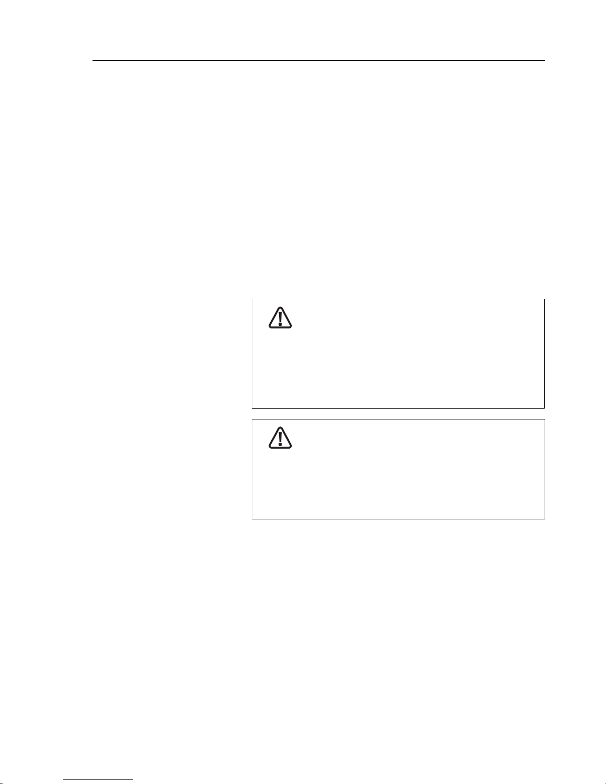
CAUTION
The protection offered by the roll over and falling object
protective structure may be impaired if it has been subjected
to any modification or damage. Unauthorized modification will
void certification.
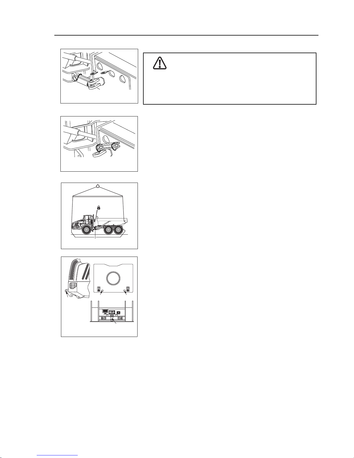
Articulation and Oscillation Lock
• Always connect the steering and oscillation lock bar before
working in the articulation area, before lifting the machine and
during transportation of this machine by trailer/vessel.
• Always disconnect the steering and oscillation lock bar and
secure in the 'Stowed' position before operating the machine. The
machine would not be free to steer otherwise.
Machine Lifting Precautions
• Prior to lifting, the machine should be parked on a level surface,
wheels blocked, steering and oscillation lock bars connected.
• The machine should be lifted using a spreader bar if possible. Lift
using FOUR slings from the lifting points provided at the bumper
end of the front chassis and at the rear of the body.
NOTICE: Be aware that this machine is free to oscillate if not lifted
correctly. If in any doubt contact your dealer for further information.
Machine Tie Down Precautions
• The machine should be secured at the tie down points located at
the bumper end of the front chassis, the front face of the trailer
chassis and the tow pin at the rear of the trailer chassis.
MOT00361
Articulation and Oscillation
Lock - ‘Locked Position’
MOT00362
Articulation and Oscillation
Lock - ‘Stowed Position’
TIE DOWN POINTS
LIFTING POINTS
Machine Lifting Instructions
2232
CENTRE
FRONT
REAR
Machine Tie Down Instructions
2161
Safety
2-6
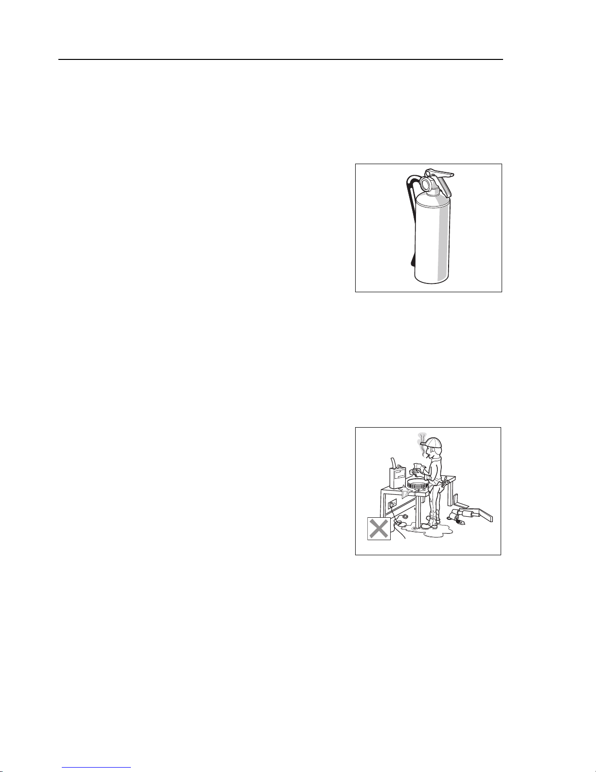
Preventing Fire Hazards
General Fire Precautions
• Make sure the machine has a fire extinguisher and that it is
accessible and fully charged. (Not furnished with the machine).
• Never use an open flame as a light anywhere on, or around, the
machine.
• Clean all dirt, oil, grease and other fluids from systems and
components to minimize fire hazards and aid in spotting loose or
leaking lines, fittings etc.
• Check the engine compartment for rubbish, oily rags or other
debris that could cause fires before starting the engine.
• Don’t let greasy, oily rags or similar hazards accumulate in the
cab.
• If the machine has been operated with an under inflated tyre,
make sure that the tyre has cooled sufficiently before parking and
leaving the machine unattended.
Flammable Fluid Precautions
• Don’t use diesel fuel or other flammable fluids for cleaning
purposes. Use approved, nonflammable solvents.
• Make sure all fluid system caps, drain cocks, valves, fittings, lines,
etc., are secure and leak free.
• Never use an open flame (match, lighter etc.) when checking fuel,
lubricant, coolant and battery fluid levels, or when checking for
fluid leaks. Use a flashlight or other safe lighting only.
• Shut off the engine and use extra caution if the engine is hot
when refuelling. Ground the hose spout to prevent sparks when
the spout touches the fuel tank filler tube.
• Never smoke while checking or adding fuel or other fluids or
handling fluid containers and lines.
• Use care and do not stand downwind when adding fuel or other
flammable fluids to tanks and reservoirs to avoid fluids being
blown or splashed onto clothing.
• Close fuel tank shut-off valves, if used, before servicing the fuel
system.
• When preparing machines or components for storage, seal and
tape all openings and close containers tightly to seal in all volatile
inhibitor fluids and compounds used.
1789
FUEL
1770
 Loading...