

Terex Gyro 4020, Gyro 4518 Service Manual
INDEX
Handler with telescopic boom
Gyro 4020 (From serial n. 12888)
Gyro 4518 (From serial n. 12508)
SERVICE MANUAL
Code 57.4402.8200 - 1
st
Edition 03/2007
English
Edition
Document 57.4402.8200 - 1
st
Edition 03/2007
INDEX
GYRO 4020 - 4518
Intentionally blank page
2

Document 57.4402.8200 - 1
st
Edition 03/2007
INDEX
3
GYRO 4020 - 4518
SERVICE MANUAL
Code 57.4402.8200 - 1
st
Edition 03/2007
Number: ....................................
Consigned to: ................................................................................................................................
DECLARATION
I, the undersigned..........................................................................................................................
declare I have received the Service Manual for TEREX handlers of the Gyro 4020 - 4518
series.
Copies consigned: n° ...... on paper
n° ......
on CD-Rom
The undersigned is obliged to use the manual in their workshop, without disclosing the information in the same in any way, to unauthorised workshops and third parties in general, and not to
photocopy or reproduce this manual or parts of the same in any way without the prior written
authorisation of TEREXLIFT to do so.
If business relations between the undersigned and TEREXLIFT should come to an end, the
undersigned is obliged to return the copies received without charges for TEREXLIFT.
Yours sincerely
Date ............................
For acceptance
The consignee Company stamp
and signature of the Legal representative
........................................... ...........................................
Copy to return stamped and signed for acceptance by the
Legal representative of the company receiving the copies of the manual.


Document 57.4402.8200 - 1
st
Edition 03/2007
INDEX
SERVICE MANUAL
Code 57.4402.8200 - 1
st
Edition 03/2007
Number: ....................................
Consigned to: ................................................................................................................................
DECLARATION
I, the undersigned..........................................................................................................................
declare I have received the Service Manual for TEREX handlers of the Gyro 4020 - 4518
series.
Copies consigned: n° ...... on paper
n° ......
on CD-Rom
The undersigned is obliged to use the manual in their workshop, without disclosing the information in the same in any way, to unauthorised workshops and third parties in general, and not to
photocopy or reproduce this manual or parts of the same in any way without the prior written
authorisation of TEREXLIFT to do so.
If business relations between the undersigned and TEREXLIFT should come to an end, the
undersigned is obliged to return the copies received without charges for TEREXLIFT.
Yours sincerely
Date ............................
For acceptance
The consignee Company stamp
and signature of the Legal representative
........................................... ...........................................
3
GYRO 4020 - 4518

Document 57.4402.8200 - 1
st
Edition 03/2007
INDEX
Revision Revised pages Notes Issued by
No. Date
1 03-2007 Publication
2
3
4
5
6
7
8
9
10
11
12
13
14
15
16
17
18
19
20
21
22
23
24
25
26
27
28
29
30
31
32
33
34
35
36
37
38
39
40
GYRO 4020 - 4518
LIST OF REVISED PAGES
4

Document 57.4402.8200 - 1
st
Edition 03/2007
INDEX
MANUAL CONTENTS
INTRODUCTION
Sect. 1 SAFETY RULES
Sect. 2 TECHNICAL SPECIFICATIONS
Sect. 3 SCHEDULED MAINTENANCE INSPECTIONS
Sect. 4 SCHEDULED MAINTENANCE PROCEDURES
Sect. 5 TROUBLESHOOTING
Sect. 6 SCHEMES
Sect. 7 REPAIR PROCEDURES
5
GYRO 4020 - 4518
GENERAL INDEX

Document 57.4402.8200 - 1
st
Edition 03/2007
INDEX
Machine denomination Literature valid up to serial number
Gyro 4020 12888
Gyro 4518 12508
TELELIFT 4013
SERIAL NUMBER IDENTIFICATION
6

Document 57.4402.8200 - 1
st
Edition 03/2007
INDEX
i
GYRO 4020 - 4518
INTRODUCTION
INTRODUCTION
Important
Read, understand and obey the safety rules and operating
instructions in the Gyro 4020 and Gyro 4518 Operator's
Handbook before attempting any maintenance or repair
procedure.
This manual provides the machine owner and user with
detailed information on the scheduled maintenance. It also
provided qualied service technicians with infromation on
troubleshooting and repair procedures.
Basic mechanical, hydraulic and electrical skills are
required to perform most procedures. However, several
procedures require specialized skills, as well as specic
tools and equipment.
In these instances, we strongly recommend letting service
and repair the machine at an authorized TEREXLIFT
service center.
Technical Publications
No part of this publication may be reproduced, stored in a
retrieval system or transmitted in any form or by any means
without prior written permission from TEREXLIFT srl.
In pursuing a policy of constant quality improvement,
TEREXLIFT srl reserves the right to make changes at any
time and without undertaking to give prior notice; therefore,
also this publication may be subject to modications.
Contact Us
http://www.terexlift.com
e-mail: info@terexlift.it
© Copyright 2007 TEREXLIFT srl - All rights reserved

Document 57.4402.8200 - 1
st
Edition 03/2007
INDEX
GYRO 4020 - 4518
INTRODUCTION
ii
DESCRIPTION OF THE MACHINE OPERATION
The oil-pressure system of this machine consists of two
macro sections, namely turntable and undercarriage,
corresponding to the machine's main parts. From an oilpressure point of view, these two sections are connected
with one another by the 13-way hydraulic rotary joint
(9).
The source of mechanical energy of this machine is
a Deutz turbo-compressed diesel engine (1), model
BF4M2012, which supplies 74.9 kW at 2300 rev/min
and with a max torque of 390 Nm at 1500 rev/min.
On the ywheel side of the engine, and connected to
this engine by a Technodrive coupler with elastic joint
and with a 1-to-1 ratio, there is a Linde closed-loop
pump for hydrostatic drives, model HPV 75-02RE112V
(2) with electroproportional adjustment valves.
The max displacement of this swashplate pump is 75
cm3 and the max calibration pressure is 445 bar.
This pump is used to supply hydraulic power under form
of pressure and ow rate which is then used for moving
the machine.
This pump is used to supply hydraulic power under form
of pressure and ow rate which is then used for moving
the machine.
On the through-shaft of such drive pump there is a
Bosch-Rexroth variable displacement piston pump
with swashplate suitable for open lopp circuits, model
A10VO45DFR (3), equipped with ow and pressure
control valve.
The displacement of this pump is 45 cm3. The function of
this pump, through the “load sensing” priority valve (6) is
to provide hydraulic power, under form of pressure and
ow rate to the steering cylinder of the machine (priority
side of the valve) and to the telescopic boom and slewing
turntable circuits (secondary side of the valve).
This "load sensing" pump is adjusted through an
adequate piloting line which provides the pump a
pressure signal corresponding to the max load of all the
users fed by this pump.
Between pump (3) and priority valve (6), a one-way valve
(5) is placed to avoid that oil at pressure, produced by
the power-driven emergency pump (48), may escape
from pump (3) when this is stopped.
The assembly of the two pumps involves they have
a rotation velocity equal to the speed of the diesel
engine.
A third Casappa xed displacement gear pump suitable
for open loop circuits (4) with a displacement of 25 cm3,
is installed on the PTO of the engine located on the
distribution side.
This pump feeds the servo-assisted braking system
(35) and the hydraulic motor (42) of the heat exchanger
fan (43) used to cool down the diesel engine and the
hydraulic circuit.

Document 57.4402.8200 - 1
st
Edition 03/2007
INDEX
iii
GYRO 4020 - 4518
INTRODUCTION
The circuit of pump (4) is protected by a pressure relief
valve 33) calibrated to 160 bar.
The suction lines of the open-loop pumps (3-4) and the
power-driven emergency pump (48) are not protected by
lters and are conveyed to a single port on the hydraulic
uid tank (32).
Between this port and the suction lines of the aforesaid
pumps, there is a gate valve (31) that allows to perform
important maintenance interventions on the oil-pressure
circuit of the machine without emptying the oil tank. This
tank has a capacity of 230 litres.
On the contrary, the drive pump (2) is protected by a
special lter (45), placed on the discharge line of pumps
(3-4). This lter puries the oil from the open circuits of
the machine (boom-turntable control circuit and service
and parking brake feeding circuit) and allows to have
an additional oil port for the drive suction line with a
minimum pressure of 0.5 bar.
This construction feature of the lter guarantees
signicant advantages in terms of absence of cavitation
in the drive suction line, especially when the machine is
started from cold.
The one-way valve (34) set to 1.5 bar protects the
pump housing against high pressures and guarantees
a certain circulation of the drain oil to the hydrostatic
motor reducing, in this way, the temperature.
From port “X” of the drive pump (2) low-pressure oil
is taken (25-30 bar). This oil is rst conveyed to the
undercarriage through port 11 of the hydraulic rotary
joint (9), and then used for the two-speed mechanical
gearbox circuit (51), for the adjustment of the hydrostatic
drive motor (50) and for the differential anti-slip circuit
through the mechanism placed inside the front axle
(57).
The hydraulic energy produced by the drive pump (2)
and conveyed to the undercarriage through ports n.1
and n.2 of the hydraulic rotary joint (9), is converted into
mechanical power by a closed-loop hydrostatic motor,
model Linde HMV 75-02E112V (50) equipped with an
electroproportional adjustment valve and with a ush
valve for reducing the max temperatures inside the
drive circuit.
In addition to the high-pressure connections with pump
(2) throughj ports n. 1 and n. 2 of the hydraulic rotary
joint (9), the motor (50) is hydraulically connected to the
turntable through port n.12 of the aforesaid joint from
which it receives the ow from the drain circuit of the
drive pump (2), through port n. 7, to which it conveys
all the drain ow, and through port n. 11, from which it
takes the low pressure needed for its adjustment.
The electroproportional valves of pump (2) and motor
(50) are controlled by a dedicated electronic control
unit (Linde) which is connected to the remaining control
devices of the machine through the digital network.

Document 57.4402.8200 - 1
st
Edition 03/2007
INDEX
GYRO 4020 - 4518
INTRODUCTION
iv
The motor is anged to a two-speed mechanical
gearbox, model 357 (51) manufactured by Dana.
Speeds are engaged by a special oil-dynamic cylinder
(52) located inside the gearbox, while the selection of
the rst and second speed is controlled by a 4-way/3-
position solenoid valve (53) of the on/off type.
The mechanical torque at the gearbox output is
transmitted to the front axle (57) and the rear axle (58),
both model 212HY manufactured by Dana, through
Cardan shafts.
The hydraulic drive (7) of “load sensing” type with a
displacement of 315 cm3, receives oil from the priority
valve (6) in relation to the “load sensing” signal sent by
the hydraulic drive and connected to such valve with
function of pilot signal. In this way, the input ow to the
hydraulic drive will be exactly the one needed for the
instantaneous steering functions; any excess ow of the
valve will be available for the functions of the telescopic
boom asn other auxiliary functions.
The steering circuit is protected against input
overpressures by a pressure reducing valve set to
140 bar. On the two delivery lines, there are other two
reducing valves with anti-shock function set to 200
bar. The scope of these two valves is limiting possible
shocks on the steering wheel due to overstress on the
steering cylinders. The three pressure reducing valves
are installed in the hydraulic drive (7) and cannot be
regulated from the outside.
The steering circuit is completed by the front steering
cylinder (55), the rear steering cylinder (56) (these
cylinders being integral part of the front axle (57) and
the rear axle (58) respectively) and by a 4-way/3position solenoid valve (54) for the selection of the three
different steer modes (rear wheels straight, co-ordinate
front/rear steering and independent front/rear steering).
When the solenoid valve (54) is not energised, the front
steering cylinder is fed by the hydraulic drive and the
rear cylinder is blocked. When one magnet or the other
of the solenoid valve (54) is energised, the chambers of
the cylinders are connected in a different manner thus
causing the desired effect on the steering mode.
The connection of the steering circuit between the
section integral of the turntable and the one integral of
the undercarriage is done through ports n.8 and n. 9 of
the hydraulic rotary joint (9).
The Bucher/Tecnord electro-proportional distributor
(8), with 5 modular sections, receives oil from the
secondary line of the priority valve (6) and feeds all of
the movements of the telescopic boom and the turntable
and provides an oil ow to the auxiliary lines for the
secondary functions such as turntable lock, outriggers
and frame levelling.
This main valve consists of an input head with 3-way
pressure compensator used as a ow regulator for the
user which works at max load (load sensing), and as a

Document 57.4402.8200 - 1
st
Edition 03/2007
INDEX
v
GYRO 4020 - 4518
INTRODUCTION
discharge valve when the pump ow is not used for the
boom movements, and of 5 modules.
Four of these modules control specic functions of the
telescopic boom (lifting/lowering, attachment holding
frame rotation, extension/retraction, attachment lock/
unlock) and the fth module controls the rotation of the
turntable of the machine.
In the head there is a pressure relief valve set to 300
bar which, acting on the line of the “load sensing” signal,
limits the maximum pressure at the inlet of the main
valve through such 3-way compensator.
On the main inlet head of the main valve, there is the pilot
line head which includes an inlet safety lter, a pressure
relief valve acting on the pilot line, and a safety solenoid
valve which, when de-excited, discharges the input pilot
pressure, thus preventing the main valve from working.
This solenoid valve is used as a “dead man” control and
is activated by the relevant button on the joysticks in the
driving cab.
The pilot head delivers oil at pressure to the 5 pilot
modules of the main valve. These modules operate the
relevant main sliders in relation to the command signal
they receive from the joysticks via the control unit.
Module 1 of the main valve controls the telescopic
boom lifting cylinder (12). This cylinder has one singleacting compensation valve (13) with safety function.
The control module of element 2 of the main valve is
the electro-proportional type with electrical feed-back
and integrated electronics. The 1,5-lt. accumulator
prelled at 35 bar (14) and located on the line of the
differential chamber of the lifting cylinder (12), allows
for damping the boom swings when the same boom is
moved down.
Module 2 of the main valve controls the boom telescopes
extension cylinder (15). This cylinder is equipped with
a double-acting compensation valve (16) with safety
function. The control module of this element of the main
valve is the electro-proportional type with electrical
feed-back and integrated electronics.
Module 3 of the main valve controls the cylinder
operating the attachment holding plate of the telescopic
boom (17). This cylinder is equipped with a doubleacting compensation valve (18) with safety function.
Paralleled to this cylinder we nd the fork levelling
cylinder (19) (or balancing cylinder) equipped with a
special double-acting compensation valve (20). Inside
this valve, the one-way valves are installed in a reverse
manner with respect to the normal position to avoid
the pressurisation of the cylinder when the rotation
command of the attachment holding plate is operated.
Again inside this valve, there are other two one-way
valves set to 5 bar with anti-cavitation function (21).
These valves are used to deliver oil, sucked from the
low pressure line coming from the pressure relief valve
(11), to the fork levelling compensation circuit, when such

Document 57.4402.8200 - 1
st
Edition 03/2007
INDEX
GYRO 4020 - 4518
INTRODUCTION
vi
circuit cannot do it alone.
The control module of element 3 of the main valve is the
electro-proportional type with electrical feed-back and
integrated electronics.
On the two control lines of the cylinder (17), and integral
to module 3, there are two pressure relief valves set to
320 bar which protect the automatic levelling system of
the forks when the boom is moved up and down and in
case of overload on the attachment holding plate (ex.
use of the bucket).
Module 4 of the main valve controls the attachment
locking cylinder (23). This cylinder has a double oneway valve with hydraulic release, acting as safety valve
(24). The pilot module of element n. 4 of the main valve
is the electroproportional type with integrated electric
and electronic feedback.
On one of the two hydraulic control lines of this section
of the main valve, there is a 3-way/2-position electric
divider with on/off control (22).
When this divider is not energised, the oil at pressure
coming from the module of the main valve, is sent to
the attachment locking cylinder. On the contrary, when
the divider (22) is energised, the oil at pressure from
element n.4 of the main valve (8), is made available for
the auxiliary feeding line of the turntable lock/unlock
function and, through port n. 3 of the hydraulic rotary
joint (9), for the operation of the outriggers and the
frame levelling.
On the feeding lines of this cylinder and close to the
terminal part of the end trunk, there are two quick-t
connectors (25) for the connection of the hydraulic lines
of any optional equipment needing a hydraulic power
for their operation (e.g. hydraulic winch and jib, mixing
bucket, etc.).
Module n. 5 of the main valve controls the hydraulic
slewing motor of the turntable (26), equipped with brake
with internal mechanical block and external hydraulic
release. The mechanical torque produced by this motor
is transmitted to the turntable through an epicyclic
reduction gear with two stages and a slewring with
internal toothing.
The feeding line of this motor is equipped with a doubleacting compensation valve (27), used also as safety
and anti-cavitation valve.
The pilot module of this element of the main valve is
of electroproportional type with integrated electric and
electronic feedback.
Inside this module of the main valve, there is a two-way
pressure compensator which keeps the proportionality
of the slewing control of the turntable as the loads on this
table and the pressure entering the main valve modules
change. The pressure of the main valve is adjusted by
the three-way compensator placed on the inlet head.
The main valve (8) is equipped with a pilot line of the
“load sensing” type which, through the exchange valve
(10), is connected to the priority valve (6), which, at

Document 57.4402.8200 - 1
st
Edition 03/2007
INDEX
vii
GYRO 4020 - 4518
INTRODUCTION
its turn, receives an analog pressure signal from the
hydraulic drive (7). The exchange valve (10) is then
connected to the "load sensing" port of pump (3), thus
guaranteeing the adaptation of the pump adjustment to
the maximum load on the various users served by this
pump under any conditions.
The pressure relief valve (11) calibrated to 30 bar is
placed upstream of the pressure inlet port of the main
valve (8). This valve is used to deliver low-pressure oil
(30 bar) to the anti-cavitation circuits of automatic fork
levelling system and to feed the pilot line of the same
main valve (8).
The block cylinder of the slewing turntable (28) is
equipped with a double one-way valve (29) with hydraulic
release, acting as safety valve, and is controlled by the
4-way/3-position solenoid valve of the on/off type (30).
As already mentioned, the turntable lock/unlock is
possible through the simultaneous energisation of
module n.4 of the main valve (8), the electric divider
(22) and the solenoid valve (30).
The SAFIM S6 servo-assisted braking system with pedal
(35) receives oil from the pump (4) and uses this oil to
pressurise 3 hydraulic accumulators (36-37) connected
to the same system.
The oil at pressure contained in these accumulator is
then used to operate the service brakes of the two axles
(57-58) and to release the parking brake located inside
the rear axle (58).
The ll valve inside the braking system takes the ow
from the feeding line so the pressure on the line of the
accumulators reaches the calibration value of the cutout
valve set to 140 bar. When this pressure is reached, the
valve gradually releases all the ow to line B for other
uses.
The brake pedal located in the driving cab, which is an
integral part of the braking system S6, is connected to
two proportional sliders which control the two separated
lines of the service brake, one for each axle.
Such lines connect the part of circuit in the turntable with
the one in the undercarriage through ports n. 5 and n. 6
of the hydraulic rotary joint (9). In relation to the stroke
of these sliders, a gradual communication between
the feeding line, connected to two accumulators (36)
which, at their turn, are connected to ports R1 and R2
(the accumulators have 0.5-lt. capacity and 50 bar ll
pressure), and the service brake lines is established so
the ow is distributed to such lines and the discharge
line increasing, in this way, the pressure (and as a result
the braking force) on the lines of the service brakes.
When the sliders are in the rest position, the lines of the
service brakes are connected to the discharge.
The pressure switch (38) set to 2-10 bar, paralleled to on
of the two lines of the service brake, sends an electrical
signal when this brake is engaged.

Document 57.4402.8200 - 1
st
Edition 03/2007
INDEX
GYRO 4020 - 4518
INTRODUCTION
viii
The pressure switch (39) set to 70 bar and connected
to port F, sends an electrical warning signal when the
pressure inside the feeding circuit of the brake lines is
too low to guarantee the minimum braking efciency.
The accumulator (37) with 0.5-lt. capacity and 50 bar
ll pressure is connected to port R of system S6 and is
used to unlock the parking brake of the rear axle (58).
The connection of the part of this circuit placed in the
turntable to the one of the undercarriage is done through
port n. 13 of the hydraulic rotary joint (9).
The command of the parking brake is controlled by
a special valve with lever control (40) located in the
driving cab. In relation to the position of the lever, the
release line of the parking brake is connected to the
pressure line (parking brake unlocked) or the discharge
line (parking brake locked).
The two pressure switches (41) set to 10-20 bar send
an electrical warning signal when the parking brake is
activated (brake locked).
The oil which is not used by the SAFIM S6 servo-assisted
braking system with pedal, is sent to the Casappa
hydraulic geared motor (42) with a displacement of 20
cm3, for the operation of the cooling fan of the heat
exchanger (43).
Inside the motor housing, there are an anti-cavitation
valve and a pressure relief valve with by-pass function
set to 140 bar, as well as a solenoid valve which, once
electrically energised, directly sends the oil entering to
the motor, to the drain.
The function of this solenoid valve, suitably controlled
by a thermostatic circuit, is to avoid an operation of the
cooling fan of the heat exchnager when the oil is cold.
This allows reaching the ideal working temperature of
the hydraulic oil faster.
The heat exchanger (43) is divided in two sectors; one
absorbs heat from the cooling circuit of the diesel engine
and the other absorbs heat from the hydraulic circuit of
the machine.
The ows of pumps (3-4) and the partial ow of the drain
circuit of the hydrostatic transmission are conveyed to
this second sector.
The oil cooled down by the heat exchanger is sent back
to tank (32).
A one-way valve (44) with an opening pressure of 5 bar
is installed parallel to heat exchanger (43) to protect the
same exchanger. In all the cases in which the pressure
drop in the exchanger exceeds 5 bar (starts from cold,
partial obstruction of the heat exchanger, etc.), valve
(44) opens so that a part of the ow to the exchanger
can be conveyed through this valve by reducing the
maximum pressure inside the exchanger (43).
On the drain line from the drive motor (50), passing
through port n.7 of the hydraulic rotary joint (9), there are
two one-way valves (46-47) with an opening pressure of
0.5 bar and 1.5 bar, respectively.

Document 57.4402.8200 - 1
st
Edition 03/2007
INDEX
ix
GYRO 4020 - 4518
INTRODUCTION
The function of these valves is to avoid a pressure of
the drain line of motor (50) above 1.5 bar which is the
admissible limit for the seals placed on the motor shaft.
This circuit allows for the partial passage through the
heat exchanger (43) of the ow from the pump drain
circuit (2) and the drive motor (50) to keep within the
pressure limits mentioned above. Any excess ow will
pass through valve (47) to directly reach the tank (32).
Ports n.4 and n.10 of the hydraulic rotary joint (9) are
used to connect some drain lines between undercarriage
and turntable. In particular, port n.10 is the one which
can guarantee the lowest counter-pressure values on
the drain, being directly connected to tank (32).
The motor-driven pump (48), supplied with power by the
battery, is used as emergency feeding pump in the event
of a failure of the primary control circuit of the telescopic
boom. Just downstream of the motor-driven pump (48)
there is a one-way valve (49) which avoids that oil at
pressure, produced by the main pump (3), may escape
through pump (48) when this is stopped.
The movements of the front outriggers are controlled
by four 4-way/3-position solenoid valves of the o/off
type, installed on the oil-pressure block (70). This block,
through port 3 of the hydraulic rotary joint (9), is fed
by the simultaneous operation of the 4th element of the
electro-proportional main valve (8) and of the electric
divider (22).
The solenoid valve n. 1 of block (70) controls the
cylinder (71) operating the front left stabilising foot. This
cylinder is equipped with a double-acting compensation
valve(72) used also as safety valve.
On the rod side of this cylinder, there is a pressure
gauge (73) calibrated to 50 bar which detects when the
outrigger is lowered to the ground.
The solenoid valve n. 2 of block(70) controls the
extension cylinder (74) of the front left outrigger. This
cylinder is equipped with a double one-way valve with
hydraulic release, acting as a safety valve (75).
The solenoid valve n. 3 of block (70) controls the
extension cylinder (76) of the front right outrigger.
This cylinder is equipped with a double one-way valve
with hydraulic release, acting as a safety valve (77).
The solenoid valve n. 4 of block (70) controls the
cylinder (78) operating the front right stabilising foot.
This cylinder is equipped with a double-acting
compensation valve (79) used also as safety valve.
On the rod side of this cylinder, there is a pressure
gauge (80) calibrated to 50 bar which detects when the
outrigger is lowered to the ground.
The movements of the rear outriggers are controlled by
four solenoid valves installed on the oil-pressure block
(81).
This block, through port 3 of the hydraulic rotary joint
(9), is fed by the simultaneous operation of the 4th
element of the electro-proportional main valve (8) and
of the electric divider (22).

Document 57.4402.8200 - 1
st
Edition 03/2007
INDEX
GYRO 4020 - 4518
INTRODUCTION
x
The solenoid valve n. 1 of block (81) controls the
cylinder (82) operating the rear left stabilising foot.
This cylinder is equipped with a double-acting
compensation valve (83) used also as safety valve.
On the rod side of this cylinder, there is a pressure
gauge (84) calibrated to 50 bar which detects when the
outrigger is lowered to the ground.
The solenoid valve n. 2 of block (81) controls the
extension cylinder (85) of the rear left outrigger.
This cylinder is equipped with a double one-way valve
with hydraulic release, acting as a safety valve (86).
The solenoid valve n. 3 of block (81) controls the
extension cylinder (87) of the rear right outrigger.
This cylinder is equipped with a double one-way valve
with hydraulic release, acting as a safety valve (88).
The solenoid valve n. 4 of block (81) controls the cylinder
(89) operating the rear right stabilising foot.
This cylinder is equipped with a double-acting
compensation valve (90) used also as safety valve.
On the rod side of this cylinder, there is a pressure
gauge (91) calibrated to 50 bar which detects when the
outrigger is lowered to the ground.
The differential anti-slip circuit is controlled by the 3way/2-position solenoid valve (69). When this valve
is not energised, the service brake control line of the
front axle (57), coming from the SAFIM braking system
(35) through port 5 of the hydraulic rotary joint (9), is
connected to the service brake ports of the front axle
(57). On the contrary, when valve (69) is energised, a
condition corresponding to the anti-slip control "ON", the
service brake ports of the front axle (57) are connected
to the 25-30bar low-pressure line and help the action of
the differential anti-slip system.
The oscillation of the front axle (57) is controlled by two
cylinders (60-63) equipped with block solenoid valves
(61-62). The movement of cylinders (60-63), and thus
the front axle oscillation (57), is only possible when
solenoid valves (61-62) are energised.
The frame levelling is controlled by a 4-way/3-position
ON/OFF solenoid valve (59) which feeds in a crossed
manner the cylinders (60-63).
This solenoid valve, through port 3 of the hydraulic rotary
joint (9), is activated by the simultaneous operation of
the 4th element of the electro-proportional main valve (8)
and of the electric divider (22).
The oscillation of the rear axle (58) is controlled by two
cylinders (65-68) equipped with block solenoid valves
(66-67). The movement of cylinders (65-68), and thus
the rear axle oscillation (58), is only possible when
solenoid valves (66-67) are energised.
The ow control valve (64) allows for the free passage
of the oil coming from the drive drain circuit during the
lling of the cylinders (65-68) (air venting) and avoids
pressure peaks in the circuit of such cylinders when high
oscillation speed conditions of the rear axle produce
potentially dangerous overpressures in the drive drain

Document 57.4402.8200 - 1
st
Edition 03/2007
INDEX
xi
GYRO 4020 - 4518
INTRODUCTION
circuit.
As already mentioned, the undercarriage levelling
function is possible through the simultaneous
energisation of the two spools of the solenoid valve (59)
and the spools of the solenoid valves (61-62-66-67).
Document 57.4402.8200 - 1
st
Edition 03/2007
INDEX
GYRO 4020 - 4518
INTRODUCTION
xii
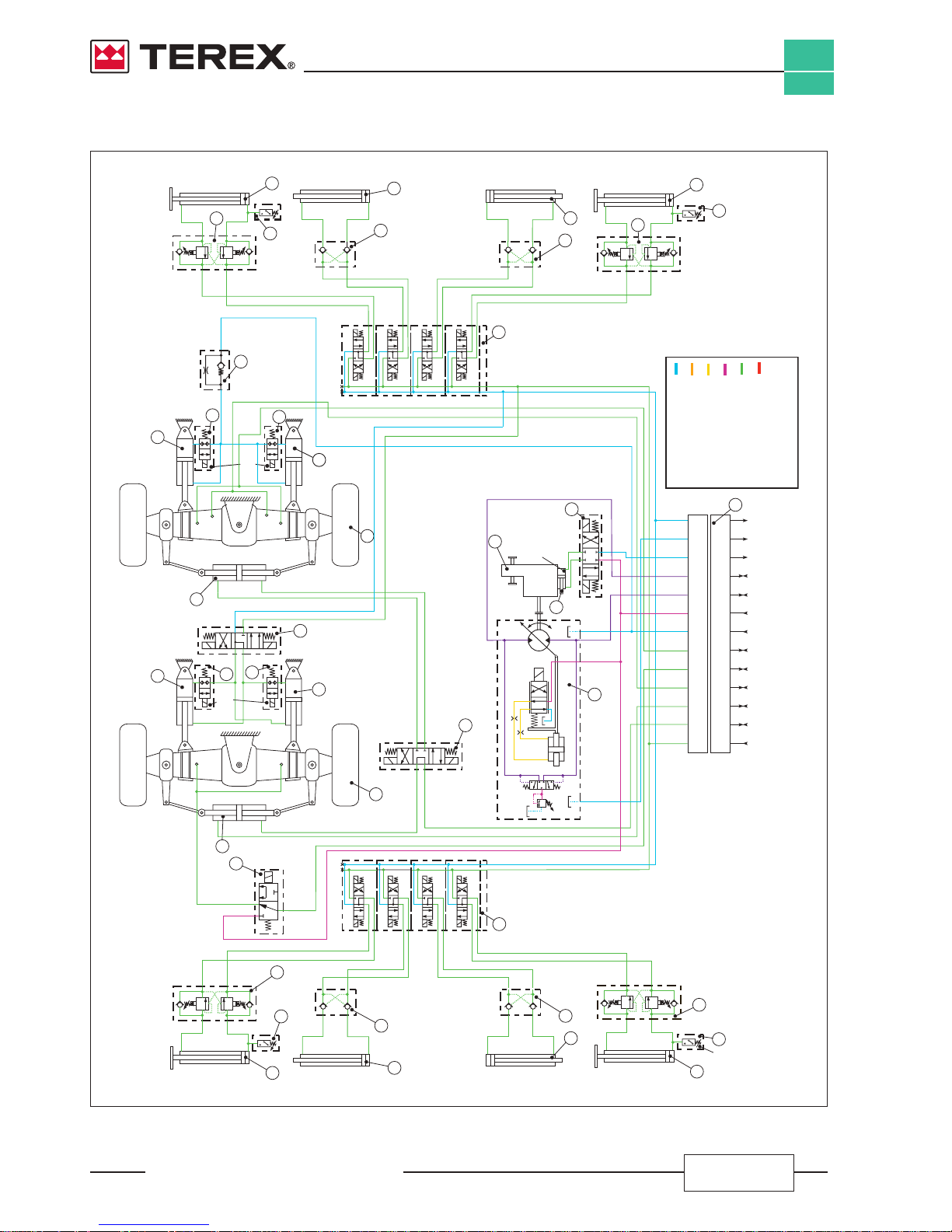
Gyro 4020 - 4518 carrier hydraulic scheme
71
72
78
79
57
68
55
64
59
63
6065
58
62
56
67
61
66
70
54
53
T
T
T
T
P
P
P
P
A
A
A
A
A
A
A
B
B
B
B
B
B
B
75
74
77
76
82
83
89
90
81
T
P
A
A
A
A
B
B
B
B
86
85
88
87
50
A
L
B
E
U
1
1 2
2
3
3
4
4
5
5
6
6
7
7
8
8
9
9
10
10
13
13
11
11
12
12
9
52
51
C
T
P
69
Double overcenter safety valve
piloting ratio: 11 1
cracking pressure: 200 350 bar
/
/
Front left outrigger
foot cylinder
Rear left outrigger
foot cylinder
Rear right outrigger
foot cylinder
Front right outrigger
foot cylinder
Front left outrigger
telescope cylinder
Rear left outrigger
telescope cylinder
Rear right outrigger
telescope cylinder
Front right outrigger
telescope cylinder
Hydraulically piloted
double check valve
piloting ratio: 41/
Hydraulically piloted
double check valve
piloting ratio: 41/
Hydraulically piloted
double check valve
piloting ratio: 41/
Rear outriggers
selector valves block
Front outriggers
selector valves block
Hydraulically piloted
double check valve
piloting ratio: 41/
84
91
73
80
Pressure
switch
activating
pressure
50 bar
Pressure
switch
activating
pressure
50 bar
Differential lock
selector valve
3 ways / 2 positions
Front axle
steering cylinder
Front axle levelling
cylinder (right)
Rear axle pivoting
cylinder (right)
Rear axle pivoting
cylinder (left)
Front axle levelling
cylinder (left)
Rear axle
steering cylinder
Front axle
Rear axle
Steering modes
selector valve
4 ways / 3 positions
Mechanical gear
speeds selector valve
4 ways / 3 positions
2 speeds mechanical gear
Mx
14 bar
Mechanical gear
speeds shifting
actuator
Chassis leveling
selector valve
4 ways / 3 positions
13 ways hydraulic rotating collector
Rear axle pivoting cylinders
control valve
orifice dia.: 0.5 mm
cracking pressure: 0.5 bar
Hydrostatic transmission motor
max displacement: 75 ccrev
/
Double overcenter safety valve
piloting ratio: 11 1
cracking pressure: 200 350 bar
/
/
Double overcenter safety valve
piloting ratio: 111
cracking pressure: 200 350 bar
/
/
Double overcenter safety valve
piloting ratio: 111
cracking pressure: 200 350 bar
/
/
HYDRAULIC CIRCUIT
COLORS LEGENDA
Boom teering, brakes, auxiliaries
and chassis levelling functions lines
/ s
Low pressure lines
Boom functions valve piloting lines
Boom teering, brakes, auxiliaries,
chassis levelling pump pressure lines
/ s
Boom teering, auxiliary pumps
suction lines
/ s
Tank lines
Pressure
switch
activating
pressure
50 bar
Rear axle pivoting
lockout valves
2 ways/2 positions
Front axle pivoting
lockout valves
2 ways/2 positions
Pressure
switch
activating
pressure
50 bar
Document 57.4402.8200 - 1
st
Edition 03/2007
INDEX
xiii
GYRO 4020 - 4518
INTRODUCTION
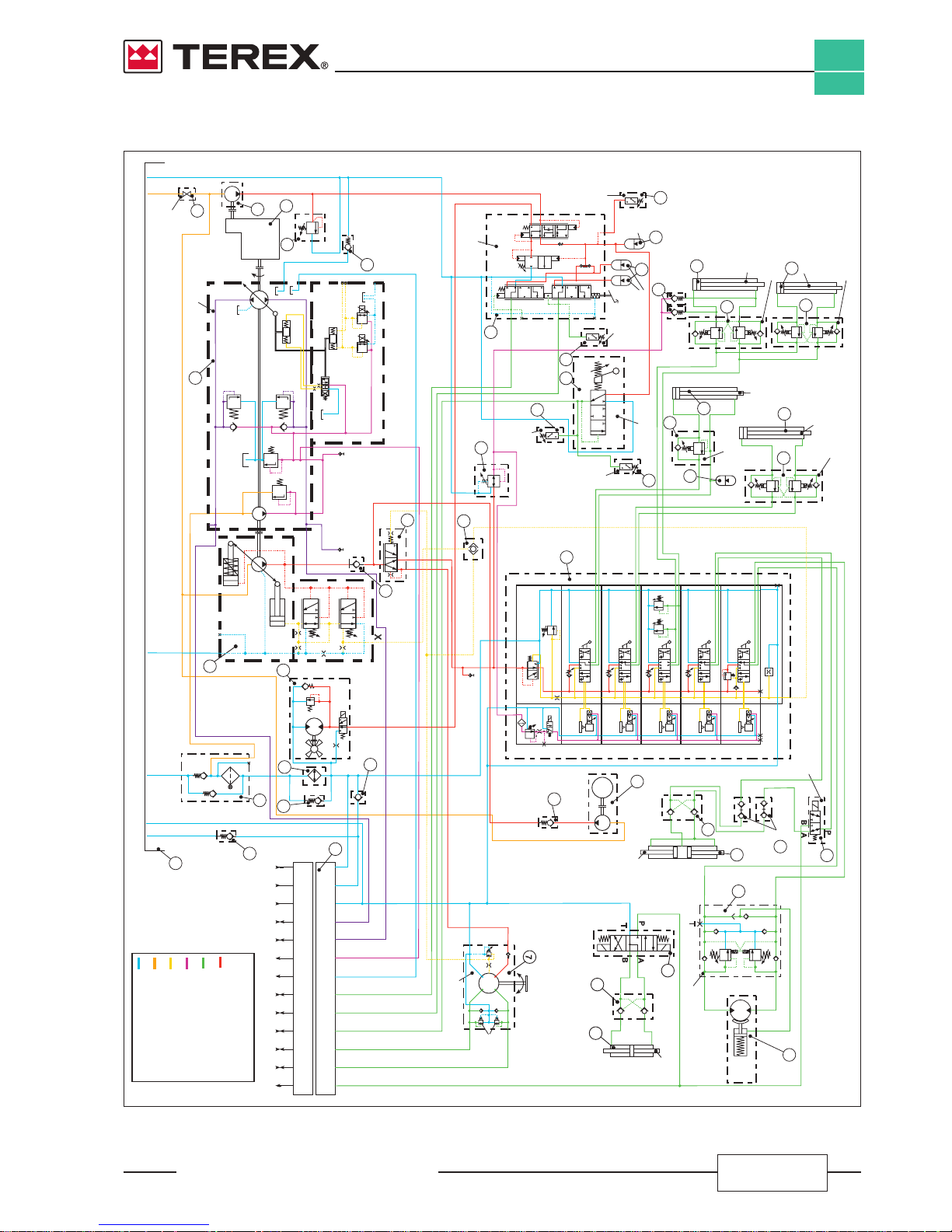
Gyro 4020 - 4518 turntable hydraulic scheme
32
44
47
42
28
29
7
30
24
23
25
4
2
31
1
34
11
10
8
40
35
39
19
18
15
16
14
12
13
17
20
21
41
36
37
41
38
6
5
3
M
V1
V2
C1
C2
C3
T
P
B A
T
P
A
B
CF
EF
LS
1
1
2
2
3
3
4
4
5
5
6
6
7
7
8
8
9
9
10
10
13
13
11
11
12
12
27
22
26
M
46
43
9
45
48
49
33
E
E
E
320 bar
320 bar
300 bar
140 bar
200 bar
Unlocking
pressure
15/50 bar
1
1
0
0
2
2
E
1
0
2
1
0
2
E
1
0
2
T2
T1
LS
A
A
A
A
A
B
B
B
B
B
P
P
T
LS
Pp
Tp
Tp
FLT
Pp
RPM
G1
Ev13
Pv1
Pv2
Pv3
Pv5
Pv4
N
R
F
P
B
N’
R1
T1
T1’
T2’
T2
R2
capacity:
0.5 Litri
precharge
pressure
50 bar
capacity:
0.5 Litri
precharge
pressure
50 bar
Pressure
switch
activating
pressure
70 bar
Pressure
switch
activating
pressure
2-10 bar
Pressure
switch
activating
pressure
10 bar-20
Pressure
switch
activating
pressure
10 bar-20
Hydraulically powered
service/emergency brakes
pedal pump
R
T
N
140 bar
30 bar
Parking brake handle
selector valve
P
U
M
p
M
s
S
B
A
F
X
Z
T
Y
L
Hydrostatic transmission pump
max displacement 75 cc/rev
25 bar
19 bar
445 bar
445 bar
TP
3
TP
2
TP
1
Hydrostatic transmission
boost pressure test port
Pressure reducing valve
setting pressure: 30 bar
Shuttle
valve
Priority
valve
Hydrostatic transmission
high pressure test port
0.9
0.9
My
Mz
Boom functions pump
withpressure/flow control
max displacement: 45 cc/rev
S
L
1
L
B
X
Anticavitation valves
cracking pressure
5 bar
Forks levelling
slave cylinder
Boom telescoping cylinder
Forks tilt cylinder
Boom lift
cylinder
Double overcenter safety valve
piloting ratio: 41
cracking pressure: 350 bar
/
Double overcenter safety valve
piloting ratio: 7.61
cracking pressure: 350 bar
/
Double overcenter safety valve
piloting ratio: 4/1
cracking pressure: 350 bar
Single overcenter safety valve
piloting ratio: 4/1
cracking pressure: 350 bar
capacity:
1,5 Litri
precharge
pressure
35 bar
Hydraulically piloted
double check valve
piloting ratio: 41/
Hydraulically piloted
double check valve
piloting ratio: 41/
Turret rotation
hydraulic motor
Turret rotation hydraulic motor
double overcenter safety valve
piloting ratio: 3/1
cracking pressure: 150 bar
13 ways hydraulic rotating collector
Turret rotation
lock cylinder
Forks attachment
quick coupling cylinder
Quick coupling
hydraulic ports
L
S
L
R
T
P
1
2
3
T
P
PR
140 bar
Heat
exchanger
Oil tank
capacity
230 liters
Diesel engine
Auxiliary gear pump
brakes stabilizers chassis levelling
displacement: 25 cc/rev
/ /
Check valve
cracking pressure:
1.5 bar
Check valve
cracking pressure:
0 bar
Check valve
cracking pressure:
5 bar
Check valve
cracking pressure:
0.5 bar
Check valve
cracking pressure:
1.5 bar
Check valve
cracking pressure:
0.5 bar
Return filter
with suction line
pressurized at 0,5 bar
Pressure relief valve
cracking pressure: 160 bar
Heat exchanger fan
hydraulic motor
displacement 20 cc/rev
Boom functions hydraulic
circuit test port
Boom functions
main valve
Steering rotating actuator
displacement: 315 ccrev/
Turret rotation lock/unlock
selector valve
4 ways / 3 positions
Auxiliary functions
selector valve
3 ways / 2 positions
Emergency electrical
motor driven pump set
2,6 cc/rev
Shutoff valve
HYDRAULIC CIRCUIT
COLORS LEGENDA
Boom teering, brakes, auxiliaries
and chassis levelling functions lines
/ s
Low pressure lines
Boom functions valve piloting lines
Boom teering, brakes, auxiliaries,
chassis levelling pump pressure lines
/ s
Boom teering, auxiliary pumps
suction lines
/ s
Tank lines

Intentionally blank page
Document 57.4402.8200 - 1
st
Edition 03/2007
INDEX
GYRO 4020 - 4518
INTRODUCTION
xiv

INDEX
1
1
GYRO 4020 - 4518
SAFETY
Document 57.4402.8200 - 1
st
Edition 03/2007
Section 1
SAFETY INFORMATION
SECTION INDEX
1.1 Safety rules ..........................................................................................page 2
1.1-1 Personal safety
............................................................................................ 2
1.1-2 Workplace safety
......................................................................................... 3
1.2 General remarks ...........................................................................................
4
1.3 Servicemen's requisites
............................................................................. 4
1.3-1 Personal protective equipment
.................................................................. 5
1.4 General safety precautions
........................................................................ 5
1.4-1 Working areas
.............................................................................................. 5
1.4-2 Precautions during work
............................................................................ 5

INDEX
GYRO 4020 - 4518
SAFETY
1
2
Document 57.4402.8200 - 1
st
Edition 03/2007
1.1 SAFETY RULES
1.1-1
Personal Safety
In this manual, any important information is preceded by
a SPECIAL SYMBOL.
All operators who work or service the machine must know
the exact meaning of these safety symbols.
There are six special (or safety) symbols in this manual,
always combined with keywords that class the situations
according to their danger degree.
The symbols are always followed by a text explaining
the situation taken into account, the attention to be paid
to such situation, the method and the behaviour to be
adopted. When necessary, it stresses prohibitions or
supplies instructions to prevent dangers.
Sometimes, it can be followed by illustrations.
We list below the special (or safety) symbols according
to the relative seriousness of the hazard situation:
Draws the attention to situations that involve your
own as well as the others’ safety and that can result
in serious or lethal injury.
Draws the attention to situations that involve your
own as well as the others’ safety and that can result
in serious or lethal injury.
Draws the attention either to situations that involve
your own as well as the others’ safety and that can
result in minor or moderate injury or to situations
that involve the machine efciency.
Draws the attention either to situations that involve
your own as well as the others’ safety and that can
result in minor or moderate injury or to situations
that involve the machine efciency.
Draws the attention to important technical information
or practical advice that allows for a safer and more
efcient use of the machine.
Draws the attention to important environment-related
information.
Be sure to wear protective eye wear and
other protective clothing if the situation
warrants it.
Be aware of potential crushing hazards such
as moving parts, free swinging or unsecured
components when lifting or placing loads.
Always wear approved steel-toed shoes.

INDEX
1
3
GYRO 4020 - 4518
SAFETY
Document 57.4402.8200 - 1
st
Edition 03/2007
1.1-2 Workplace Safety
Be sure to keep sparks, flames and
lighted tobacco away from ammable and
combustible materials like battery gases
and engine fuels. Always have an approved
re extinguisher within easy reach.
Be sure that all tools and working areas are
properly maintained and ready for use. Keep
work surfaces clean and free of debris that
could get into machine components and
cause damage.
Be sure that your workshop or work area is
properly ventilated and well lit.
Be sure any forklift, overhead crane or other
lifting or supporting device is fully capable of
supporting and stabilizing the weight to be
lifted. Use only chains or straps that are in
good condition and of ample capacity.
Be sure that fasteners intended for one time
use (i.e., cotter pins and self-locking nuts)
are not reused. These components may fail
if they are used a second time.
Be sure to properly dispose of old oil or other
uids. Use an approved container. Please
be environmentally safe.
INDEX
GYRO 4020 - 4518
SAFETY
1
4
Document 57.4402.8200 - 1
st
Edition 03/2007
1.2 GENERAL REMARKS
Most accidents occurring while working, servicing or
maintaining operation machines, are caused by not
complying with the basic safety precautions.
Therefore, it is necessary to pay steady attention to
the potential hazards and the effects that may come of
operations carried out on the machine.
If you recognise hazardous situations, you can
prevent accidents!
For instance, this handbook makes use of special safety
symbols to highlight potentially hazardous situations.
The instructions given in this handbook are the ones
established by GENIE. They do not exclude other
safe and most convenient ways for the machine
commissioning, operation and maintenance that take
into account the available spaces and means.
If you decide to follow instructions other than those given
in this manual, you must:
• be sure that the operations you are going to carry
out are not explicitly forbidden;
• be sure that the methods are safe and in compliance
with the indications given in this section;
• be sure that the methods cannot damage the machine
directly or indirectly or make it unsafe;
• contact GENIE Assistance Service for any suggestion
and the necessary written permission.
Do not hesitate to pose questions if you are in
doubt! Contact GENIE: the assistance service is at
your disposal. Addresses, phone and fax numbers
are given in the cover and in the title-page of this
manual.
1.3 SERVICEMEN'S REQUISITES
The operators who use the machine regularly or
occasionally (e.g. for maintenance or transport) shall
have the following requisites:
health:
before and during any operation, operators shall never
take alcoholic beverages, medicines or other substances
that may alter their psycho-physical conditions and,
consequently, their working abilities.
physical:
good eyesight, acute hearing, good co-ordination and
ability to carry out all required operations in a safe way,
according to the instructions of this manual.
mental:
ability to understand and apply the rules, regulations and
safety precautions. They shall be careful and sensible
for their own as well as for the others’ safety and shall
desire to carry out the work correctly and in a responsible
way.
emotional:
they shall keep calm and always be able to evaluate their
own physical and mental conditions.
training:
they shall read and familiarise with this handbook, its
enclosed graphs and diagrams, the identication and
hazard warning plates. They shall be skilled and trained
about the machine use.
It is recommended to take part in at least one technical
training course organised by GENIE Assistance
Ofce.
Ordinary and extraordinary maintenance of the
machineare quite complex from a technical point
of view and should be performed by an authoirsed
service centre.

INDEX
1
5
GYRO 4020 - 4518
SAFETY
Document 57.4402.8200 - 1
st
Edition 03/2007
1.3-1 PERSONAL PROTECTIVE EQUIPMENT
During work, but especially when maintaining or repairing
the machine, operators must wear suitable protective
clothing and equipment:
• Overalls or any other comfortable garments.
Operators should wear neither clothes with large
sleeves nor objects that can get stuck in moving parts
of the machine
• Protective helmet when working under or in the
vicinity of suspended load
• Protective gloves
• Working shoes
• Breathing set (or dust mask)
• Ear-protectors or equivalent equipment
• Goggles or facial screen.
Use only type-approved protective equipment
in good condition.
1.4 SAFETY PRECAUTIONS
Read and understand the following safety instructions
before servicing the machine.
The following list contains safety rules which must
absolutely be obeyed to prevent accidents and
injuries.
1.4-1 WORKING AREA
• Make sure the area all around the machine is safe.
Always be aware of potential risks.
• During work, keep the working area in order. Never
leave objects scattered: they could hinder the
machine movements and represent a danger for
personnel.
1.4-2 PRECAUTIONS DURING WORK
• Do not walk or stop under raised loads or machine
parts supported by hydraulic cylinders or ropes
only.
• Keep the machine handholds and access steps
always clean from oil, grease or dirt to prevent falls
or slips.
• When entering/leaving the cab or other raised parts,
always face the machine; never turn the back.
• When carrying out operations at hazardous heights
(over 3 meters from the ground), always use type-
approved safety belts or fall preventing devices.
• Do not enter/leave the machine when it is running.
• Before servicing the engine, let its parts cool down.
• Do not leave the driving place when the machine is
running.
• Neither stop nor carry out interventions under or
between the machine wheels when engine is running.
When maintenance in this area is needed, stop the
engine, engage the parking brake and chock the
wheels to prevent accidental movements.
• Do not carry out maintenance or repair works without
a sufcient lighting.
• When using the machine lights, the beam should be
oriented in order not to blind the personnel at work.
• Before applying voltage to electric cables or
components, ensure they are properly connected
and efcient.
• Do not carry out interventions on electric components
with voltage over 48V.

INDEX
GYRO 4020 - 4518
SAFETY
1
6
Document 57.4402.8200 - 1
st
Edition 03/2007
• Do not connect wet plugs or sockets.
• Signs and stickers shall never be removed, hidden
or become unreadable.
• Except for maintenance purposes, do not remove
safety devices, covers, guards,. Should their removal
be necessary, stop the engine, remove them with
the greatest care and always remember to ret them
before starting the engine and using the machine
again.
• Aleays stop the engine and disconnect the batteries
before maintenance or service.
• Do not lubricate, clean or adjust moving parts.
• Do not carry out operations manually when specic
tools are provided for this purpose.
• Absolutely avoid to use tools in bad conditions or in
an improper way.
• Before carrying out operations on hydraulic lines
under pressure (hydraulic oil, compressed air) and/or
before disconnecting hydraulic components, ensure
the relevant line has been previously depressurised
and does not contain any hot uid.
Any intervention on the hydraulic or pneumatic
circuit must be carried out by authorised personnel.
Before any operation on lines under pressure, release
any residual pressure from the circuit.
Do not use your ngers to check for pressure leaks.
Fine jets of air, oil or fuel can injure you.
• Neither smoke nor use open ames if there is a risk
of re or close to fuel, oil or batteries.
• Do not leave fuel cans or bottles in unsuitable
places.
• Do not empty catalytic mufers or other vessels
containing burning materials without taking the
necessary precautions.
• Carefully handle all flammable or dangerous
substances.
• After any maintenance or repair work, make sure
that no tool, cloth or other object has been left within
compartments with moving parts or in which suction
and cooling air circulates.
•
Never give orders to several people at a ime. Instructions
and signs must be given by one person only.
• Always pay the due attention to the instructions given
by the foreman.
• Never distract the operator during working phases
or crucial manoeuvres.
• Do not call an operator suddenly, if unnecessary.
• Do not frighten an operator or throw objects by no
means.
• After work, never leave the machine under potentially
dangerous conditions.
Treatment and disposal of used oils is subject to
federal, national and local laws and regulations.
Collect and deliver these wastes to authorised
centres.
• Use the assistance of a second person to handle
loads weighing 30 to 50 kg.
• For loads over 50 kg, the use of special hoisting
equipment in good condition and equipped as per
enforced regulations is mandatory.

Document 57.4402.8200 - 1
st
Edition 03/2007
INDEX
2
1
GYRO 4020 - 4518
TECHNICAL SPECIFICATIONS
Section 2
TECHNICAL SPECIFICATIONS
SECTION INDEX
2.1 Main dimensions .................................................................................page 2
2.2 Tyres
............................................................................................................. 3
2.3 Limit of use
.................................................................................................. 3
2.4 Weight
........................................................................................................... 3
2.5 Speed
............................................................................................................ 3
2.6 Payload and reach
....................................................................................... 4
2.7 Forks(oatingtype)
.................................................................................... 4
2.8 Diesel engine
............................................................................................... 4
2.9 Electrical system
......................................................................................... 4
2.10 Machine sound levels
................................................................................. 5
2.11 Vibration levels
............................................................................................ 5
2.12 Refuelling
..................................................................................................... 6
2.13 Tightening torques
...................................................................................... 7
2.14 Drill diameters for threads
.......................................................................... 9
2.15 Standardtighteningtorquesforttingseals
............................................ 10
2.16 Locking material
.......................................................................................... 12
2.17 Hoisting instructions
................................................................................... 13
2.18 Advicetorenewexiblehoses
.................................................................. 14
2.19 Lists of recommended spare parts
............................................................ 15
2.20 Machine paint colour
................................................................................... 21
2.21 Checking the cylinder movement times
.................................................... 22
2.22 Hydraulic calibrations
................................................................................. 26
2.23 Setting the platform
..................................................................................... 36
2.24 Setting the overload warning system
........................................................ 38
2.25 Ecomatrice panel
......................................................................................... 39
2.26 Controlling and setting the machine with Winscope
............................... 47
2.27 MIDAC system ..............................................................................................
62
Document 57.4402.8200 - 1
st
Edition 03/2007
INDEX
GYRO 4020 - 4518
TECHNICAL SPECIFICATIONS
2
2
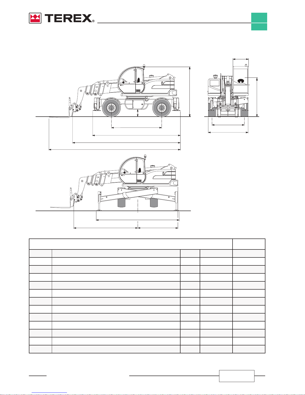
2.1 MAIN DIMENSIONS
Gyro 4020 Gyro 4518
A Overall height mm 3020 3020
B Height to the steering wheel mm 2135 2135
C Overall width mm 2430 2430
D Cab width mm 910 910
E Track mm 1950 1950
F Wheel-base mm 3030 3030
G Length to the front tyres mm 5280 5280
H Length to the attachment holding plate mm 7085 6485
I Ground clearance mm 440 440
L Max width with extended outriggers mm 5015 5015
M Rear reach from the rotation centre mm 2425 2425
N Front reach from the rotation centre mm 4445 3485
O Length to the forks mm 8500 7900
F
E
C
B
A
D
I
G
N M
L
H
O
 Loading...