

Terex Genie Z-34/22 IC Service And Repair Manual

Service and Repair Manual
Serial Number Range
Z-34/22 IC
from Z3406-4800
This manual includes:
Repair procedures
Fault
Electrical and
Hydraulic Schematics
For detailed maintenance
procedures, refer to the
appropriate Maintenance
Manual for your machine.
Part No. 1268527
Rev A
September 2015
Codes

Service and Repair Manual September 2015
Introduction
Introducti on Introducti on
Important
Read, understand and obey the safety rules and
operating instructions in the appropriate Operator's
Manual on your machine before attempting any
procedure.
This manual provides troubleshooting and repair
procedures for qualified service professionals.
Basic mechanical, hydraulic and electrical skills
are required to perform most procedures. However,
several procedures require specialized skills, tools,
lifting equipment and a suitable workshop. In these
instances, we strongly recommend that
maintenance and repair be performed at an
authorized Genie dealer service center.
Technical Publications
Genie has endeavored to deliver the highest
degree of accuracy possible. However, continuous
improvement of our products is a Genie policy.
Therefore, product specifications are subject to
change without notice.
Readers are encouraged to notify Genie of errors
and send in suggestions for improvement. All
communications will be carefully considered for
future printings of this and all other manuals.
Contact Us:
Internet: www.genielift.com
E-mail: awp.techpub@terex.com
Compliance
Machine Classification
Group B/Type 3 as defined by ISO 16368
Machine Design Life
Unrestricted with proper operation, inspection and
scheduled maintenance.
Find a Manual for this Model
Go to http://www.genielift.com
Use the links to locate Operator's, Parts,
Maintenance, and Service and Repair manuals.
Copyright © 2015 by Terex Corporation
1268527 Rev A, September 2015
First Edition, First Printing
Genie is a registered trademark of Terex South Dakota, Inc. in
the U.S.A. and many other countries.
“Z” is a trademark of Terex South Dakota, Inc.
ii Z-34/22 IC Part No. 1268527

September 2015 Service and Repair Manual
Revision
Date
Section
Procedure / Page / Description
Introduction
Revision History
A 9/2015
Release
Reference Examples:
Section – Repair Procedure, 4-2
Section – Fault Codes, All charts
Section – Schematics, Legends and schematics
Part No. 1268527 Z-34/22 IC iii
Click on any content or procedure in the Table of Contents to view
Electronic Version
the update.
Service and Repair Manual September 2015
Introduction
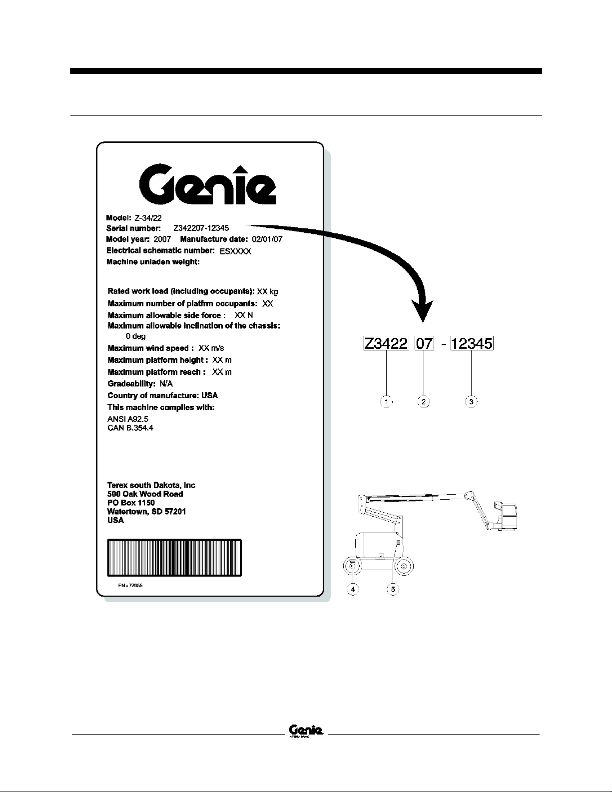
Serial Number Legend
1 Model
2 Model year
3 Sequence number
4 Serial number (stamped on chassis)
iv Z-34/22 IC Part No. 1268527
5 Serial label

September 2015 Service and Repair Manual
Safety Rules
Section 1 Safety Rules
Danger
Failure to obey the instructions and safety rules in
this manual and the appropriate Operator's Manual
on your machine will result in death or serious
injury.
Many of the hazards identified in the operator's
manual are also safety hazards when maintenance
and repair procedures are performed.
Do Not Perform Maintenance
Unless:
You are trained and qualified to perform
maintenance on this machine.
You read, understand and obey:
• manufacturer's instructions and safety rules
• employer's safety rules and worksite
regulations
• applicable governmental regulations
You have the appropriate tools, lifting
equipment and a suitable workshop.
Part No. 1268527 Z-34/22 IC v
Service and Repair Manual September 2015
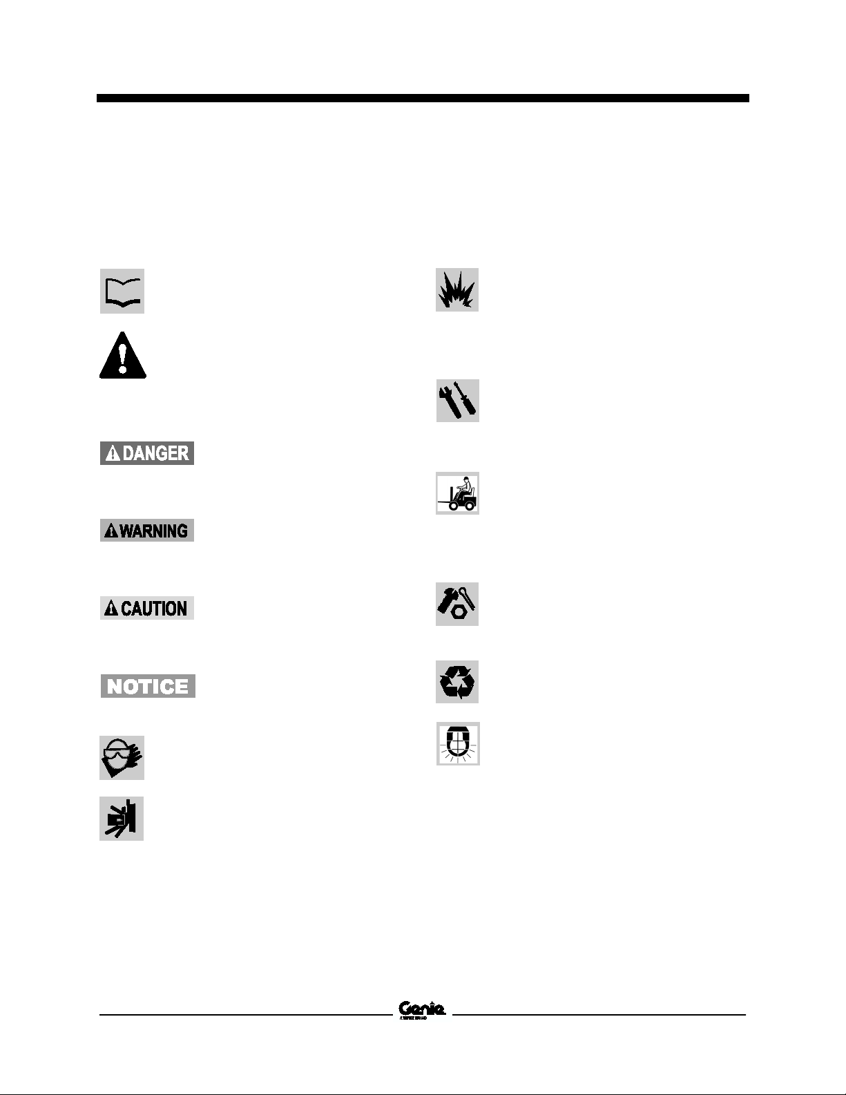
Read each procedure thoroughly. This
manual and the decals on the machine,
use signal words to identify the following:
Safety alert symbol
alert
personal injury hazards. Obey all
safety messages that follow this
symbol to avoid possible injury or
death.
Indicates a imminently hazardous
situation which, if not avoided,
will result in death or serious
injury.
Indicates a
situation which, if not avoided,
could result in death or serious
injury.
Indicates a potentially hazardous
situation which, if not avoided,
may cause minor or moderate
injury.
Indicates a potentially hazardous
situation which,
may result in property damage.
Be sure to wear protective eye wear and
other protective clothing if the situation
warrants it.
Be aware of potential crushing hazards
such as moving parts, free swinging or
unsecured components when lif
placing loads. Always wear approved
steel
Be sure to keep sparks, flames and
lighted tobacco away from flammable and
combustible materials like battery gases
and engine fuels. Always have an
approved fire extinguisher within easy
reach.
Be sure that all tools and working areas
are properly
use. Keep work surfaces clean and free
of debris that could get into machine
components and cause damage.
Be sure any forklift, overhead crane or
other lifting or supporting device is fully
capable of supporting and stabilizing
weight to be lifted. Use only chains or
straps that are in good condition and of
ample capacity.
Be sure that fasteners intended for one
time use (i.e., cotter pins and self
nuts) are not reused. These components
may fail if they are used a
Be sure to properly dispose of old oil or
other fluids. Use an approved container.
Please be environmentally safe.
Be sure that your workshop or work area
is properly ventilated and well lit.
Safety Rules
Personal Safety
Any person working on or around a machine must
be aware of all known safety hazards. Personal
safety and the continued safe operation of the
machine should be your top priority.
—used to
personnel to potential
potentially hazardous
Workplace Safety
Any person working on or around a machine must
be aware of all known safety hazards. Personal
safety and the continued safe operation of the
machine should be your top priority.
maintained and ready for
the
-toed shoes.
vi Z-34/22 IC Part No. 1268527
if not avoided,
ting or
-locking
second time.

September 2015
Table of Contents
Introduction Introduction ........................................................................................................... ii
Important Information ............................................................................................. ii
Find a Manual for this Model .................................................................................. ii
Revision History..................................................................................................... iii
Serial Number Legend .......................................................................................... iv
Section 1 Safety Rules .......................................................................................................... v
General Safety Rules ............................................................................................. v
Section 2 Specifications ....................................................................................................... 1
Machine Specifications ........................................................................................... 1
Performance Specifications .................................................................................... 2
Hydraulic Specification ........................................................................................... 2
Hydraulic Component Specifications...................................................................... 4
Machine Torque Specifications .............................................................................. 6
Kubota D-905 Engine Specifications ...................................................................... 7
Kubota DF-752 Engine Specifications ................................................................... 8
Perkins 403C-11 Engine Specifications ................................................................. 9
Hydraulic Hose and Fitting Torque Specifications ............................................... 10
Torque Procedure ................................................................................................ 11
SAE and Metric Fasteners Torque Charts ........................................................... 12
Part No. 1268527 Z-34/22 IC vii

September 2015
Table of Contents
Section 3 Repair Procedures ............................................................................................. 13
Introduction .......................................................................................................... 13
Platform Controls ............................................................................................... 15
1-1 Drive Joystick ................................................................................................. 15
How to Adjust the Drive Joystick .................................................................... 15
1-2 Boom Function Speed Controller Adjustments .............................................. 17
Boom Function Speed Controller Adjustments ............................................... 17
Platform Components ....................................................................................... 19
2-1 Platform Leveling Slave Cylinder ................................................................... 19
How to Remove the Platform Leveling Slave Cylinder ................................... 19
How to Bleed the Leveling Slave Cylinder ...................................................... 19
2-2 Platform Rotator ............................................................................................. 20
How to Remove the Platform Rotator ............................................................. 20
How to Bleed the Platform Rotator ................................................................. 21
2-3 Platform Overload System ............................................................................. 22
How to Calibrate the Platform Overload System (if equipped) ....................... 22
Jib Boom Components ...................................................................................... 24
3-1 Jib Boom ........................................................................................................ 24
How to Remove the Jib Boom ........................................................................ 24
3-2 Jib Boom Bell Crank ...................................................................................... 25
How to Remove the Jib Boom Bell Crank ...................................................... 25
3-3 Jib Boom Lift Cylinder .................................................................................... 25
How to Remove the Jib Boom Lift Cylinder .................................................... 25
viii Z-34/22 IC Part No. 1268527

September 2015
Table of Contents
Primary Boom Components .............................................................................. 27
4-1 Cable Track .................................................................................................... 27
How to Repair the Primary Boom Cable Track ............................................... 27
4-2 Primary Boom................................................................................................. 27
How to Shim the Primary Boom ...................................................................... 27
How to Remove the Primary Boom ................................................................. 28
How to Disassemble the Primary Boom ......................................................... 30
4-3 Primary Boom Lift Cylinder ............................................................................ 31
How to Remove the Primary Boom Lift Cylinder ............................................. 31
4-4 Primary Boom Extension Cylinder ................................................................. 32
How to Remove the Primary Boom Extension Cylinder.................................. 32
4-5 Platform Leveling Master Cylinder ................................................................. 34
How to Remove the Platform Leveling Master Cylinder ................................. 34
Secondary Boom Components ......................................................................... 36
5-1 Secondary Boom ............................................................................................ 37
How to Disassemble the Secondary Boom ..................................................... 37
5-2 Secondary Boom Lift Cylinders ...................................................................... 40
How to Remove the Secondary Boom Lift Cylinders ...................................... 40
Engines ................................................................................................................ 42
6-1 Kubota Diesel Models .................................................................................... 42
Timing Adjustment .......................................................................................... 42
How to Check the Glow Plugs ......................................................................... 42
RPM Adjustment ............................................................................................. 42
How to Remove the Flex Plate........................................................................ 43
How to Install the Flex Plate ............................................................................ 43
Coolant Temperature and Oil Pressure Switches ........................................... 43
Part No. 1268527 Z-34/22 IC ix

September 2015
Table of Contents
6-2 Kubota Gasoline / LPG Models ..................................................................... 44
Choke Adjustment .......................................................................................... 44
Timing Adjustment .......................................................................................... 44
Carburetor Adjustment .................................................................................... 44
RPM Adjustment ............................................................................................. 44
How to Remove the Flex Plate ....................................................................... 45
How to Install the Flex Plate ........................................................................... 45
Coolant Temperature and Oil Pressure Switches .......................................... 45
6-3 Perkins Diesel Models ................................................................................... 46
Timing Adjustment .......................................................................................... 46
RPM Adjustment ............................................................................................. 46
How to Remove the Flex Plate ....................................................................... 47
How to Install the Flex Plate ........................................................................... 47
Coolant Temperature and Oil Pressure Switches .......................................... 47
Hydraulic Pumps ................................................................................................ 49
7-1 Auxiliary Pump ............................................................................................... 49
How to Test the Auxiliary Pump ...................................................................... 49
How to Remove the Auxiliary Pump ............................................................... 49
7-2 Function Pump ............................................................................................... 50
How to Test the Function Pump ..................................................................... 50
How to Removet the Function Pump .............................................................. 50
7-3 Drive Pump .................................................................................................... 51
How to Remove the Drive Pump .................................................................... 51
How to Prime the Drive Pump ........................................................................ 51
x Z-34/22 IC Part No. 1268527

September 2015
Table of Contents
Manifolds ............................................................................................................. 52
8-1 Function Manifold Components ..................................................................... 52
8-2 Valve Adjustments - Function Manifold .......................................................... 56
How to Adjust the Primary Boom Down Relief Valve...................................... 56
How to Adjust the Secondary Boom Down Relief Valve ................................. 56
8-3 Jib Boom and Platform / Jib Boom Rotate Manifold Components ................. 57
8-4 Brake/Two-Speed Manifold Components ...................................................... 58
8-5 Traction Manifold Components, 2WD ............................................................ 59
8-6 Traction Manifold Components, 4WD ............................................................ 60
8-7 Valve Adjustments, 4WD Traction Manifold ................................................... 62
8-8 Valve Coils ..................................................................................................... 63
How to Test a Coil ........................................................................................... 63
Valve Coil Resistance Specification ................................................................ 63
How to Test a Coil Diode ................................................................................ 64
Fuel and Hydraulic Tanks .................................................................................. 65
9-1 Fuel Tank ....................................................................................................... 65
How to Remove the Fuel Tank ........................................................................ 65
9-2 Hydraulic Tank ............................................................................................... 66
How to Remove the Hydraulic Tank................................................................ 66
Turntable Rotation Components ...................................................................... 67
10-1 Turntable Rotation Hydraulic Motor ............................................................. 67
How to Remove the Turntable Rotation Motor ................................................ 67
Axle Components ............................................................................................... 68
11-1 Hub and Bearings, 2WD Models .................................................................. 68
How to Remove the Hub and Bearings ........................................................... 68
How to Install the Hub and Bearings ............................................................... 68
Part No. 1268527 Z-34/22 IC xi

September 2015
Table of Contents
Section 4 Schematics ......................................................................................................... 69
Introduction .......................................................................................................... 69
Electrical Symbol Legend .................................................................................... 70
Hydraulic Symbols Legend .................................................................................. 71
Electrical Component and Wire Color Legends ................................................... 72
Electrical Schematics - Gasoline/LPG Models ................................................ 75
Electrical Schematic - Gasoline/LPG Models ...................................................... 76
Ground Control Box Switch Panel Wiring Diagram - Gasoline/LPG Models ....... 80
Ground Control Box Terminal Strip Wiring Diagram - Gasoline/LPG Models ..... 81
Platform Control Box Wiring Diagram - Gasoline/LPG Models ........................... 84
Electrical Schematics - Diesel Models ............................................................. 85
Electrical Schematic - Diesel Models ................................................................... 86
Ground Control Box Switch Panel Wiring Diagram - Diesel Models ................... 90
Ground Control Box Terminal Strip Wiring Diagram - Diesel Models .................. 91
Platform Control Box Wiring Diagram - Diesel Models ........................................ 94
Electrical Schematics - Options ....................................................................... 95
Platform Control Box Wiring Diagram - Options .................................................. 96
Manifold and Limit Switch Wiring Diagram .......................................................... 97
Hydraulic Schematics ........................................................................................ 99
Hydraulic Schematic, 2WD Models.................................................................... 100
Hydraulic Schematic, 4WD Models.................................................................... 104
xii Z-34/22 IC Part No. 1268527

September 2015 Service and Repair Manual
Tires and wheels
rough
terrain
industrial
Tire size
16.5 NHS 9-14.5 LT
Tire ply rating
8 Ply
Tread 6
Sidewall 6
Tire and wheel weight,
foam filled (minimum)
bs
g
bs
g
Overall tire diameter
n
m
n
m
Wheel diameter
n
m
n
m
Wheel width
n
m
n
m
Wheel lugs, 4WD
18
Wheel lugs, 2WD
Front
Rear
18
18
18
18
Lug nut torque, dry
lbs
170 Nm
lbs
170 Nm
Lug nut torque,
lubricated
lbs
129 Nm
lbs
129 Nm
si
ar
si
ar
Tires and wheels
Hi-flotation (option)
Tire size
15
Tire ply
8
Overall tire diameter
n
m
Wheel diameter
n
m
Wheel width
n
m
Wheel lugs
18
Lug nut torque, dry
lbs
170 Nm
Lug nut torque,
lubricated
lbs
129 Nm
Tire pressure,
si
ar
Fuel
LPG tank
ounds
g
Fuel tank
allons
iters
Hydraulic tank
allons
iters
Hydraulic system
(including tank)
allons
iters
Drive hubs
l oz
c
Drive hub oil type: SAE 9
API service classification GL5
Specifications
Section 2 Specificati ons
Machine Specifications
10-
175 l
30.5 i
16.5 i
10 i
9 @ 5/8 -
125 ft-
Tire pressure,
rough terrain
79 k
77.5 c
42 c
25.4 c
8 @ 5/8 9 @ 5/8 -
95 ft-
45 p
3.1 b
175 l
79 k
28 i
37 c
14.5 i
36.8 c
18 c
8 @ 5/8 9 @ 5/8 -
125 ft-
95 ft-
100 p
6.9 b
7 i
capacities
33.5 p
9.3 g
18 g
0 multipurpose hypoid gear oil
15.2 k
35.2 l
68.1 l
22 g
83.3 l
17 f
503 c
31-15.5-
rating
Part No. 1268527 Z-34/22 IC 1
31 i
78.7 c
15 i
38.1 c
13 i
33 c
9 @ 5/8 -
125 ft-
95 ft-
44 p
3 b
Service and Repair Manual September 2015
Drive speed, maximum
Stowed position
ph
m/h
ec
ec
Raised or extended
ph
m/h
ec
ec
Gradeability
See Operator's Manual
Braking distance, maximum
High range on paved surface
t
m
Joystick function speeds, maximum from platform
controls
Primary boom up
econds
Primary boom down
econds
Primary
econds
Primary boom retract
econds
Secondary boom up
econds
Secondary boom down
econds
Jib boom up
econds
Jib boom down
econds
Turntable rotate, 355°
econds
Platform rotate
econds
Hydraulic Fluid Specifications
Genie specifications require hydraulic oils which are
designed to give maximum protection to hydraulic
systems, have the ability to perform over a wide
temperature range, and the viscosity index
exceed 140. They should provide excellent antiwear,
oxidation prevention, corrosion inhibition, seal
conditioning, and foam and aeration suppression
properties.
Cleanliness level,
minimum
ISO 15/13
Water content,
maximum
pm
Recommended Hydraulic Fluid
Hydraulic oil type
Chevron Rando HD Premium
Viscosity grade
32
Viscosity index
200
Optional Hydraulic Fluids
Mineral based Shell Tellus S2 V 32
Shell Tellus S2 V 46
Shell Tellus S4 VX 32 Shell
Shell Donax TG (Dexron III)
Chevron 5606A
Biodegradable
46
Fire resistant
5046
Optional fluids may not have
the same hydraulic lifespan and
may result in component
damage.
Specifications
Performance Specifications
3.0 m
5.1 k
40 ft / 6.1 s
12.2 m / 6.1 s
0.6 m
0.98 k
40 ft / 45 s
12.2 m / 45 s
3 to 4 f
0.9 to 1.2
15 to 21 s
13 to 19 s
boom extend 14 to 20 s
14 to 20 s
15 to 21 s
11 to 17 s
24 - 30 s
15 to 21 s
62 to 72 s
4 - 7 s
For operational specifications, refer to the
Operator's Manual.
Hydraulic Oil Specifications
should
250 p
Petro Canada Environ MV
UCON Hydrolube HP-
Note: Genie specifications require additional
equipment and special installation instructions for
the approved optional fluids. Consult Genie
Product Support before use.
Continuous improvement of our products is a
Genie policy. Product specifications are
subject to change without notice or obligation.
2 Z-34/22 IC Part No. 1268527
Note: Extended machine operation can cause the
hydraulic fluid temperature to increase beyond it's
maximum allowable range. If the hydraulic fluid
temperature consistently exceeds 200°F / 90°C an
optional oil cooler may be required.
September 2015 Service and Repair Manual
Do not top off with incompatible
hydraulic fluids. Hydraulic fluids
may be incompatible due to the
differences in base additive
chemistry. When incompatible
fluids are mixed,
materials may form and deposit
in the hydraulic system,
plugging hydraulic lines, filters,
control valves and may result in
component damage.
ISO Grade
32
Viscosity index 200
Kinematic Viscosity
cSt @ 200°F / 100°C
cSt @ 104°F / 40°C
7.5
33.5
Brookfield Viscosity
cP @
cP @
1040
3310
Flash point 375°F / 190°C
Pour point
50°C
Maximum continuous operating
temperature
171°F / 77°C
ISO Grade
15
Viscosity index 300
Kinematic Viscosity
cSt @ 200°F / 100°C
cSt @ 104°F / 40°C
cSt @
5.5
15.0
510
Flash point 180°F / 82°C
Pour point
63°C
Maximum continuous operating
temperature
124°F / 51°C
Specifications
insoluble
Note: Do not operate the machine when the
ambient air temperature is consistently above
120°F / 49°C.
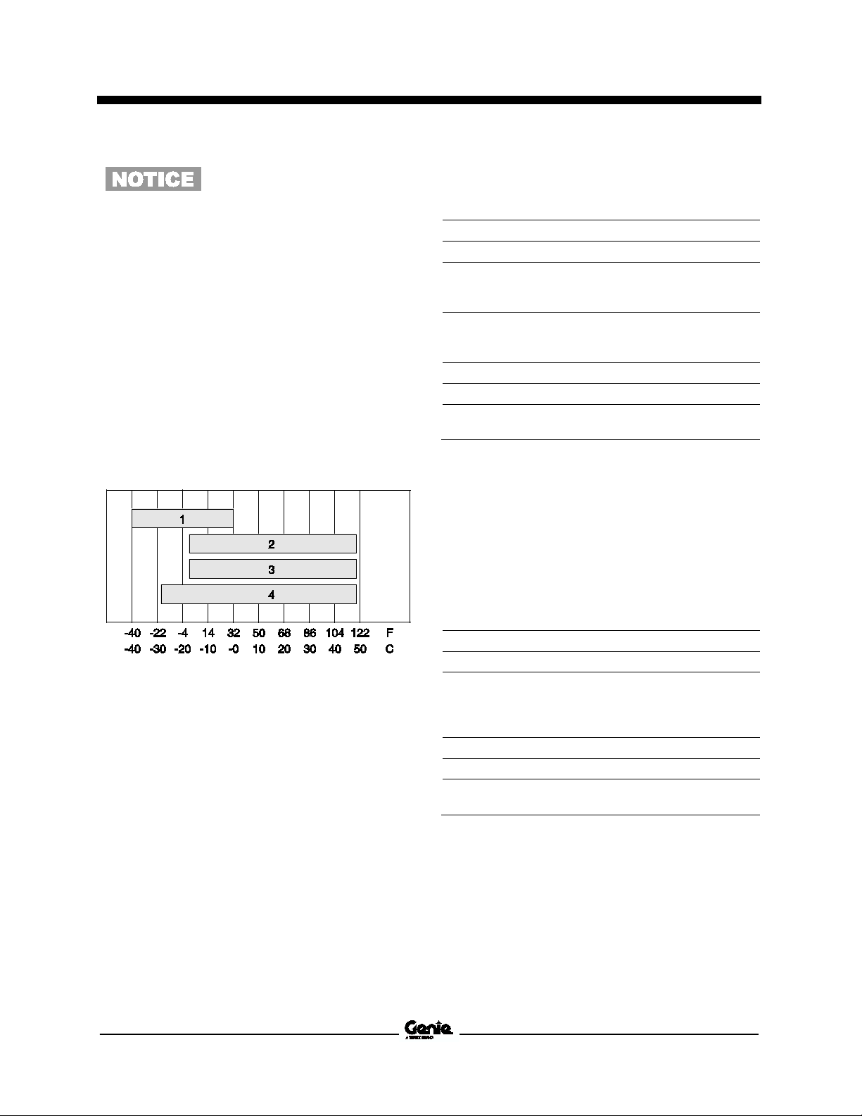
Hydraulic Fluid Temperature
Range
Chevron Rando HD Premium Oil
MV Fluid Properties
-4°F / -20°C
-22°F / -30°C
-58°F / -
Note: An hydraulic oil heating system is
recommended when the ambient temperature is
consistently below 0°F / -18°C.
Note: Do not operate the machine when the
ambient temperature is below -20°F / -29°C with
Rando HD Premium MV.
1 Chevron hydraulic oil 5606A
2 Petro-Canada Environ MV 46
3 UCON Hydrolube HP-5046D
4 Chevron Rando HD premium oil MV
Part No. 1268527 Z-34/22 IC 3
Ambient air temperature
Chevron 5606A Hydraulic Oil
Fluid Properties
Note: Use of Chevron 5606A hydraulic fluid, or
equivalent, is required when ambient temperatures
are consistently below 0°F / -17°C unless an oil
heating system is used.
-40°F / -40°C
-81°F / -
Service and Repair Manual September 2015
Continued use of Chevron
5606A hydraulic fluid, or
equivalent, when ambient
temperatures
above 32°F / 0°C may result in
component damage
ISO Grade
46
Viscosity index 154
Kinematic Viscosity
cSt @ 200°F / 100°C
cSt @ 104°F / 40°C
8.0
44.4
Flash point 482°F / 250°C
Pour point
45°C
Maximum continuous operating
temperature
180°F / 82°C
ISO Grade
46
Viscosity index 192
Kinematic Viscosity
cSt @ 149°F / 65°C
cSt @ 104°F / 40°C
cSt @ 0°F /
22
46
1300
Flash point None
Pour
63°C
Maximum continuous operating
temperature
189°F / 87°C
Drive Pump
Type: bi
c
pm
84 L/min
Function pump
(standard)
Displacement per revolution
c
Flow rate @ 300
pm
11.4 L/min
Function pump
(230V generator
Specifications
are consistently
Petro-Canada Environ MV 46
Fluid Properties
Hydraulic Component Specifications
-directional variable displacement piston pump
Displacement per revolution 1.71 cu in
28 c
Flow rate @ 3000 rpm 22 g
-49°F / -
UCON Hydrolube HP-5046 Fluid
Properties
-18°C
point -81°F / -
Type: fixed displacement gear pump
0.24 cu in
4 c
0 rpm 3 g
option)
Type: fixed displacement gear pump
Displacement per revolution 0.37 cu in
6 cc
Flow rate @ 3000 rpm 4.4 gpm
16.7 L/min
4 Z-34/22 IC Part No. 1268527

September 2015 Service and Repair Manual
Auxiliary Pump
Displacement per revolution
pm
1.9 L/min
Auxiliary pump relief pressure
si
ar
Function manifold
System relief valve pressure,
maximum
si
ar
Primary boom down relief valve
pressure
si
ar
Secondary boom down relief
valve pressure
si
ar
Steer flow regulator
pm
3.8 L/min
platform rotate flow
pm
1.1 L/min
Traction Manifold
si
ar
si
ar
Steer end drive motors (4WD models)
u in
c
Non
u in
c
Hydraulic Filters
Medium pressure filter
Beta 3 ˆ 200
Medium pressure filter bypass
pressure
si
ar
Hydraulic tank return filter
icron with
ar
bypass
Specifications
Type: fixed displacement gear pump
0.5 g
3400 p
1.0 g
regulator 0.3 g
Hot oil relief pressure
2WD
4WD
234.5 b
3200 p
220.6 b
1600 p
110 b
1600 p
110 b
170 p
11.7 b
150 p
10.3 b
-steer end drive motors
Displacement per revolution 1.53 c
10 m
25 psi / 1.7 b
25 c
50 p
3.4 b
Displacement per revolution 1.53 c
25 c
Part No. 1268527 Z-34/22 IC 5

Service and Repair Manual September 2015
Platform Rotator
3/4
3/4
lbs
515 Nm
lbs
379 Nm
3/8
3/8
lbs
60 Nm
lbs
45 Nm
Turntable rotate assembly
Rotate bearing mounting bolts, lubricated
lbs
244 Nm
Rotate bearing motor mounting bolts,
lubricated
lbs
126 Nm
Drive motors and hubs
Drive hub mounting bolts, lubricated
lbs
244 Nm
Drive motor mounting bolts, lubricated
3/8
7/16
lbs
31 Nm
lbs
50 Nm
Specifications
Machine Torque Specifications
-10 center bolt, GR 8, dry
-10 center bolt, GR 8, lubricated
-16 outer bolts, GR 8, dry
-16 outer bolts, GR 8, lubricated
-16, GR5
-14, GR5
380 ft-
280 ft-
44 ft-
33 ft-
180 ft-
93 ft-
180 ft-
23 ft-
37 ft-
6 Z-34/22 IC Part No. 1268527

September 2015 Service and Repair Manual
Displacement
u in
Number of cylinders
3
Bore and Stroke
nches
m
Horsepower, gross
intermittent
pm
pm
Firing order
3
Low idle
pm
260 Hz
High idle
pm
600 Hz
Compression ratio
23:1
Compression pressure
si
ar
Governor
centrifugal mechanical
Valve Clearance, cold
n
m
Lubrication system
Oil pressure
si
ar
Oil capacity
(including filter)
uarts
Oil viscosity requirements
-
30 (synthetic)
-
40
Above 23° F /
50
Unit ships with 15W
temperatures may require the use of alternative engine
oils. For oil requirements, refer to the Engine Operator
Manual for your engine.
Engine coolant
Capacity
uarts
Fuel injection system
Injection pump make
Bosch MD
Injection pump pressure,
maximum
si
ar
Injection timing
13° to 25° BTDC
Fuel requirement
For fuel requirements, refer to the engine Operator
Manual for
Starter motor
Cranking speed
300 RPM
Current draw, normal load
155A
Battery
Type
12V DC
Group
34/78
Quantity
1
Ampere hour 75AH
Cold cranking ampere
900A
Reserve capacity @ 25A rate
inutes
Alternator output
30A @ 12V DC
Fan belt deflection
nch
m
Specifications
Kubota D-905 Engine
36 to 64 p
54.86 c
0.90 liters
2.83 x 2.9 i
72 x 73.6 m
26 @ 2600 r
19.3 kW @ 2600 r
1 - 2 -
1300 r
3000 r
412 to 469 p
28.4 to 32.3 b
0.0057 to 0.0072 i
0.145 to 0.185 m
2.48 to 4.41 b
5.4 q
5.1 liters
1991 p
137 b
your engine.
200 -
125 m
1/4 to 3/8 i
7 to 9 m
22° F to 86° F/ -30° C to 30° C 5W-
4° F to 90° F / -20° C to 32° C 10W-
-5° C 20W-
-40. Extreme operating
3.3 q
Part No. 1268527 Z-34/22 IC 7
3.1 liters

Service and Repair Manual September 2015
Displacement
u in
iters
Number of cylinders
3
Bore and Stroke
nches
m
Horsepower
pm
pm
Firing order
3
Low idle
pm
320 Hz
High idle
pm
600 Hz
Compression ratio
9.2:1
Compression pressure
si
ar
Governor
centrifugal mechanical
Valve Clearance, cold
n
m
Lubrication system
Oil pressure
si
ar
Oil capacity
(including filter)
uarts
iters
Oil viscosity requirements
Below 86°F / 30°C
20
-
30
Above 14°F /
40
Unit ships with
temperatures may require the use of alternative engine
oils. For oil requirements, refer to the Engine Operator
Manual for your engine.
Fuel Pump
Fuel pressure, static
si
ar
Fuel flow rate
pm
0.47 L/min
Fuel requirement
For fuel requirements, refer to the engine Operator
Manual for your engine.
Alternator output
30A @ 12V DC
Fan belt deflection
n
m
Starter motor
Brush length, new
n
m
Brush length, minimum
n
m
Brush spring tension
unces
o 25.5 Newtons
Battery
Type
12V DC
Group
34/78
Quantity
1
Ampere hour 75AH
Cold cranking ampere 900A
Reserve capacity @ 25A rate
inutes
Engine coolant
Capacity
Ignition system
Ignition spark advance
18° BTDC
Ignition coil primary resistance
Ω
@ 75°F / 24°C
Ignition coil secondary
resistance
Ω
@ 75°F / 24°C
#1 Spark plug wire resistance
Ω
#2 Spark plug wire resistance
Ω
#3 Spark plug wire resistance
Ω
Spark plug type
11
Spark plug gap
n
m
Specifications
Kubota DF-752 Engine
2.68 x 2.68 i
24.8 @ 3600 r
18.5 kW @ 3600 r
0.0057 to 0.0072 i
0.145 to 0.183 m
28 to 64 p
5W-
4°F to 104°F / -20°C to 40°C 10W-
-10°C 15W-
15W-40. Extreme operating
2.84 p
0.125 g
45 c
0.74 l
68 x 68 m
1 - 2 -
1600 r
3000 r
128 to 185 p
8.8 to 12.7 b
1.9 to 4.4 b
3.4 q
3.25 l
0.19 b
1/4 to 3/8 i
7 to 9 m
0.669 i
17 m
0.453 i
11.5 m
50 to 91 o
13.7 t
125 m
3.1 quarts
2.9 liters
1.3 to 1.6
10.7 to 14.5 k
2.81 to 4.79 k
3.4 to 5.8 k
3.57 to 6.09 k
NGK BKR4E-
0.039 to 0.043 i
1 to 1.1 m
8 Z-34/22 IC Part No. 1268527

September 2015 Service and Repair Manual
Displacement
u in
iters
Number of cylinders
3
Bore and Stroke
nches
m
Horsepower
pm
pm
Firing order
3
Low idle
pm
300 Hz
High idle
pm
600 Hz
Compression ratio
23:1
Compression pressure
si
ar
Pressure (psi) of
3.4
Governor
mechanical, all speed
Valve Clearance, cold
n
m
Lubrication system
Oil pressure
si
ar
Oil capacity
(including filter)
uarts
iters
Oil viscosity requirements
Below 86°F / 30°C
20
-
30
Above 14°F /
40
Unit ships with 15W
temperatures may require the use of alternative engine
oils. For oil requirements,
Manual for your engine.
Fuel injection system
Injection pump make
Bosch
Injection timing
23° BTDC @
pm
Injection pressure
si
ar
Fuel requirement
For fuel requirements, refer to the engine Operator
Manual for your engine.
Alternator output
40A @ 12V DC
Fan belt deflection
n
m
Starter motor
Current draw, normal load
150A
Battery
Type 12V DC, Group 34/78
Quantity
1
Ampere hour 75AH
Cold cranking ampere
900A
Reserve capacity
inutes
Engine coolant
Capacity
uarts
iters
Specifications
Perkins 403C-11 Engine
3.03 x 3.19 i
19.5 kW @ 3000 r
lowest cylinder must be within 50 psi /
5 bar of highest cylinder
40 to 60 p
5W-
4°F to 104°F / -20°C to 40°C 10W-
-10°C 15W-
69 c
1.13 l
77 x 81 m
26 @ 3000 r
1 - 2 -
1500 r
3000 r
425 p
29.3 b
0.008 i
0.2 m
2.76 to 4.1 b
4.3 q
4.07 l
-40. Extreme operating
refer to the Engine Operator
3000 r
2133 p
147 b
3/8 i
10 m
100 -
@ 25A rate 125 m
3.28 q
3.1 l
Part No. 1268527 Z-34/22 IC 9
Service and Repair Manual September 2015
SAE Dash Size
Torque
Specifications
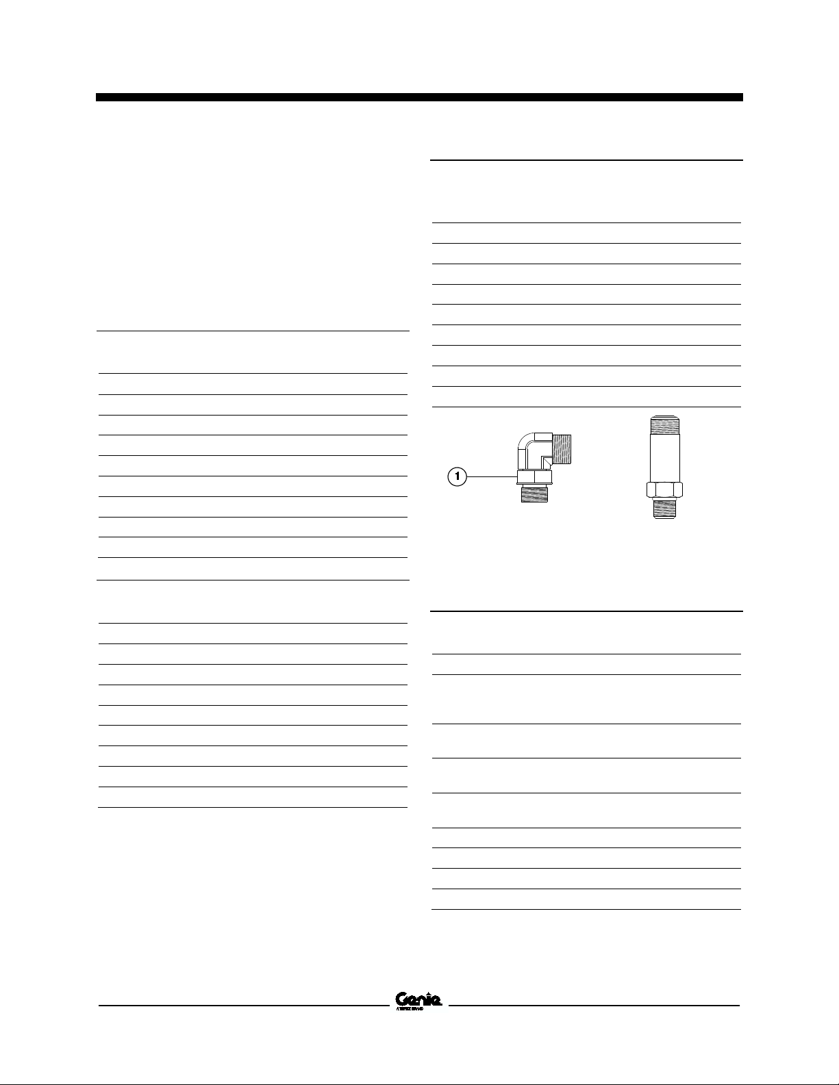
Hydraulic Hose and Fitting Torque Specifications
Your machine is equipped with Parker Seal-Lok™
ORFS or 37° JIC fittings and hose ends. Genie
specifications require that fittings and hose ends
be torqued to specification when they are removed
and installed or when new hoses or fittings are
installed.
Seal-Lok™ Fittings
(hose end - ORFS)
-4 10 ft-lbs / 13.6 Nm
-6 30 ft-lbs / 40.7 Nm
-8 40 ft-lbs / 54.2 Nm
-10 60 ft-lbs / 81.3 Nm
-12 85 ft-lbs / 115 Nm
-16 110 ft-lbs / 150 Nm
-20 140 ft-lbs / 190 Nm
-24 180 ft-lbs / 245 Nm
JIC 37° Fittings
(swivel nut or hose connection)
SAE Dash Size Thread Size Flats
-4 7/16-20 2
-6 9/16-18 1 ¼
-8 3/4-16 1
-10 7/8-14 1
-12 1 1/16-12 1
-16 1 5/16-12 1
-20 1 5/8-12 1
-24 1 7/8-12 1
SAE O-ring Boss Port
(tube fitting - installed into Aluminum)
(all types)
SAE Dash Size Torque
-4 14 ft-lbs / 19 Nm
-6 23 ft-lbs / 31.2 Nm
-8 36 ft-lbs / 54.2 Nm
-10 62 ft-lbs / 84 Nm
-12 84 ft-lbs / 114 Nm
-16 125 ft-lbs / 169.5 Nm
-20 151 ft-lbs / 204.7 Nm
-24 184 ft-lbs / 249.5 Nm
Adjustable Fitting Non-adjustable fitting
1 jam nut
SAE O-ring Boss Port
(tube fitting - installed into Steel)
SAE Dash Size Torque
-4 ORFS / 37° (Adj)
ORFS (Non-adj)
37° (Non-adj)
-6 ORFS (Adj / Non-adj)
37° (Adj / Non-adj)
-8 ORFS (Adj / Non-adj)
37° (Adj / Non-adj)
-10 ORFS (Adj / Non-adj)
37° (Adj / Non-adj)
-12 (All types) 135 ft-lbs / 183 Nm
-16 (All types) 200 ft-lbs / 271.2 Nm
-20 (All types) 250 ft-lbs / 339 Nm
-24 (All types) 305 ft-lbs / 413.5 Nm
15 ft-lbs / 20.3 Nm
26 ft-lbs / 35.3 Nm
22 ft-lbs / 30 Nm
35 ft-lbs / 47.5 Nm
29 ft-lbs / 39.3 Nm
60 ft-lbs / 81.3 Nm
52 ft-lbs / 70.5 Nm
100 ft-lbs / 135.6 Nm
85 ft-lbs / 115.3 Nm
10 Z-34/22 IC Part No. 1268527
September 2015 Service and Repair Manual
Specifications
Torque Procedure
Seal-Lok™ fittings
1 Replace the O-ring. The O-ring must be
replaced anytime the seal has been broken.
The O-ring cannot be re-used if the fitting or
hose end has been tightened beyond finger
tight.
Note: The O-ring in Parker Seal Lok™ fittings and
hose end are custom-size O-rings. They are not
standard size O-rings. They are available in the
O-ring field service kit (Genie part number 49612).
2 Lubricate the O-ring before installation.
3 Be sure the O-ring face seal is seated and
retained properly.
4 Position the tube and nut squarely on the face
seal end of the fitting, and tighten the nut
finger tight.
5 Tighten the nut or fitting to the appropriate
torque. Refer to the appropriate torque chart
in this section.
6 Operate all machine functions and inspect the
hose, fittings and related components to
confirm there are no leaks.
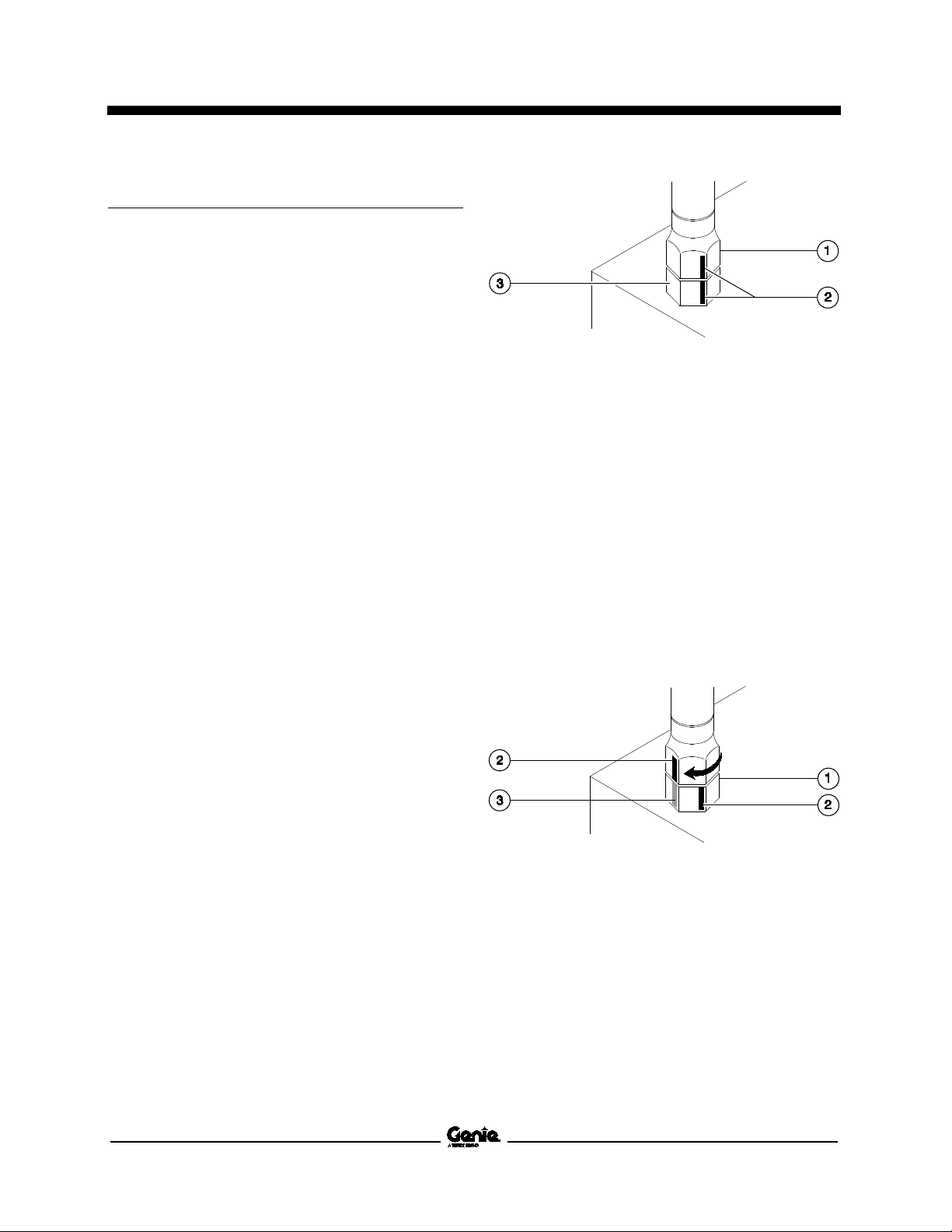
1 hex nut
2 reference mark
3 body hex fitting
3 Working clockwise on the body hex fitting,
make a second mark with a permanent ink
marker to indicate the proper tightening
position. Refer to Illustration 2.
Note: Use the JIC 37° Fitting table in this section to
determine the correct number of flats, for the
proper tightening position.
Note: The marks indicate the correct tightening
positions have been determined. Use the second
mark on the body hex fitting to properly tighten the
joint after it has been loosened.
Illustration 1
JIC 37° fittings
1 Align the tube flare (hex nut) against the nose
of the fitting body (body hex fitting) and tighten
the hex nut to the body hex fitting to hand
tight, approximately 30 in-lbs / 3.4 Nm.
2 Using a permanent ink marker, make a
reference mark on one the flats of the hex nut
and continue the mark onto the body of the
hex fitting. Refer to Illustration 1.
1 body hex fitting
2 reference mark
3 second mark
4 Tighten the hex nut until the mark on the hex
nut is aligned with the second mark on the
body hex fitting.
5 Operate all machine functions and inspect the
hose, fittings and related components to
confirm there are no leaks.
Part No. 1268527 Z-34/22 IC 11
Illustration 2
Service and Repair Manual September 2015
Specifications
12 Z-34/22 IC Part No. 1268527

September 2015 Service and Repair Manual
Repair Procedures
Section 3 Repair Proc edur es
Observe and Obey:
Repair procedures shall be completed by a
person trained and qualified on the repair of
this machine.
Immediately tag and remove from service a
damaged or malfunctioning machine.
Repair any machine damage or malfunction
before operating the machine.
Before Repairs Start:
Read, understand and obey the safety rules
and operating instructions in the appropriate
operator's manual on your machine.
Machine Configuration:
Unless otherwise specified, perform each
repair procedure with the machine in the
following configuration:
• Machine parked on a firm, level surface
• Key switch in the off position with the key
removed
• The red Emergency Stop button in the off
position at both ground and platform
controls
• Wheels chocked
• All external AC power supply disconnected
from the machine
• Boom in the stowed position
• Turntable secured with the turntable rotation
lock
Be sure that all necessary tools and parts are
available and ready for use.
Use only Genie approved replacement parts.
Read each procedure completely and adhere
to the instructions. Attempting shortcuts may
produce hazardous conditions.
Part No. 1268527 Z-34/22 IC 13

Service and Repair Manual September 2015
Safety alert symbol—used to alert
personnel to potential personal
injury hazards. Obey all safety
messages that follow this symbol
to avoid possible injury or death.
Indicates a imminently hazardous
situation which, if not avoided, will
result in death or serious injury.
Indicates a potentially hazardous
situation which, if not avoided,
could res
injury.
Indicates a potentially hazardous
situation which, if not avoided,
may cause minor or moderate
injury.
Indicates a potentially hazardous
situation which, if not avoided,
may result in property damage.
Repair Procedures
About This Section
Most of the procedures in this section should only
be performed by trained service professional in a
suitably equipped workshop. Select the
appropriate repair procedure after troubleshooting
the problem.
Perform disassembly procedures to the point
where repairs can be completed. Then to
re-assemble, perform the disassembly steps in
reverse order.
Symbols Legend
ult in death or serious
Indicates that a specific result is expected
after performing a series of steps.
Indicates that an incorrect result has occurred
after performing a series of steps.
14 Z-34/22 IC Part No. 1268527
September 2015 Service and Repair Manual
Electrocution/burn hazard.
Contact with electrically charged
circuits could result in death or
serious injury. Remove all rings,
watches and other jewelry.
Platform Controls
1-1 Drive Joystick
The drive joystick is connected to the drive motor
controller, located under the drive chassis cover at
the non-steer end of the machine. Maintaining the
boom function speed controller at the proper
settings is essential to safe machine operation.
The boom function speed controller should operate
smoothly and provide proportional speed control
through its entire range of motion. For further
information or assistance, contact the Genie
Product Support.
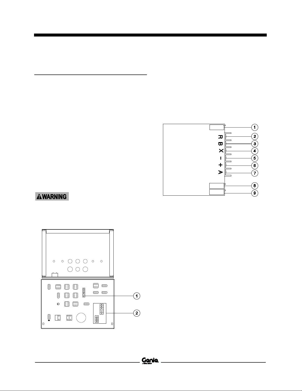
How to Adjus t t he D riv e Joy sti ck
How to Adjust the Drive Joystick
Note: Perform this procedure with the engine off.
1 Remove the fasteners from the platform
control box lid.
3 Locate and disconnect the wire connected to
terminal "A" on the drive joystick circuit board.
4 Set a multimeter to read DC current.
Note: The multimeter, when set to read DC current,
should be capable of reading up to 1200 mA.
5 Connect the black(-) lead from the multimeter
to the wire that was just disconnected.
Connect the red(+) lead of the multimeter to
terminal "A" on the joystick.
2 Open the control box lid and locate the drive
joystick.
1 low range potentiometer
2 terminal "R", activates low range
3 terminal "B", drive reverse
4 terminal "X", brake release
5 terminal "-", ground
6 terminal "+", positive
7 terminal "A", drive forward
8 threshold potentiometer
9 high range potentiometer
6 Turn the keyswitch to platform controls and
pull out the red Emergency Stop button out to
the on position at both the ground and
platform controls. Do not start the engine.
1 boom function speed controller
2 drive joystick
Part No. 1268527 Z-34/22 IC 15

Service and Repair Manual September 2015
Platform Controls
Set the threshold:
Set the stowed drive speed:
Note: The drive joystick adjustments are not final
adjustments. Final adjustments will need to be
made to meet drive speed specifications. Refer to
Section 2, Specifications.
7 Press down the foot switch. Move the drive
joystick off center in either direction just until a
current reading appears on the mulitmeter
display.
8 Hold the drive joystick in position and adjust
the threshold potentiometer until the
multimeter displays approximately 600 mA.
Set the high range:
9 Press down the foot switch. Move and hold
the drive joystick full stroke in either direction.
10 Hold the drive joystick in position and adjust
the hi range potentiometer until the multimeter
displays slightly higher than 1100 mA.
Set the low range:
11 Start the engine from the platform controls
and raise the primary boom approximately
3 feet / 1 m. Turn the engine off.
12 Press down the foot switch. Move and hold
the drive joystick full stroke in either direction.
13 Hold the drive joystick in position and adjust
the lo range potentiometer until the multimeter
displays approximately 700 mA.
14 Push in the red Emergency Stop button to the
off position at the platform controls.
Note: Select a test area that is firm, level and free
of obstructions.
17 Pull out the red Emergency Stop button out to
the on position at both the ground and
platform controls.
18 Create start and finish lines by marking two
lines on the ground 40 feet / 12.2 m apart.
19 Start the engine from the platform controls
and move the engine idle select switch to foot
switch activated high idle (rabbit and foot
switch symbol).
20 Choose a point on the machine; i.e., contact
patch of a tire, as a visual reference for use
when crossing the start and finish lines.
21 Bring the machine to top drive speed before
reaching the start line. Begin timing when your
reference point on the machine crosses the
start line.
22 Continue at full speed and note the time when
the machine reference point passes over the
finish line. Refer to Section 2, Specifications.
Result: The stowed drive speed does not
meet specification. Adjust the hi range
potentiometer on the drive joystick clockwise
to increase the speed or counterclockwise to
decrease the stowed drive speed. Continue to
perform steps 20 through 22 until the stowed
drive speed meets specification.
15 Disconnect the multimeter.
16 Connect the wire that was disconnected in
step 3 to terminal "A" of the drive joystick.
16 Z-34/22 IC Part No. 1268527
September 2015 Service and Repair Manual
Electrocution/burn hazard.
Contact with electrically charged
circuits could result in death or
serious injury. Remove all rings,
watches and other jewelry.
Platform Controls
Set the raised drive speed:
Note: Select a test area that is firm, level and free
of obstructions.
23 Press down the foot switch and raise the
primary boom approximately 3 feet / 1 m.
24 Choose a point on the machine; i.e., contact
patch of a tire, as a visual reference for use
when crossing the start and finish lines.
25 Bring the machine to top drive speed before
reaching the start line. Begin timing when your
reference point on the machine crosses the
start line.
26 Continue at full speed and note the time when
the machine reference point passes over the
finish line. Refer to Section 2, Specifications.
Result: The raised drive speed does not meet
specification. Adjust the lo range
potentiometer on the drive joystick clockwise
to increase the speed or counterclockwise to
decrease the raised drive speed. Continue to
perform steps 24 through 26 until the raised
drive speed meets specification.
1-2
Boom Function Speed Controller
Boom Functi on Spe ed C ontr oll er Adjus tm ents
Boom Function Speed Controller Adjustments
Note: Do not adjust the boom function speed
controller unless the static battery supply voltage is
above 24V DC.
1 Turn the key switch to platform controls and
pull out the red Emergency Stop button to the
on position at both the ground and platform
controls.
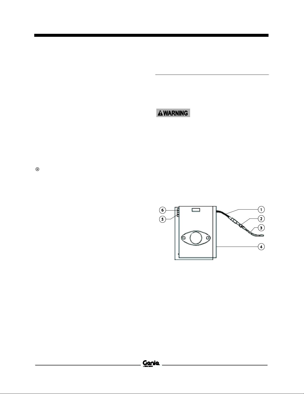
2 Open the platform control box lid and locate
the boom function speed controller.
27 Lower the primary boom to the stowed
position. Turn the engine off.
28 Close the platform control box lid and install
the fasteners.
1 black wire
2 diode
3 white/red wire
4 boom function speed controller
5 threshold trimpot
6 max out trimpot
Part No. 1268527 Z-34/22 IC 17

Service and Repair Manual September 2015
Boom function speed controller specifications
Threshold
o 6V DC
Max out
o 9V DC
Platform Controls
3 Locate the diode between the black wire from
the boom function speed controller and the
white/red wire.
4 Connect the red (+) lead from a volt meter to
the wire connector of the white/red wire next
to the diode. Connect the black (-) lead to
ground.
5 Turn the boom function speed controller to the
creep position.
6 Set the threshold: Press down the foot switch.
Move the primary boom toggle switch in the
up direction until the voltage reading appears.
Adjust the voltage to 5.5 to 6V DC. Turn the
threshold trimpot adjustment screw clockwise
to increase the voltage or counterclockwise to
decrease the voltage.
7 Turn the boom function speed controller to the
9 position.
8 Set the max-out: Press down the foot switch.
Move the primary boom toggle switch in the
up direction. Adjust the voltage to 8.5 to 9V
DC. Turn the max-out trimpot adjustment
screw clockwise to increase the voltage or
counterclockwise to decrease the voltage.
5 t
8.5 t
18 Z-34/22 IC Part No. 1268527
 Loading...