

Terex Genie AL5HT Service Manual

Service Manual
AL5HT
Part No. 1265482
Rev A
May 2015

Service Manual May 2015
Introduction
Introducti on Introducti on
Important
Read, understand and obey the safety rules and
operating instructions in the appropriate Operator's
Manual on your machine before attempting any
maintenance procedure.
This manual provides detailed scheduled
maintenance information for the machine owner
and user. It also provides troubleshooting and
repair procedures for qualified service
professionals.
Basic mechanical, hydraulic and electrical skills are
required to perform most procedures. However,
several procedures require specialized skills, tools,
lifting equipment and a suitable workshop. In these
instances, we strongly recommend that
maintenance and repair be performed at an
authorized Terex dealer service center.
Technical Publications
Terex has endeavored to deliver the highest
degree of accuracy possible. However, continuous
improvement of our products is a Terex policy.
Therefore, product specifications are subject to
change without notice.
Readers are encouraged to notify Terex of errors
and send in suggestions for improvement. All
communications will be carefully considered for
future printings of this and all other manuals.
Contact Us:
Internet: www.genielift.com
E-mail: awp.techpub@tere x .c om
Compliance
Machine Classification
Group A/Type 1 as defined by ISO 16368
Machine Design Life
Unrestricted with proper operatio n, inspec t ion and
scheduled maintenance.
Copyright © 2014 by Terex Corporation
1255863 Rev A, May 2015
First Edition, First Printing
'Terex' and 'AWP' are registered trademarks of Terex USA, LLC
in the U.S.A. and many other countries.
ii AL5HT Part No. 1265482
May 2015 Service Manual
Safety Rules
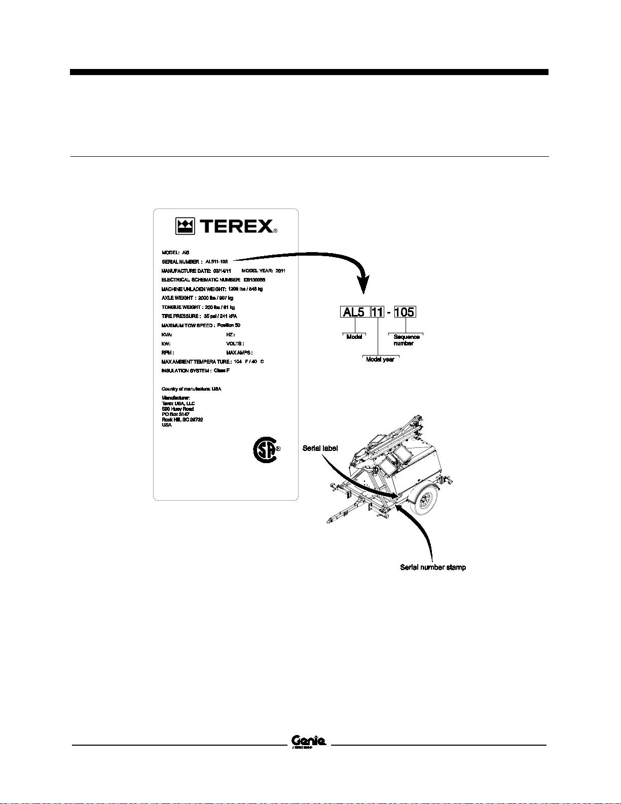
Serial Number Legend
Serial Number Legend
1 Model
2 Model year
3 Sequence number
4 Serial label (located on cabinet)
Part No. 1265482 AL5HT 3
5 Serial number (stamped on chassis)

Service Manual May 2015
Safety Rules
Section 1 Safety Rules
Danger
Failure to obey the instructions and safety rules in
this manual and the appropriate Operator's Manual
on your machine will result in death or serious
injury.
Many of the hazards identified in the operator's
manual are also safety hazards when maintenance
and repair procedures are performe d.
Do Not Perform Maintenance
Unless:
You are trained and qualified to perform
maintenance on this machine.
You read, understand and obey:
• manufacturer's instructions and safety rules
• employer's safety rules and worksite
regulations
• applicable governmental regulations
You hav e the appr o priat e tools , lift ing
equipment and a suitable workshop.
iv AL5HT Part No. 1265482
May 2015 Service Manual
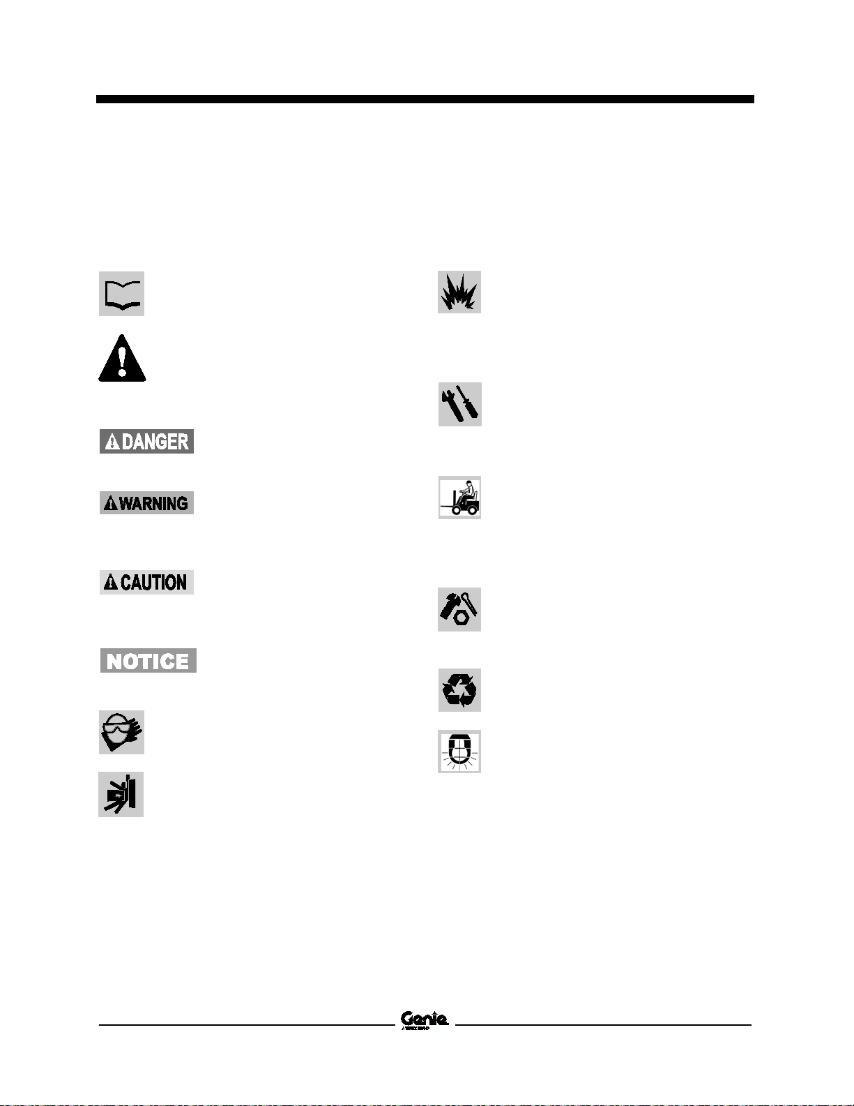
Read each procedure thoroughly. This
manual and the decals on the machine,
use signal words to identify the following:
Safety alert symbol—used to alert
personnel to potential personal
injury hazards. Obey all safety
messages that
to avoid possible injury or death.
Indicates a imminently hazardous
situation which, if not avoided, will
result in death or serious injury.
Indicates a potentially hazardous
situation which, if not avoided,
could result in death o
injury.
Indicates a potentially hazardous
situation which, if not avoided,
may cause minor or moderate
injury.
Indicates a potentially hazardous
situation which, if not avoided,
may result in property damage.
Be sure to wear protective
other protective clothing if the situation
warrants it.
Be aware of potential crushing hazards
such as moving parts, free swinging or
unsecured components when lifting or
placing loads. Always wear approved
steel
Be sure to keep sparks, flames and
lighted tobacco away from flammable and
combustible materials like battery gases
and engine fuels. Always have an
approved fire extinguisher within easy
reach.
Be sure that all tools and working areas
are properly maintained and ready for
use. Keep work surfaces clean and free of
debris
components and cause damage.
Be sure any forklift, overhead crane or
other lifting or supporting device is fully
capable of supporting and stabilizing the
weight to be lifted. Use only chains or
straps that are in good condi
ample capacity.
Be sure that fasteners intended for one
time use (i.e., cotter pins and self
nuts) are not reused. These components
may fail if they are used a second time.
Be sure to properly dispose of old oil or
other fluids.
Please be environmentally safe.
Be sure that your workshop or work area
is properly ventilated and well lit.
Safety Rules
Personal Safety
Any person working on or around a machine must
be aware of all known safety hazards. Personal
safety and the continued safe operation of the
machine should be your top priority.
follow this symbol
r serious
Workplace Safety
Any person working on or around a machine must
be aware of all known safety hazards. Personal
safety and the continued safe operation of the
machine should be your top priority.
that could get into machine
tion and of
-toed shoes.
eye wear and
-locking
Use an approved container.
Part No. 1265482 AL5HT v

May 2015
Table of Contents
Introduction Introduction .......................................................................................................... ii
Important Information .............................................................................................. ii
Serial Number Legend ......................................................................................... 3
Serial Number Legend ........................................................................................... 3
Section 1 Safety Rules ......................................................................................................... iv
General Safety Rules ............................................................................................. iv
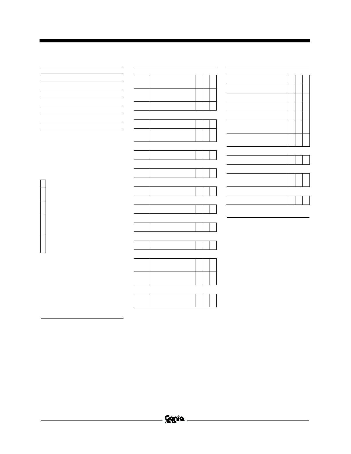
Section 2 Specifications ....................................................................................................... 1
Machine Specifications .......................................................................................... 1
Performance Specificatio ns ................................................................................... 1
Generator Options ................................................................................................. 1
Kubota D1105-E Engine Specifications ................................................................. 2
Kubota D1505-E Engine Specifications ................................................................. 3
Isuzu 4LE1 Engine Specifications .......................................................................... 4
Isuzu 4LE2 Engine Specifications .......................................................................... 5
Isuzu 4LE2-T Engine Specifications ...................................................................... 6
Machine Torque Specifications .............................................................................. 7
SAE and Metric Fasteners Torque Charts ............................................................. 8
vi AL5HT Part No. 1265482

May 2015
Table of Contents
Section 3 Scheduled Maintenance Procedures ................................................................. 9
Introduction ............................................................................................................. 9
Pre-Delivery Prepar at ion R eport .......................................................................... 12
Maintenance Inspection Report............................................................................ 13
Checklist A Procedures ..................................................................................... 15
A-1 Inspect the Manuals and Decals.................................................................... 15
A-2 Perform Pre-operat ion Ins pec ti on .................................................................. 16
A-3 Perform Function Tests ................................................................................. 16
A-4 Perform Engine Maintenance ........................................................................ 17
A-5 Perform Generator Maintenance ................................................................... 17
A-6 Perform Axle Maintenance ............................................................................ 18
A-7 Torque the Wheel Lug Nuts ........................................................................... 18
A-8 Perform Engine Maintenance ........................................................................ 19
A-9 Perform Coupler Maintenance ....................................................................... 19
A-10 Grease turntable bearing and rotate gear ................................................... 20
A-11 Perform Engine Maintenance ...................................................................... 20
A-12 Perform Engine Maintenance ...................................................................... 21
Checklist B Procedures ..................................................................................... 22
B-1 Inspect the Engine Start Battery .................................................................... 22
B-2 Inspect the Electrical Wiring .......................................................................... 23
B-3 Torque the Wheel Lug Nuts ........................................................................... 24
B-4 Perform Hydraulic Oil Analysis ...................................................................... 24
B-5 Perform Engine Maintenance ........................................................................ 25
B-6 Perform Engine Maintenance ........................................................................ 25
B-7 Perform Generator Maintenance ................................................................... 26
B-8 Perform Coupler Maintenance ....................................................................... 26
B-9 Perform Engine Maintenance ........................................................................ 27
B-10 Perform Axle Maintenance .......................................................................... 27
Part No. 1265482 AL5HT vii

May 2015
Table of Contents
Checklist C Procedures ..................................................................................... 28
C-1 Inspect the Tower Extend/Retract Cables and Pulleys ................................ 28
C-2 Perform Engine Maintenance........................................................................ 29
C-3 Perform Axle Maintenance ............................................................................ 29
C-4 Perform Engine Maintenance........................................................................ 30
C-5 Perform Engine Maintenance........................................................................ 30
Checklist D Procedures ..................................................................................... 31
D-1 Perform Engine Maintenance........................................................................ 31
D-2 Check the Tower Rotation Bearing Bolts ..................................................... 31
D-3 Replace the Hydraulic Return Filter .............................................................. 32
D-4 Perform Engine Maintenance........................................................................ 33
D-5 Perform Engine Maintenance........................................................................ 33
D-6 Perform Engine Maintenance........................................................................ 34
D-7 Perform Generator Maintenance .................................................................. 34
D-8 Perform Tongue Jack and Outrigger Jack Maintenance .............................. 35
D-9 Perform Axle Maintenance ............................................................................ 35
Checklist E Procedures ..................................................................................... 36
E-1 Perform Hydraulic Oil Analysis ...................................................................... 36
E-2 Perform Engine Maintenance ........................................................................ 37
E-3 Perform Engine Maintenance ........................................................................ 38
E-4 Perform Generator Maintenance ................................................................... 38
E-5 Perform Generator Maintenance ................................................................... 39
viii AL5HT Part No. 1265482

May 2015
Table of Contents
Section 4 Repair Procedures ............................................................................................. 40
Introduction ........................................................................................................... 40
Lighting ............................................................................................................... 42
1-1 How to Remove a Lamp ................................................................................. 42
1-2 How to Check Line Voltage ............................................................................ 42
1-3 How to Check the Open Circuit Voltage [Terex SM] ...................................... 43
Mast ..................................................................................................................... 44
2-1 How to Remove the Light Bar Assembly ....................................................... 44
2-2 How to Remove the Light Bar Lift Cylinder .................................................... 44
Tower Components ............................................................................................ 46
3-1 Tower Component ......................................................................................... 46
3-2 How to Remove the Cable Track .................................................................. 47
3-3 How to Remove the Tower Assembly ........................................................... 47
3-4 How to Disassemble the Tower .................................................................... 48
3-5 How to Remove the Tower Lift Cylinder ....................................................... 50
3-6 How to Remove the Tower Extension Cylinder ............................................ 51
3-7 How to Remove the Tower Rotation Motor ................................................... 52
3-8 How to Adjust the Tower Rotation Gear Backlash ........................................ 52
Kubota D1105-E / V1505-E Engine .................................................................... 53
4-1 Timing Adjustment-Kubota Engines ............................................................... 53
4-2 Glow Plugs-Kubota En gines .......................................................................... 53
4-3 Coolant Temperature and Oil Pressure Switches-Kubota Engines ............... 53
Isuzu 4LE1 Engine .............................................................................................. 54
5-1 Timing Adjustment-Isuzu 4LE1 ...................................................................... 54
5-2 Glow Plugs-Isuzu 4LE1 .................................................................................. 54
5-3 Coolant Temperature and Oil Pressure Switches-Isuzu 4LE1 ...................... 54
Isuzu 4LE2 Engine .............................................................................................. 55
6-1 Timing Adjustment-Isuzu 4LE2 ...................................................................... 55
6-2 Glow Plugs-Isuzu 4LE2 .................................................................................. 55
6-3 Coolant Temperature and Oil Pressure Switches-Isuzu 4LE2 ...................... 55
Part No. 1265482 AL5HT ix

May 2015
Table of Contents
Isuzu 4LE2-T Engine .......................................................................................... 56
7-1 Timing Adjustment-Isuzu 4LE2-T .................................................................. 56
7-2 Glow Plugs-Isuzu 4LE2-T .............................................................................. 56
7-3 Coolant Temperature and Oil Pressure Switches-Isuzu 4LE2-T ................... 56
Generator ............................................................................................................ 57
8-1 Generator ....................................................................................................... 57
8-2 How to Check a Generator Capacitor ............................................................ 58
8-3 How to Check a Generator Diode .................................................................. 59
Light Ballast ........................................................................................................ 60
9-1 Ground Controls ............................................................................................ 60
9-2 Light Ballast ................................................................................................... 61
Fuel Tank ............................................................................................................ 62
10-1 Fuel Tank ..................................................................................................... 62
Section 5 Diagnostics ......................................................................................................... 64
Introduction .......................................................................................................... 64
Diagnostic Charts .............................................................................................. 65
Section 6 Schematics ......................................................................................................... 69
Introduction .......................................................................................................... 69
Wire Color Legend ............................................................................................... 70
Electrical Wiring Schematic ANSI / CSA ............................................................. 72
Electrical Wiring Schematic AUS ......................................................................... 73
Control Box and Engine Wiring - Kubota Models ................................................ 76
Control Box and Engine Wiring - AUS Models .................................................... 77
Trailer Wiring Diagram - ANSI / CSA Models ...................................................... 80
Trailer Wiring Diagram - AUS Models .................................................................. 81
x AL5HT Part No. 1265482
May 2015 Service Manual
Total lighting wattage
4
8
atts
atts
Axle load capacity, maximum
bs
g
Fluid capacities
Hydraulic tank capacity
allons
iters
Hydraulic system capacity
(including tank)
allons
iters
Fuel capacities
Single tank
allons
iters
Large tank (option)
allons
iters
Tires and wheels (U.S. models)
Tire size ST205/75D15
Load range
C
Lug nut torque, dry
lbs
122 Nm
Lug nut torque, lubricated
lbs
91.5 Nm
Tires and
Tire size
7.5R16 C 112/110L
Lug nut torque, dry
lbs
108 Nm
Lug nut torque, lubricated
si
ar
Tongue weight, maximum
With fuel (single tank)
bs
g
With fuel (large tank)
bs
g
Run time
Single tank
ours
Large tank
ours
Marathon
Generator rpm @ full load
pm
Temperature, ambient maxi mum
104° F
40° C
Power
W
Marathon
Generator rpm @ full load
pm
Temperature, ambient maxi mum
104° F
40° C
Power
W
Marathon 12 kW 281CSL1513
Generator rpm @ full load
pm
Temperature, ambient maxi mum
104° F
40° C
Power
W
Marathon 2
Generator rpm @ full load
pm
Temperature, ambient maxi mum
104° F
40° C
Power
W
Specifications
Section 2 Specificati ons
Machine Specifications
lights
lights
1.4 g
30 g
60 g
90 ft-
67.5 ft-
4000 w
8000 w
4200 l
1905 k
5.3 l
2 g
7.6 l
114 l
227 l
Performance Specifications
150 l
68 k
130 l
59 k
50 h
100 h
Generator Options
8 kW 201CSA5412
60Hz, 1800 r
8 k
8 kW 201CSA5420
60 Hz, 1800 r
8 k
wheels (Australia models)
80 ft-
75 p
5.2 b
60 Hz, 1800 r
12 k
0 kW 334CSA3028
60 Hz, 1800 r
20 k
For operational specifications, refer to the
Operator's Manual.
Continuous improvement of our produ cts is a
Genie policy. Product specifications are
subject to change without notice or obligation.
Part No. 1265482 AL5HT 1
Service Manual May 2015
Displacement
u in
iters
Number of cylinders
3
Bore and Stroke
nches
m
Horsepower
@ 1800
W
Firing order
3
Compression ratio
23:1
Compression pressure
si
ar
Engine speed
pm
Governor
centrifugal
mechanical
Valve Clearance, cold
n
m
Engine coolant
Capacity
uarts
iters
Lubrication system
Oil pressure
si
ar
Oil capacity (including filter)
uarts
iters
Oil pressure switch (engine
shutoff pressure)
si
Oil viscosity requirements
Unit ships with
temperatures may require the use of alternative engine
oils. For oil requirements, refer to the Engine Operator
Manual for your engine.
Injection system
Injection pump
Bosch MD mini
Injection timing 19° BTDC
Injection pump
maximum
si
ar
Fuel requirement
For fuel requirements, refer to the engine Operator
Manual for your engine.
Battery
Type
12V DC
Group
27TM
Quantity
1
Cold cranking ampere 500
Reserve capacity @ 75A rate
inutes
Alternator
Alternator output
40A, 12V DC
Fan belt deflection
m
Specifications
Kubota D1105-E4BG Engine
0.0057 to 0.0072 i
0.145 to 0.185 m
3.27 q
28 to 64 p
5.4 q
10W-30. Extreme operating
68.53 c
3.07 x 3.09 i
78 x 78.4 m
13.6
412 to 469 p
28.4 to 32.3 b
1.93 to 4.41 b
1.12 l
10.1 k
1 - 2 -
1800 r
3.1 l
5.1 l
7 p
pressure,
1991 p
137 b
105 m
1/4 to 3/8 inch
7 to 9 m
2 AL5HT Part No. 1265482
May 2015 Service Manual
Displacement
u in
iters
Number of cylinders
4
Bore and Stroke
nches
m
Horsepower
17.9 @ 1800
W
Firing order
2
Compression ratio
22:1
Compression pressure
si
ar
Engine speed
pm
Governor
centrifugal
mechanical
Valve Clearance, cold
n
m
Engine coolant
Capacity
uarts
iters
Lubrication system
Oil pressure
si
ar
Oil capacity (including filter)
uarts
iters
Oil pressure switch (engine
shutoff pressure)
si
Oil viscosity requirements
Unit
temperatures may require the use of alternative engine
oils. For oil requirements, refer to the Engine Operator
Manual for your engine.
Injection system
Injection pump
Bosch MD mini
Injection timing 19° BTDC
Injection pump pressure,
maximum
si
ar
Fuel requirement
For fuel requirements, refer to the engine Operator
Manual for your engine.
Battery
Type
12V DC
Group
27TM
Quantity
1
Cold cranking ampere 630
Reserve capacity @ 75A rate
inutes
Alternator
Alternator output
30A, 12V DC
Fan belt deflection
nch
m
Specifications
Kubota D1505-E Engine
4.23 q
28 to 64 p
7.08 q
ships with 10W-30. Extreme operating
3.07 x 3.09 i
0.0057 to 0.0072 i
0.145 to 0.185 m
91.41 c
1.5 l
78 x 78.4 m
13.4 k
1 - 3 - 4 -
412 to 469 p
28.4 to 32.3 b
1800 r
4 l
1.93 to 4.41 b
6.7 l
7 p
1991 p
137 b
105 m
1/4 to 3/8 i
7 to 9 m
Part No. 1265482 AL5HT 3

Service Manual May 2015
Displacement
u in
iters
Number of cylinders
4
Bore and Stroke
nches
m
Horsepower
31.4 @ 1800
W
Firing order
2
Compression ratio
21.5:1
Compression pressure
si
ar
Engine speed
pm
Governor
variable speed,
mechanical
Valve Clearance, cold
Intake
n
m
Exhaust
n
m
Engine coolant
Capacity
uarts
iters
Coolant temperature switch
(engine shut
221°± 7°F
105° ± 4°C
Lubrication system
Oil pressure (hot @ 180
si
ar
Oil capacity (including filter)
uarts
iters
Oil pressure switch (engine
shutoff pressure)
si
ar
Oil viscosity requirements
Unit ships with 10W
temperatures may require the use of alternative engine
oils. For oil requirements, refer to the Engine
Manual for your engine.
Injection system
Injection pump
Bosch, PFR type
Injection timing 16° BTDC
Injection pump pressure,
maximum
si
ar
Fuel requirement
For fuel requirements, refer to the engine Operator
Manual for your
Battery
Type
12V DC
Group
27TM
Quantity
1
Cold cranking ampere 630
Reserve capacity @ 75A rate
inutes
Alternator
Alternator output
35A, 12V DC
Fan belt deflection
m
Specifications
Isuzu 4LE1 Engine
0.0157 i
0.0157 i
4 q
-off temperature)
0 rpm) 64 p
7.08 q
-30. Extreme operating
3.35 x 3.78 i
28.4 to 32.3 b
133 c
2.179 l
85 x 96 m
23.4 k
1 - 3 - 4 -
412 to 469 p
1800 r
0.4 m
0.4 m
3.8 l
4.4 b
6.7 l
14 p
0.96 b
1920 p
132.8 b
engine.
105 m
1/4 to 3/8 inch
7 to 9 m
4 AL5HT Part No. 1265482
Operator
May 2015 Service Manual
Displacement
u in
iters
Number of cylinders
4
Bore and Stroke
nches
m
Horsepower
31.4 @ 1800
W
Firing order
2
Compression ratio
21.5:1
Compression pressure
si
ar
Engine speed
pm
Governor
variable speed,
mechanical
Valve Clearance, cold
Intake
n
m
Exhaust
n
m
Engine coolant
Capacity
uarts
iters
Coolant temperature switch
(engine shut
221°± 7°F
105° ± 4°C
Lubrication system
Oil pressure (hot @ 180
si
ar
Oil capacity (including filter)
uarts
iters
Oil pressure switch (engine
shutoff pressure)
si
ar
Oil viscosity requirements
Unit ships with 10W
temperatures may require the use of alternative engine
oils. For oil requirements, refer to the Engine Operator
Manual for your engine.
Injection system
Injection pump
Bosch, PFR type
Injection timing 16° BTDC
Injection pump
maximum
si
ar
Fuel requirement
For fuel requirements, refer to the engine Operator
Manual for your engine.
Battery
Type
12V DC
Group
27TM
Quantity
1
Cold cranking ampere 630
Reserve capacity @ 75A rate
inutes
Alternator
Alternator output
35A, 12V DC
Fan belt deflection
nch
m
Specifications
Isuzu 4LE2 Engine
0.0157 i
0.0157 i
4 q
-off temperature)
0 rpm) 64 p
7.08 q
-30. Extreme operating
3.35 x 3.78 i
28.4 to 32.3 b
133 c
2.179 l
85 x 96 m
23.4 k
1 - 3 - 4 -
412 to 469 p
1800 r
0.4 m
0.4 m
3.8 l
4.4 b
6.7 l
14 p
0.96 b
pressure,
1920 p
132.8 b
105 m
1/4 to 3/8 i
7 to 9 m
Part No. 1265482 AL5HT 5
Service Manual May 2015
Displacement
u in
iters
Number of cylinders
4
Bore and Stroke
nches
m
Horsepower
31.4 @ 1800
W
Firing order
2
Compression ratio
21.5:1
Compression pressure
si
ar
Engine speed
pm
Governor
variable speed,
mechanical
Valve Clearance, cold
Intake
n
m
Exhaust
n
m
Engine coolant
Capacity
uarts
iters
Coolant temperature switch
(engine shut
221°± 7°F
105° ± 4°C
Lubrication system
Oil pressure (hot @ 180
si
ar
Oil capacity (including filter)
uarts
iters
Oil pressure switch (engine
shutoff pressure)
si
ar
Oil viscosity requirements
Unit ships with 10W
temperatures may require the use of alternative engine
oils. For oil requirements, refer to the Engine
Manual for your engine.
Injection system
Injection pump
Bosch, PFR type
Injection timing 16° BTDC
Injection pump pressure,
maximum
si
ar
Fuel requirement
For fuel requirements, refer to the engine Operator
Manual for your
Battery
Type
12V DC
Group
27TM
Quantity
1
Cold cranking ampere 630
Reserve capacity @ 75A rate
inutes
Alternator
Alternator output
35A, 12V DC
Fan belt deflection
m
Specifications
Isuzu 4LE2-T Engine
0.0157 i
0.0157 i
4 q
-off temperature)
0 rpm) 64 p
7.08 q
-30. Extreme operating
3.35 x 3.78 i
28.4 to 32.3 b
133 c
2.179 l
85 x 96 m
23.4 k
1 - 3 - 4 -
412 to 469 p
1800 r
0.4 m
0.4 m
3.8 l
4.4 b
6.7 l
14 p
0.96 b
1920 p
132.8 b
engine.
105 m
1/4 to 3/8 inch
7 to 9 m
6 AL5HT Part No. 1265482
Operator

May 2015 Service Manual
Generator
Flex plate to flywheel
lbs
20 Nm
Generator case to bell housing
lbs
41 Nm
Generator isolators
lbs
102 Nm
Wheel lugs
Lug nut torque, lubricated
lbs
91.5 Nm
Lug nut torque, dry
lbs
122 Nm
Engine vibration isolators
Mounting bolts, dry
lbs
81 Nm
Mounting bolts, lubricated
lbs
61 Nm
Specifications
Machine Torque Specif ications
15 ft-
67.5 ft-
90 ft-
60 ft-
45 ft-
30 ft-
75 ft-
Continuous improvement of our produ cts is a
Genie policy. Product specifications are
subject to change without notice or obligation.
Part No. 1265482 AL5HT 7
Service Manual May 2015
Specifications
8 AL5HT Part No. 1265482
May 2015 Service Manual
Failure to perform each
procedure as presented and
scheduled may cause death,
serious injury or sub
damage.
Scheduled Maint enance Procedures
Section 3 Scheduled M aintenanc e Procedur es
Observe and Obey:
Maintenance inspections shall be completed
by a person trained and qualified on the
maintenance of this machine.
Scheduled maintenance inspections shall be
completed daily, quarterly, s emi-annually,
annually and every 2 years as specified of the
Maintenance inspection Report. The frequency
and extent of periodic examinations and tests
may also depend on national regulations.
stantial
Machine Configuration:
Unless otherwise specified, perform each
procedure with the machine in the following
configuration:
• Machine parked on a firm, level surface
• Mast in the stowed position
• Key switch in the off position with the key
removed
• The red Emergency Stop button in the off
position on the electrical control box
• Wheels chocked
• Light switches in the off position
• All external AC power supply disconnected
from the machine
Immediately tag and remove from service a
damaged or malfunctioning machine.
Repair any machine damage or malfunction
before operating the machine.
Use only Terex approved replacement parts.
Machines that have been out of service for a
period longer than 3 months must complete the
quarterly inspection.
Part No. 1265482 AL5HT 9
Service Manual May 2015
Safety alert symbol—used to alert
personnel to potenti
injury hazards. Obey all safety
messages that follow this symbol
to avoid possible injury or death.
Indicates a imminently hazardous
situation which, if not avoided, will
result in death or serious injury.
Indicates a potentially
situation which, if not avoided,
could result in death or serious
injury.
Indicates a potentially hazardous
situation which, if not avoided,
may cause minor or moderate
injury.
Indicates a potentially hazardous
situation which, if not
may result in property damage.
Scheduled Maint enance Procedures
About This Section
This section contains detailed procedures for each
scheduled maintenance inspection.
Each procedure includes a descr iption, safety
warnings and step-by-s tep i ns truc tions .
Symbols Legend
al personal
hazardous
avoided,
Indicates that a specific result is expected
after performing a series of steps.
Indicates that an incorrect result has occurred
after performing a series of steps.
10 AL5HT Part No. 1265482
May 2015 Service Manual
Indicates that tools will be required to
perform
Indicates that new parts will be required to
perform this procedure.
Indicates that dealer service will be
required to perform this procedure.
Indicates that a cold engine will be
required to perform this procedure.
Indicates that a warm engine will be
required to perform this procedure.
Inspection Checklist
Daily or every
A
Quarterly or every 25
A + B
Semi
A + B + C
Annually or every 100
A + B + C + D
Two
A + B + C + D + E
Scheduled Maint enance Procedures
Maintenance Symbols Legend
Pre-delivery Preparation Report
Note: The following symbols have been used in this
manual to help communicate the intent of the
instructions. When one or more of the symbols
appear at the beginning of a maintenance
procedure, it conveys the meaning below.
this procedure.
The pre-delivery preparation report contains
checklists for each type of scheduled inspection.
Make copies for each inspection. Store completed
forms as required.
Maintenance Schedule
The Scheduled Maintenance Procedures section
and the Maintenance Inspection Report hav e bee n
divided into subsections. Use the following chart to
determine which group(s) of procedures are
required to perform a scheduled inspection.
8 hours
0 hours
-annually or every 500 hours
0 hours
-year or every 2000 hours
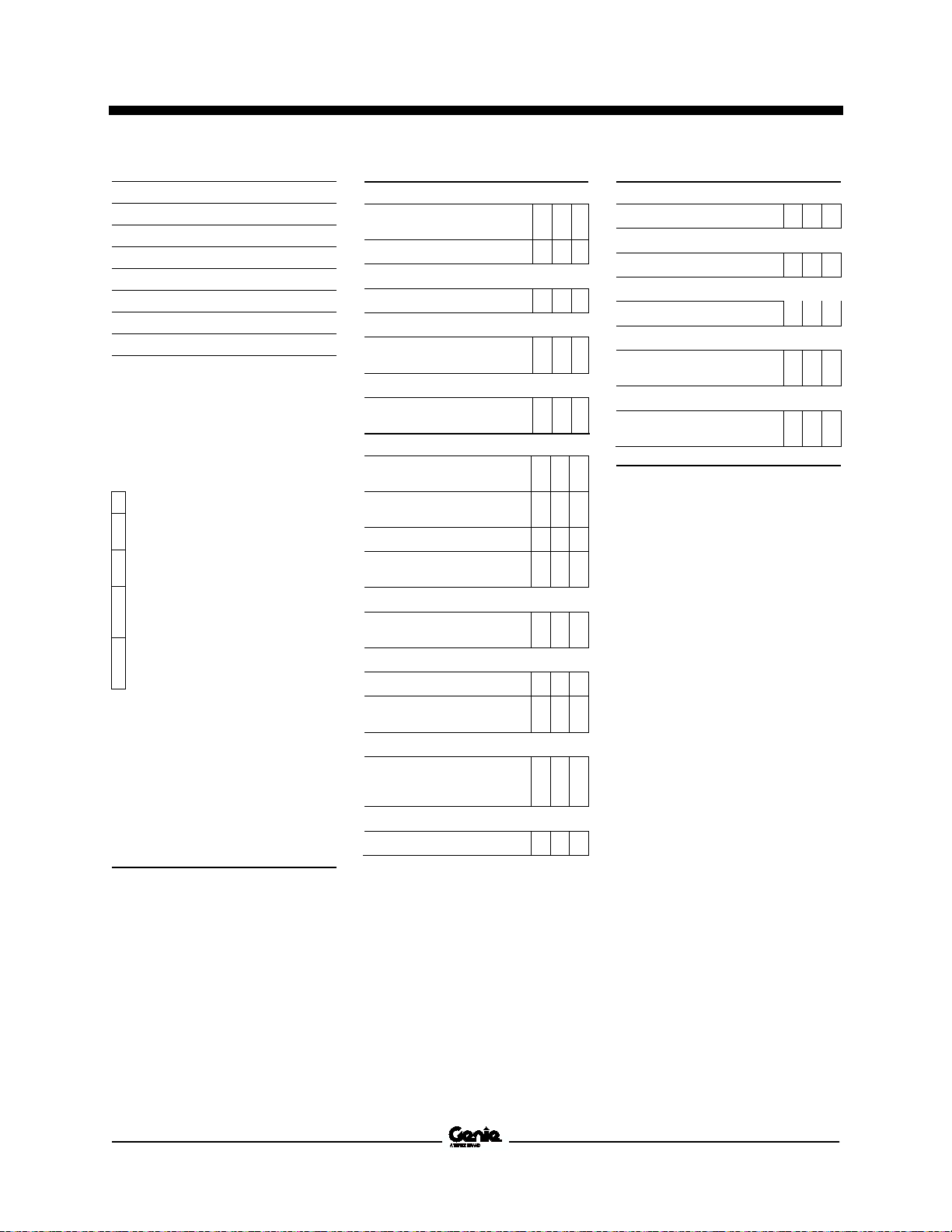
Maintenance Inspection Report
The maintenance inspection report contains
checklists for each type of scheduled inspection.
Make copies of the Maintenance Inspection Report
to use for each inspection. Maintain completed
forms for a minimum of 4 years or in compliance
with your employer, jobsite and governmental
regulations and requirements.
Part No. 1265482 AL5HT 11
Service Manual May 2015
Legend
Comments
Pre
Pre
Maintenance items completed
Function tests completed
Model
Serial number
Date
Machine owner
Inspected by (print)
Inspector signature
Inspector title
Inspector company
Pre-Delivery Preparation Report
Fundamentals
It is the responsibility of the owner or dealer to
perform the Pre-deliver y Pr eparation.
The Pre-delivery Preparation is performed prior to
each delivery. The inspection is designed to
discover if anything is apparently wrong with a
machine before it is put into service.
A damaged or modified machine must never be
used. If damage or any variation from factory
delivered condition is discovered, the machine
must be tagged and removed from service.
Repairs to the machine may only be made by a
qualified service technician, according to the
manufacturer's specifications.
Scheduled maintenance inspections shall be
performed by qualified service technicians,
according to the manufacturer's specifications and
the requirements listed in the responsibilities
manual.
Instructions
Use the operator’s manual on your machine.
The Pre-delivery Preparation consists of
completing the Pre-operation Inspection, the
Maintenance items and the Function Tests.
Use this form to record the results. Place a check in
the appropriate box after each part is completed.
Follow the instructions in the operator’s manual.
If any inspection receives an N, remove the
machine from service, repair and re-inspect it. After
repair, place a check in the R box.
Y = yes, acceptable
N = no, remove from service
R = repaired
-delivery Preparation
-operation inspection c om plete d
Y N R
May 2015 Service Manual
Model
Serial number
Date
Hour meter
Machine owner
Inspected by (print)
Inspector signature
Inspector title
Inspector company
Daily or every
Quarterly or every
25
Semi
every 50
Annually or
every
100
Two
every
200
Legend
Comments
Maintenance Inspection Report
Instructions
• Make copies of this report to use for
each inspection.
• Select the appropriate checklist(s) for
the type of inspection(s) to perform.
0 hours
-annually or
0 hours
-year or
0 hours
• Place a check in the appropriate box
after each inspection procedure is
completed.
• Us e t he step-by-step procedures in
this section to learn how to perform
these inspections.
• I f any inspect i on receives an "N," tag
and remove the machine from service,
repair and re-inspect it. After repair,
place a check in the "R" box.
Y = yes, acceptable
N = no, remove from service
R = repaired
8 hours A
A + B
A + B + C
0 hours
A + B + C + D
A + B + C + D + E
Checklist A Y N R
A-1 Inspect the manuals
and decals
A-2 Pre-operation
inspection
A-3 Function tests
Perform after 8 hours:
A-4 Engine maintenance
A-5 Generator
maintenance
Perform after 10 miles:
A-6 Axle maintenance
Perform after 25 miles:
A-6 Axle maintenance
Perform after 50 miles:
A-6 Axle maintenance
Perform after 40 hours:
A-7 30-day service
Perform after 50 hours:
A-8 Engine maintenance
Perform weekly:
A-9 Coupler
Perform after 100 hours:
A-10 Grease turntable
bearing
A-11 Engine maintenance
- Kubota models
Perform after 200 hours:
A-12 Engine maintenance
- Kubota models
Checklist B Y N R
B-1 Batteries
B-2 Electrical wiring
B-3 Lug nuts
B-4 Hydraulic oil analysis
B-5 Engine maintenance
B-6 Engine maintenance
- Kubota models
B-7 Generator
maintenance
Perform quarterly:
B-8 Coupler
Perform every 400 hours:
B-9 Engine maintenance
- Kubota models
Perform every 3000 miles:
B-10 Axle maintenance
Part No. 1265482 AL5HT 13
Service Manual May 2015
Model
Serial number
Date
Hour meter
Machine owner
Inspected by (print)
Inspector signature
Inspector title
Inspector company
Daily or every
Quarterly or every
25
Semi
every 50
Annually or
every
100
Two
every
200
Legend
Checklist D
Y N R
Checklist E
Comments
Maintenance Inspection Report
Instructions
• Make copies of this report to use for
each inspection.
• Select the appropriate checklist(s) for
the type of inspection(s) to perform.
0 hours
-annually or
0 hours
-year or
0 hours
• Place a check in the appropriate box
after each inspection procedure is
completed.
• Us e t he step-by-step procedures in
this section to learn how to perform
these inspections.
• I f any inspect i on receives an "N," tag
and remove the machine from service,
repair and re-inspect it. After repair,
place a check in the "R" box.
Y = yes, acceptable
N = no, remove from service
R = repaired
8 hours A
A + B
A + B + C
0 hours
A + B + C + D
A + B + C + D + E
Checklist C Y N R
C-1 Inspect tower
extend/retract cables
C-2 Engine maintenance
Perform every 6000 miles:
C-3 Axle maintenance
Perform after 750 hours:
C-4 Engine maintenance -
Isuzu models
Perform every 800 hours:
C-5 Engine maintenance -
Kubota models
D-1 Engine maintenance
- Kubota models
D-2 Generator
maintenance
D-3 Hydraulic filters
D-4 Engine maintenance
- Isuzu models
Perform every 1250 hours:
D-5 Engine maintenance
- Isuzu models
Perform every 1500 hours:
D-6 Engine maintenance
D-7 Generator
maintenance
Perform annually:
D-8 Tongue jack and
outrigger jack
maintenance
Perform every 12,000 hours:
D-9 Axle maintenance
Y N R
E-1 Hydraulic oil analysis
Perform every 3000 hours:
E-2 Engine maintenance
Perform every 2 years:
E-3 Engine maintenance
Perform every 4500 hours:
E-4 Generator
maintenance
Perform every 15,000 hours:
E-5 Generator
maintenance
14 AL5HT Part No. 1265482

May 2015 Service Manual
Checklist A Procedures
A-1 Inspect the Manuals and Decal s
Terex specifications require that this procedure be
performed every 8 hours or daily, whichever comes
first.
Maintaining the operator’s and safety manuals in
good condition is essential to safe machine
operation. Manuals are included with each
machine and should be stored in the container
provided in the platform. An illegible or missing
manual will not provide safety and operational
information necessary for a safe operating
condition.
In addition, maintaining all of the safety and
instructional decals in good condition is mandatory
for safe machine operation. Decals alert operators
and personnel to the many possible hazards
associated with using this machine. They also
provide users with operation and maintenance
information. An illegible decal will fail to alert
personnel of a procedure or hazard and could
result in unsafe operating conditions.
3 Open the operator's manual to the decals
inspection section. Carefully and thoroughly
inspect all decals on the machine for legibility
and damage.
Result: The machine is equipped with all
required decals, and all decals are legible and
in good condition.
Result: The machine is not equi ppe d with al l
required decals, or one or more decals are
illegible or in poor condition. Remove the
machine from service until the decals are
replaced.
4 Always return the manuals to the storage
container after use.
Note: Contact your authorized Terex distributor or
Terex if replacement manuals or decals are
needed.
1 Check to make sure that the operator's and
safety manuals are present and complete in
the storage container inside the cabinet.
2 Examine the pages of each manual to be sure
that they are legible and in good condition.
Result: The operator's manual is appropriate
for the machine and all manuals are legible
and in good condition.
Result: The operator's manual is not
appropriate for the machine or all manuals are
not in good condition or is illegible. Remove
the machine from service until the manual is
replaced.
Part No. 1265482 AL5HT 15
Service Manual May 2015
Checklist A Procedures
A-2 Perform Pre-operation Inspection
Terex specifications require that this procedure be
performed every 8 hours or daily, whichever comes
first.
Completing a Pre-operation Inspection is essential
to safe machine operation. The Pre-operation
Inspection is a visual inspection performed by the
operator prior to each work shift. The inspection is
designed to discover if anything is apparently
wrong with a machine before the operator performs
the function tests. The Pre-operation Inspection
also serves to determine if routine maintenance
procedures are required.
Complete information to perform this procedure is
available in the appropriate operator's manual.
Refer to the Operator's Manual on your machine.
A-3 Perform Function Tests
Terex specifications require that this procedure be
performed every 8 hours or daily, whichever comes
first.
Completing the function tests is essential to safe
machine operation. Function tests are designed to
discover any malfunctions before the machine is
put into service. A malfunctioning machine must
never be used. If malfunctions are discovered, the
machine must be tagged and removed from
service.
Complete information to perform this procedure is
available in the appropriate operator's manual.
Refer to the Operator's Manual on your machine.
16 AL5HT Part No. 1265482
May 2015 Service Manual
Isuzu 4LE1 Diesel Engine Owner's Manual
Genie part number 116133
Isuzu 4LE2 Diesel Engine Owner's Manual
Genie part number 1264609
Kubota D-1105 and V-1505 Operator's Manual
Genie part number 893020
Marathon Manual
Genie part number 116188
Checklist A Procedures
A-4 Perform Engine Maintenance
Engine specifications require that this procedure be
performed every 8 hours or daily, whichever comes
first.
• Engine oil level – check
• Coolant level – check/add
• Fuel system filter/water separator – drain
• Engine tightness – check for leaks
• Exhaust system – check for leaks
• Loose or missing fasteners
Required maintenance procedures and additional
engine information is available in the Ku bota
D1105-E and V1505-E Operator's Manual (Kubota
16683-89169 part number ) OR the Isuzu 4LE1
Diesel Engine Owner's Manual (Isuzu part number
IDE-6033) OR the Isuzu 4LE2 Diesel Engine
Owner's Manual (Isuzu part number IDE-6450).
A-5 Perform Generator Maintenance
Generator specifications require that this
procedure be performed every 40 hours or weekly,
whichever comes first.
• Clean and inspect the generator exterior
• Clean and replace the generator air filters -
(if equipped)
Part No. 1265482 AL5HT 17

Service Manual May 2015
Checklist A Procedures
A-6 Perform Axle Maintenance
Axle specifications require that this procedure be
performed initially and following a wheel change
after the first 10, 25 and 50 miles.
Proper axle maintenance, following the axle
manufacturer's maintenance schedule, is essential
to good axle performance and service life. Failure
to perform the maintenance procedures can lead to
poor axle performance and component damage.
Required maintenance procedures and additional
axle information is available in the Axis Axle
Operator Maintenance Manual included with your
machine.
A-7 Torque the Wheel Lug Nuts
Axle specifications require that this procedure be
performed initially at 10, 25 and 50 miles of use, or
after reinstallation of a tire.
Maintaining the wheel lug nuts at proper torque is
essential to safe operation and good service life of
the tires, wheel and axle.
1 Check each lug nut for proper torque. Refer to
Specifications, Machine Specifications.
18 AL5HT Part No. 1265482
May 2015 Service Manual
Isuzu 4LE1 Diesel Engine Owner's Manual
Genie part number 116133
Isuzu 4LE2 Diesel Engine Owner's Manual
Genie part number 1264609
Kubota D-1105 and V-1505 Operator's Manual
Genie part number 893020
Checklist A Procedures
A-8 Perform Engine Maintenance
Engine specifications require that this procedure be
performed every 50 hours or weekly, whichever
comes first.
Required maintenance procedures and additional
engine information is available in the Ku bota
D1105-E and V1505-E Operator's Manual (Kubota
16683-89169 part number ) OR the Isuzu 4LE1
Diesel Engine Owner's Manual (Isuzu part number
IDE-6033) OR the Isuzu 4LE2 Diesel Engine
Owner's Manual (Isuzu part number IDE-6450).
A-9 Perform Coupler Maintenance
Coupler specifications require that this procedure
be performed weekly.
Maintaining the coupler in good condition is
essential to safe operation and good performance.
Coupler failure could result in a machine tip-over
during transport, and component damage may also
result if problems are not discovered and repaired
in a timely fashion.
1 Check coupler welds and mounting bolt
torque. Torque the fasteners to 35 ft-lbs / 48
Nm.
Result: 1.5 full threads of the locking bolt must
be exposed beyond the lock nut after the
adjustment.
2 Apply automotive grease to the coupler ball
pocket.
3 Oil coupler pivot points using SAE 30 motor
oil.
Part No. 1265482 AL5HT 19
 Loading...