

Terex BT4792 User Manual
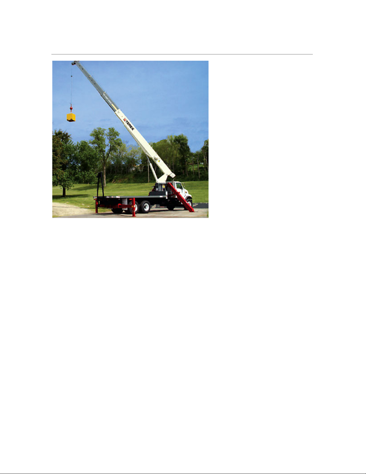
Terex BT4792 Boom Truck
Maximum Boom Length: 92 ft (28.0 m)
Number of Boom Sections: 4
Available Jib Length: 44 ft (13.41 m)
Maximum Tip Height with Jib: 144 ft (43.90 m)
Swing 1 Rotation (sec): 75
Boom up / down (sec): 41/30
Boom Extension / Retract
(sec):
80/36
Chassis: 2004 Sterling LT7501
Combined Axle Weight: 60,000 Ib (27 210 kg)
Front Axle Weight: 20,000 Ib (9 067 kg)
Rear Axle Weight: 40,000 Ib (18 144 kg)
Standard Engine Type: Caterpillar C-7 7.2L I-6
Standard Horsepower: 300 hp @ 2,200 rpm
Engine Transmissions: Eaton Fuller RT-8908LL
Overall Length: 38 ft (5.14 m)
Overall Width: 8 ft (2.44 m)
Overall Height: 13 ft 2 in (4.1 m)
Weight Crane + Vehicle:
(Assumes Std Chassis)
W
eight Crane Only: 25,172 lb (11 418 kg)
41,732 lb (18 929 kg)
STINGER 4792
|
Boom Truck Crane
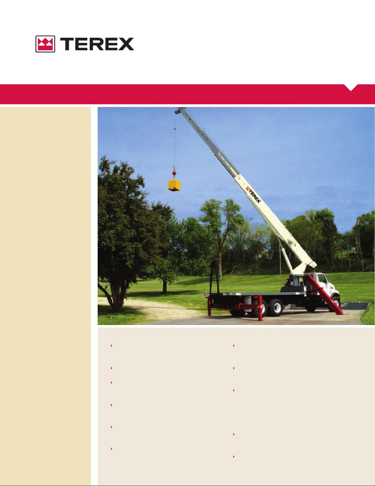
STINGER 4792
BOOM TRUCK CRANE
FEATURES
47,000 Ib (21 319 kg) maximum lifting
capacity
101’ (30.78 m) maximum sheave height
144’ (43.89 m) maximum sheave height
with 26-44’ (7.92-13.41 m) jib
29-92’ (8.84-28.04 m) four-section full
power fully synchronized boom
Exclusive color coded boom and load
charts
Easy-to-install optional 26’ (7.92 m) one
stage or 26-44’ (7.92-13.41 m) two
stage telescoping jib, man baskets or
work platform increase job capacities
Electronic Load Moment Indicator and
anti-two-block device standard
Externally located planetary rotation drive
for easy accessibility for maintenance
2-speed planetary winch has 10,500 lb
(4 703 kg) maximum permissible 1 part
line, 37,000 Ib (16 783 kg) breaking
strength, 186 ft/min (57 m/min) maximum line speed
Dual control station with direct mechanically controlled hydraulic system
90 gal (342 L) capacity hydraulic tank
GENERAL NOTES
JIB CAPACITIES FOR ALL BOOM LENGTHS
Loaded Boom Angle
Retracted 26 ft Jib
Extended 44 ft Jib
VERIFY OPERATIONAL MODE SETTING ON LMI DISPLAY BEFORE LIFTING WITH JIB
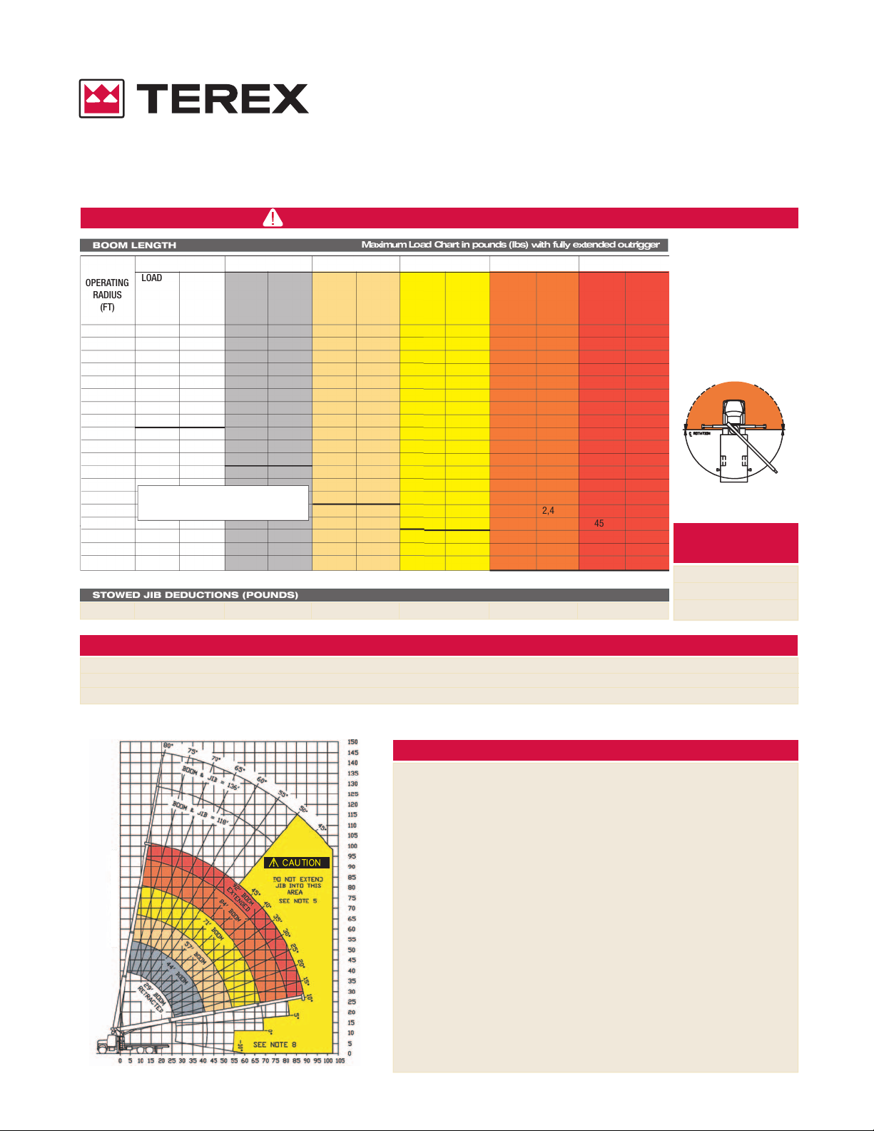
RANGE DIAGRAM (29 - 92 FT BOOM)
SHEAVE HEIGHT - FEET
Max
imum Load Chart in pounds (lbs) with fully extended outrigger
BOOM LENGTH
STOWED JIB DEDUCTIONS (POUNDS)
OPERA
TING
RADIUS
(FT)
LOA
DED
BOOM
ANGLE
(DEG)
29 FT 44 FT 57 FT 71 FT 84 FT
LOA
D
RAT
ING
(LB)
LOA
DED
BOOM
ANGLE
(DEG)
LOA
D
RAT
ING
(LB)
LOA
DED
BOOM
ANGLE
(DEG)
LOA
D
RAT
ING
(LB)
LOA
DED
BOOM
ANGLE
(DEG)
LOA
D
RAT
ING
(LB)
LOA
DED
BOOM
ANGLE
(DEG)
LOA
D
RAT
ING
(LB)
92 FT
LOA
DED
BOOM
ANGLE
(DEG)
LOA
D
RAT
ING
(LB)
700 500 350 300 250 200
50º 55º 60º 65º 70º 75º 78º 80º
725 1,025 1,525 2,325 3,225 4,325 4,925 5,325
425 725 1,125 1,525 2,025 2,525 2,825 3,125
STINGER
4792
BOO
M TRUCK CRANE
5
78 47,000*
8
71 36,800* 78 20,300*
10
67 30,900* 75 20,300* 79 18,400*
12 62 26,100* 73 20,300* 77 17,400*
14 58 21,900* 70 19,400* 75 16,800* 78 14,600*
16 53 18,800* 67 17,300* 73 15,900* 77 13,800* 79 12,300*
20 41 14,200* 61 13,900* 68 13,400* 73 12,300* 76 10,900* 78 9,825*
25 21 10,400* 53 10,900* 63 10,600* 69 10,400* 73 9,800* 75 9,025*
30 45 8,625* 57 8,625* 65 8,425* 69 8,225* 71 7,425*
35 34 6,925* 51 6,925* 60 6,925* 66 6,725* 68 6,325*
40 19 5,225* 44 5,625* 56 5,625* 62 5,625* 65 5,425*
45
36 4,625* 50 4,625* 58 4,625* 61 4,625*
50
26 3,725* 45 3,725* 53 3,725* 57 3,725*
55 1 1,225* 38 3,025* 49 3,025* 53 3,025*
60 31 2,425* 44 2,425* 49 2,425*
65 21 2,025* 39 2,025* 45 2,025*
70 32 1,525* 40 1,525*
75 25 1,225* 35 1,225*
80 14 825* 28 825*
Dedu
ctions from rate
loads for load handling
devic
es BT
Overhaul Bal
l 175 lbs
1 Sheave Load Block 200 lbs
2 Sheave Load Block 250 lbs
NOTE: STRUCTURAL STRENGTH RATINGS IN
CHART ARE INDICATED WIH AN ASTERISK *
LOAD RATINGS
BT MODEL
CAUTION Do not use this specification sheet as a load rating chart. The format of data
is not consistent with the machine chart and may be subject to change.
AREA OF OPERATION
DO NOT OPERATE
IN SHADED AREA
WITHOUT
OPTIONAL FRONT
STAB
ILIZER
CENTERLINE OF ROTATION
1. The operator must read and understand the Owner's Manual before operating this crane.
2. Positioning or operation of crane beyond areas shown on this chart is not intended or approved except where
specified in Owner's Manual.
3. Loaded boom angles at specified boom lengths give only an approximation of the operating radius. The boom angle
before loading should be greater to account for deflections. Do not exceed the operating radius for rated loads.
4. Use rating of next longer boom for boom lengths not shown. Use rating of next greater radius for load radii not shown.
5. Boom must be fully retracted when jib is erected before lowering below minimum angle. Retracted jib has no lifting
capacity below a 50° boom angle.
6. Use rating of next lower boom angle for boom angles not shown on jib load rating chart.
7. Lifting off the main boom point while the swing around jib is erected is not intended or approved.
8. Do not lower boom into this area, as hydraulic pressure will not allow raising the boom without retracting boom first.
9. Crane load ratings on outriggers are based on freely suspended loads with the machine leveled and standing on a firm
uniform supporting surface. No attempt shall be made to move a load horizontally on the ground in any direction.
10. Practical working loads depend on supporting surface, wind and other factors affecting stability such as hazardous
surroundings, experience of personnel, and proper handling, must all be taken into account by the operator.
11. The maximum load which may be telescoped is limited by hydraulic pressure, boom angle, and boom lubrication. It is
safe to attempt to telescope any load within the limits of the load rating chart.
INFORMATION
1. Deductions must be made from rated loads for stowed jib, optional attachments, hooks and loadblocks (see deduction
chart). Weights of slings and other load handling devices shall be considered a part of the load.
2. Crane load ratings with outriggers are based on outriggers and stabilizers extended and set with all load removed
from the carrier wheels.
3. Load ratings do not exceed 85% of tipping load.
DEFINITIONS
1. Operating radius is the horizontal distance from the axis of rotation to the center of the vertical hoist line or load hook
with load suspended.
2. Loaded boom angle as shown in the Load Ratings Chart is the included angle between the horizontal and longitudinal
axes of the boom base after lifting rated load at rated radius.
 Loading...