

Terex AL8000HT Service Manual
Service Manual
TM
AL8000HT
First Edition
Rev A
Part No. 116478
September 2008
Introduction
Important
Read, understand and obey the safety rules and
operating instructions in the appropriate Operator's
Manual on your machine before attempting any
maintenance procedure.
Basic mechanical, hydraulic and electrical
skills are required to perform most procedures.
However, several procedures require specialized
skills, tools, lifting equipment and a suitable
workshop. In these instances, we strongly
recommend that maintenance and repair be
performed at an authorized Terex dealer
service center.
September 2008
Technical Publications
Terex has endeavored to deliver the highest degree
of accuracy possible. However, continuous
improvement of our products is a Terex policy.
Therefore, product specifications are subject to
change without notice.
Readers are encouraged to notify Terex of errors
and send in suggestions for improvement. All
communications will be carefully considered for
future printings of this and all other manuals.
Contact Us:
Internet: www.genielift.com
e-mail: techpub@genieind.com
Copyright © 2008 by Terex
Terex Rock Hill
590 Huey Road
Rock Hill, SC. 29730
116478 Rev A September 2008
First Edition, First Printing
" Printed on recycled paper
Printed in U.S.A.
ii
AL8000HT Light Tower Part No. 116478
September 2008
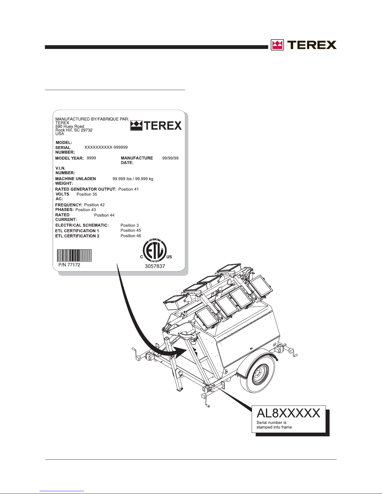
How to Read Your Serial Number
Serial Number Legend
Part No. 116478 AL8000HT Light Tower
iii
Section 1 • Safety Rules September 2008
Safety Rules
Danger
Failure to obey the instructions and safety rules
in this manual and the
Manual
serious injury.
Many of the hazards identified in the operator’s
manual are also safety hazards when maintenance
and repair procedures are performed.
on your machine will result in death or
Terex AL8000HT Operator's
Do Not Perform Maintenance
Unless:
You are trained and qualified to perform
maintenance on this machine.
You read, understand and obey:
- manufacturer’s instructions and safety rules
- employer’s safety rules and worksite
regulations
- applicable governmental regulations
You have the appropriate tools, lifting
equipment and a suitable workshop.
iv
AL8000HT Light Tower Part No. 116478
Section 1 • Safety RulesSeptember 2008
SAFETY RULES
Personal Safety
Any person working on or around a machine must
be aware of all known safety hazards. Personal
safety and the continued safe operation of the
machine should be your top priority.
Read each procedure thoroughly. This
manual and the decals on the machine,
use signal words to identify the following:
Safety alert symbol—used to alert
personnel to potential personal
injury hazards. Obey all safety
messages that follow this symbol
to avoid possible injury or death.
Indicates an imminently hazardous
situation which, if not avoided, will
result in death or serious injury.
Indicates a potentially hazardous
situation which, if not avoided,
could result in death or serious
injury.
Indicates a potentially hazardous
situation which, if not avoided,
may cause minor or moderate
injury.
Workplace Safety
Be sure to keep sparks, flames and
lighted tobacco away from flammable and
combustible materials like battery gases
and engine fuels. Always have an approved fire
extinguisher within easy reach.
Be sure that all tools and working areas
are properly maintained and ready for use.
Keep work surfaces clean and free of
debris that could get into machine components and
cause damage.
Be sure any forklift, overhead crane or
other lifting or supporting device is fully
capable of supporting and stabilizing the
weight to be lifted. Use only chains or straps that
are in good condition and of ample capacity.
Be sure that fasteners intended for one
time use (i.e., cotter pins and self-locking
nuts) are not reused. These components
may fail if they are used a second time.
Be sure to properly dispose of old oil or
other fluids. Use an approved container.
Please be environmentally safe .
Be sure that your workshop or work area is
properly ventilated and well lit.
Indicates a potentially hazardous
situation which, if not avoided,
may result in property damage.
Be sure to wear protective eye wear and
other protective clothing if the situation
warrants it.
Be aware of potential crushing hazards
such as moving parts, free swinging or
unsecured components when lifting or
placing loads. Always wear approved steel-toed
shoes.
Part No. 116478 AL8000HT Light Tower
v

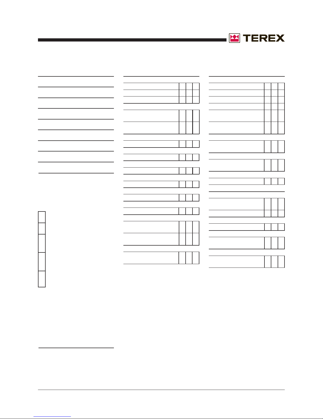
Table of Contents
Introduction
September 2008
Important Information ...........................................................................................................
How to Read Your Serial Number ........................................................................................
Parts Stocking List .............................................................................................................
How to Order Parts .............................................................................................................
Service Parts Fax Order Form ...........................................................................................
Section 1 Safety Rules
General Safety Rules ..................................................................................................
Section 2 Rev Specifications
A Machine Specifications .......................................................................................... 2 - 1
Performance Specifications ................................................................................... 2 - 1
Hydraulic Oil Specifications ................................................................................... 2 - 2
Hydraulic Component Specifications ...................................................................... 2 - 2
Manifold Component Specifications ....................................................................... 2 - 3
Kubota D1105-E Engine ......................................................................................... 2 - 4
Kubota V1505-E Engine ........................................................................................ 2 - 5
ii
iii
x
xi
xii
iv
Isuzu 4LE1 Engine................................................................................................. 2 - 6
Generator Specifications ........................................................................................ 2 - 7
Hydraulic Hose and Fitting Torque Specifications .................................................. 2 - 8
SAE and Metric Fasteners Torque Charts .............................................................. 2 - 9
Genset Torque Specifications .............................................................................. 2 - 10
Section 3 Rev Scheduled Maintenance Procedures
Introduction ............................................................................................................ 3 - 1
Pre-delivery Preparation Report .............................................................................. 3 - 3
Maintenance Inspection Report .............................................................................. 3 - 5
A Checklist A Procedures
A-1 Inspect the Manuals and Decals .................................................................. 3 - 7
A-2 Perform Pre-operation Inspection ................................................................. 3 - 8
A-3 Perform Function Tests ................................................................................ 3 - 8
vi
AL8000HT Light Tower Part No. 116478

September 2008
A-4 Perform Engine Maintenance - Isuzu Models ............................................... 3 - 9
Section 3 Rev Scheduled Maintenance Procedures, continued
A-5 Perform Generator Maintenance ................................................................... 3 - 9
A-6 Perform Axle Maintenance ......................................................................... 3 - 10
A-7 Perform 30 Day Service ............................................................................. 3 - 10
A-8 Perform Engine Maintenance ..................................................................... 3 - 11
A-9 Perform Hitch Maintenance ........................................................................ 3 - 11
A-10 Grease the Turntable RotationBearing and Rotate Gear ............................. 3 - 12
A-11 Perform Engine Maintenance - Kubota Models ........................................... 3 - 13
A-12 Perform Engine Maintenance - Kubota Models ........................................... 3 - 13
A Checklist B Procedures
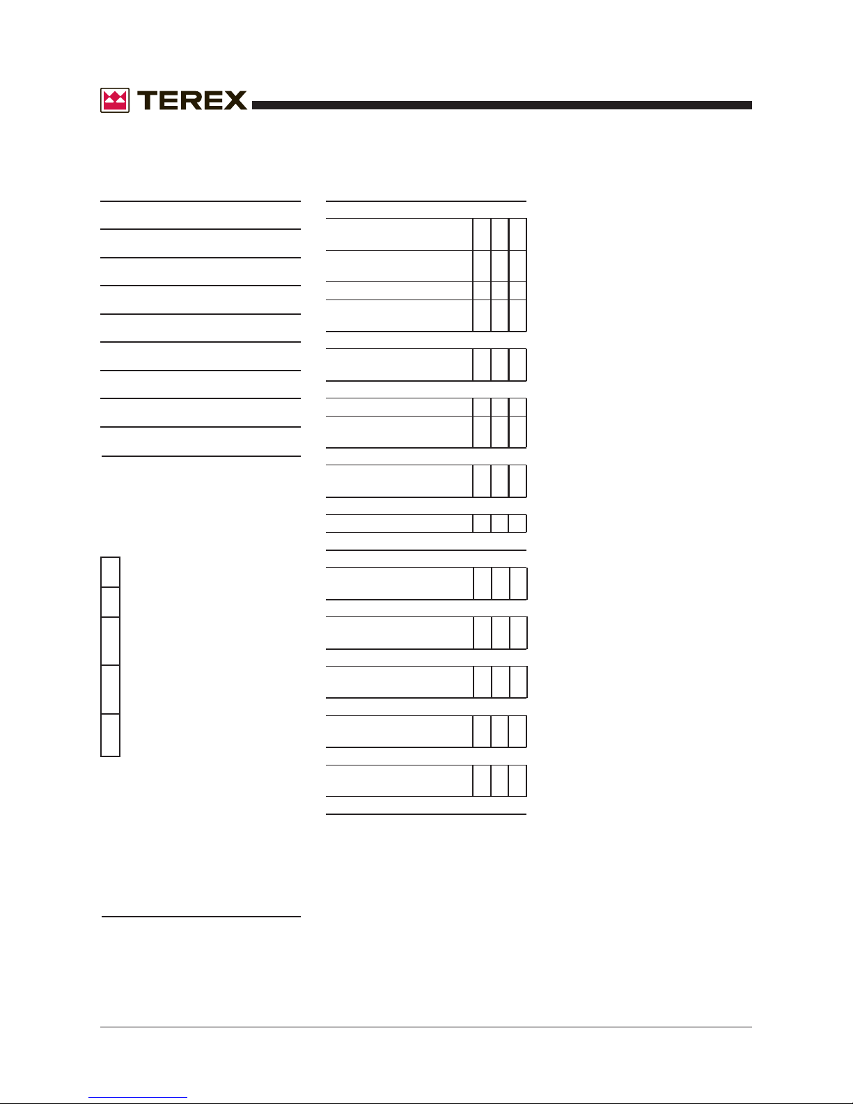
TABLE OF CONTENTS
B-1 Inspect the Battery ..................................................................................... 3 - 14
B-2 Inspect the Electrical Wiring ....................................................................... 3 - 14
B-3 Inspect the Tires and Wheels (including lug nut torque) .............................. 3 - 15
B-4 Perform Hydraulic Oil Analysis ................................................................... 3 - 15
B-5 Perform Engine Maintenance - Isuzu Models ............................................. 3 - 16
B-6 Perform Generator Maintenance ................................................................. 3 - 16
B-7 Perform Hitch Maintenance ........................................................................ 3 - 17
B-8 Perform Engine Maintenance - Kubota Models ........................................... 3 - 17
B-9 Perform Axle Maintenance ......................................................................... 3 - 17
A Checklist C Procedures
C-1 Inspect the Tower Extend/Retract Cables and Pulleys ............................... 3 - 19
C-2 Perform Engine Maintenance ..................................................................... 3 - 19
C-3 Perform Axle Maintenance ......................................................................... 3 - 20
C-4 Perform Engine Maintenance - Isuzu Models ............................................. 3 - 20
C-5 Perform Engine Maintenance - Kubota Models ........................................... 3 - 21
A Checklist D Procedures
D-1 Perform Engine Maintenance - Kubota Models ........................................... 3 - 22
D-2 Check the Tower Rotation Bearing Bolts .................................................... 3 - 22
D-3 Replace the Hydraulic Return Filter ............................................................ 3 - 23
D-4 Perform Engine Maintenance - Isuzu Models ............................................. 3 - 24
Part No. 116478 AL8000HT Light Tower
vii

TABLE OF CONTENTS
D-5 Perform Engine Maintenance - Isuzu Models ............................................. 3 - 24
D-6 Perform Engine Maintenance ..................................................................... 3 - 25
Section 3 Rev Scheduled Maintenance Procedures, continued
D-7 Perform Generator Maintenance ................................................................. 3 - 25
D-8 Perform Tongue Jack and Outrigger Jack Maintenance ............................. 3 - 26
D-9 Perform Axle Maintenance ......................................................................... 3 - 26
E-1 Test or Replace the Hydraulic Oil ............................................................... 3 - 27
E-2 Perform Engine Maintenance - Kubota Models ........................................... 3 - 28
E-3 Perform Engine Maintenance - Kubota Models ........................................... 3 - 29
E-4 Perform Generator Maintenance ................................................................. 3 - 29
E-5 Perform Generator Maintenance ................................................................. 3 - 30
September 2008
Section 4 Rev Repair Procedures
Introduction ............................................................................................................ 4 - 1
A Lighting
1-1 Lighting ........................................................................................................ 4 - 2
A Light Bar Components
2-1 Light Bar ...................................................................................................... 4 - 4
2-2 Light Bar Lift Cylinder ................................................................................... 4 - 5
A Tower Components
3-1 Plastic Cable Track ...................................................................................... 4 - 7
3-2 Tower Assembly .......................................................................................... 4 - 7
3-3 Tower Lift Cylinder ..................................................................................... 4 - 10
3-4 Tower Extension Cylinder ........................................................................... 4 - 11
3-5 Tower Rotation Motor ................................................................................. 4 - 12
A Kubota D1105-E/V1505-E Engine
4-1 Timing Adjustment ..................................................................................... 4 - 13
4-2 Glow Plugs ................................................................................................. 4 - 13
4-3 Coolant Temperature and Oil Pressure Switches ........................................ 4 - 13
A Isuzu 4LE1 Engine
5-1 Timing Adjustment ..................................................................................... 4 - 14
viii
AL8000HT Light Tower Part No. 116478

September 2008
TABLE OF CONTENTS
5-2 Glow Plugs ................................................................................................. 4 - 14
5-3 Coolant Temperature and Oil Pressure Switches ........................................ 4 - 14
Section 4 Rev Repair Procedures, continued
A Generator
6-1 Generator ................................................................................................... 4 - 15
A Chassis Components
7-1 Ground Controls ......................................................................................... 4 - 19
7-2 Light Ballast ............................................................................................... 4 - 20
7-3 Fuel Tank ................................................................................................... 4 - 21
8-1 Function Manifold Components .................................................................. 4 - 23
8-2 Valve Adjustments - Function Manifold ...................................................... 4 - 24
Section 5 Rev Troubleshooting
Introduction ............................................................................................................ 5 - 1
A Troubleshooting Guide ........................................................................................... 5 - 2
A Light Fixture Troubleshooting ................................................................................. 5 - 5
Section 6 Rev Schematics
A Introduction ............................................................................................................ 6 - 1
A Electrical Symbols Legend .................................................................................... 6 - 2
A Hydraulic Symbols Legend .................................................................................... 6 - 3
A Electrical Schematic - Machine Functions ............................................................. 6 - 4
A DC Electrical Schematic - Control Box and Engine - Isuzu Models ....................... 6 - 5
A DC Electrical Schematic - Control Box and Engine - Kubota Models .................... 6 - 6
A DC Electrical Schematic - Control Box and Engine - with Autostart Option ........... 6 - 7
A AC Electrical Schematic - Standard Models with 4 Lights ...................................... 6 - 8
A AC Electrical Schematic - Standard Models with 6 Lights ...................................... 6 - 9
A AC Electrical Schematic - Standard Models with 8 Lights .................................... 6 - 10
A AC Electrical Schematic - Autostart Models with 4 Lights .................................... 6 - 11
A AC Electrical Schematic - Autostart Models with 6 Lights .................................... 6 - 12
A AC Electrical Schematic - Autostart Models with 8 Lights .................................... 6 - 13
A Receptacle Wiring Diagrams ................................................................................ 6 - 14
A Hydraulic Schematic ............................................................................................ 6 - 15
Part No. 116478 AL8000HT Light Tower
ix
Parts Stocking List
Required Parts
The following parts are required to perform
maintenance procedures as outlined in the
TEREX AL8000HT Parts and Service Manual.
Description Part No.
Kubota Models
Oil Filter .............................................................. 866050
Air Filter .............................................................. 866127
Fuel Filter ........................................................... 839200
V-belt ................................................................. 839209
Isuzu Models
Oil Filter .............................................................. 868075
Air Filter .............................................................. 834460
Fuel Filter ........................................................... 868137
V-belt ................................................................. 868067
September 2008
Manuals
TEREX Corporation offers the following manuals for
these models:
Title Part No.
TEREX AL8000HT Operator's Manual, .............. 114426
First Edition
TEREX AL8000HT Part's Manual, ..................... 116447
First Edition
TEREX AL8000HT Service Manual, ..................116478
First Edition
Newage Generator Manual ................................ 830001
Leroy Somer Manual .......................................... 116118
Isuzu Engine Manual ......................................... 116133
Kubota Engine Manual ....................................... 893020
Axis Manual ........................................................ 116117
Marathon Manual ............................................... 116188
x
AL8000HT Light Tower Part No. 116478
September 2008
How To Order Parts
Please be prepared with the following information
when ordering replacement parts for your TEREX
product:
Machine model number
Machine serial number
Terex part number
Part description and quantity
Purchase order number
"Ship to" address
Desired method of shipment
Name and telephone number of the
authorized TEREX Distributor in your area
Use the Service Parts Fax Order Form on the
next page and fax your order to our Parts
Department.
If you don't know the name of your authorized
distributor, or if your area is not currently serviced
by an authorized distributor, please call TEREX
Corporation.
Machine Information
Genie Industries
18340 NE 76th Street
P.O. Box 97030
Redmond, WA 98073-9730
Telephone (877) 367-5606
Fax (888) 274-6192
genieindustries.com
Model
Serial Number
Date of Purchase
Authorized TEREX Distributor
Phone Number
Part No. 116478 AL8000HT Light Tower
xi
September 2008
Service Parts fax Order Form
Please fill out completely
Date _________________________________ Account Number _______________________________
Your Name ______________________________ Your Fax Number _____________________________
_________________________________ Your Phone Number ___________________________
Bill To _________________________________ Ship To ___________________________________
_________________________________ ___________________________________
_________________________________ ___________________________________
_________________________________ ___________________________________
Purchase Order Number ____________________ Ship Via ___________________________________
Model(s) ______________________________________________________ Serial No.(s) _________________
FAX TO: (888) 274-6192 OR TOLL FREE: 877-367-5606
Optional Equipment ___________________________________________________________________________
Part Number Description Quantity Price
remove this page and make copies
All backordered parts will be shipped when available via the same ship method as the original order unless
noted below:
o Ship complete order only - no backorders
o Ship all available parts and contact customer on disposition of backordered parts
o Other (please specify)
FOR TEREX USE O NLY
Order Number ______________ Origin Code ________________ Comments _________________________
Date Scheduled ____________ Ship Condition _____________ __________________________________
Order Total ________________ Terms Code _______________ __________________________________
remove this page and make copies
AL8000HT Light Tower Part No. 116478
September 2008
Section 2 • Specifications
REV A
Machine Specifications
Lights
Type: BT-37 Metal Halide, 1000 watt
Total lighting wattage
4 lights 4000 watts
8 lights 8000 watts
Axle
Axle load capacity, maximum 4200 lbs
1905 kg
Fluid capacities
Hydraulic tank capacity 1.4 gallons
5.3 liters
Hydraulic system capacity 2 gallons
(including tank) 7.6 liters
Single fuel tank 30 gallons
114 liters
Dual fuel tanks 60 gallons
227 liters
Tires and wheels (U.S. models)
Tire size ST205/75R15
Load range C
Lug nut torque, dry 80 ft-lbs
108 Nm
Tire pressure, maximum (cold) 50 psi
3.4 bar
Tires and wheels (Australia models)
Tire size 7.5R16 C 112/110L
Lug nut torque, dry 80 ft-lbs
108 Nm
Specifications
Performance Specifications
Tongue weight, maximum 350 lbs
159 kg
Run time, full load
Kubota D1105 (8kW) @ .82 Gallons per hour
Single full fuel tank 36.5 hours
Dual full fuel tanks 73 hours
Run time, full load
Kubota V1505 (12kW) @ 1.1 Gallons per hour
Single full fuel tank 27.25 hours
Dual full fuel tanks 54.5 hours
Run time, full load
Isuzu 4LE1 (20kW) @ 1.8 Gallons per hour
Single full fuel tank 16.5 hours
Dual full fuel tanks 33 hours
Towing speed, maximum 62 mph
100 km/h
Function speeds
Boom up 12 to 24 seconds
Boom down 12 to 21 seconds
Boom extend 17 to 37 seconds
Boom retract 13 to 27 seconds
Light bar up 18 to 30 seconds
Light bar down 14 to 24 seconds
Tower rotate, 359° 31 to 68 seconds
Tire pressure, maximum (cold) 75 psi
For operational specifications, refer to the
Operator's Manual.
Part No. 116478 AL8000HT Light Tower 2 - 1
5.2 bar
Continuous improvement of our products is a
Terex policy. Product specifications are subject
to change without notice.
Section 2 • Specifications
September 2008
SPECIFICATIONS
Hydraulic Oil Specifications
Hydraulic Oil Specifications
Hydraulic oil type Chevron Rando HD Premium MV
Viscosity grade Multi-viscosity
Viscosity index 200
Cleanliness level, minimum 15/13
Water content, maximum 200 ppm
Chevron Rykon MV oil is fully compatible and
mixable with Shell Donax TG (Dexron III) oils.
Genie specifications require hydraulic oils which are
designed to give maximum protection to hydraulic
systems, have the ability to perform over a wide
temperature range, and the viscosity index should
exceed 140. They should provide excellent antiwear,
oxidation, corrosion inhibition, seal conditioning, and
foam and aeration suppression properties.
Optional fluids
Biodegradable Petro Canada Environ MV46
Statoil Hydra Way Bio Pa 32
BP Biohyd SE-S
Fire resistant UCON Hydrolube HP-5046
Quintolubric 822
REV A
Hydraulic Component
Specifications
Function pump
Type: Fixed displacement gear pump
Displacement 0.056 cu in
per revolution 0.92 cc
Flow rate @ 3200 psi 0.6 gpm
2.27 L/min
System relief pressure 3200 psi
220.6 bar
Function manifold
Light bar up/down 0.2 gpm
flow regulator 0.76 L/min
Tower rotate relief 1200 psi
valve pressure 82.7 bar
Hydraulic filter
Hydraulic tank Beta 10 ≥ 200
return filter with 25 psi / 1.7 bar bypass
Mineral based Shell Tellus T32
Shell Tellus T46
Chevron Aviation A
Continued use of Chevron Aviation
A hydraulic fluid when ambient
temperatures are consistently
above 32°F / 0°C may result in
component damage.
Note: Use Chevron Aviation A hydraulic fluid when
ambient temperatures are consistently below
0°F / -18°C.
Note: Use Shell Tellus T46 hydraulic oil when oil
temperatures consistently exceed 205°F / 96°C.
Note: Terex specifications require additional
equipment and special installation instructions for
the approved optional fluids. Consult the Terex
Service Department before use.
Continuous improvement of our products is a
Terex policy. Product specifications are subject
to change without notice.
2 - 2 AL8000HT Light Tower Part No. 116478
September 2008
Section 2 • Specifications
REV A
Manifold Component
Specifications
Plug torque
SAE No. 2 36 in-lbs / 4 Nm
SAE No. 4 10 ft-lbs / 13 Nm
SAE No. 6 14 ft-lbs / 19 Nm
SAE No. 8 38 ft-lbs / 51 Nm
SAE No. 10 41 ft-lbs / 55 Nm
SAE No. 12 56 ft-lbs / 76 Nm
Valve Coil Resistance
Note: The following coil resistance specifications are at
an ambient temperature of 68°F / 20°C. As valve coil
resistance is sensitive to changes in air temperature,
the coil resistance will typically increase or decrease by
4% for each 18°F / 20°C that your air temperature
increases or decreases from 68°F / 20°C.
Valve coil specifications
SPECIFICATIONS
Machine Torque Specifications
Tower rotation assembly
Rotate bearing mounting bolts, lubricated
1
/2 -13 SHC bolts 95 ft-lbs
5
/8 -11 SHC bolts 195 ft-lbs
Rotation motor mounting bolts, dry 75 ft-lbs
1
/2 -13, GR 5 102 Nm
Rotation motor mounting bolts, lubricated 57 ft-lbs
1
/2 -13, GR 5 77 Nm
Generator
Generator case to engine 25 ft-lbs
bell housing fasteners 34 Nm
Generator vibration 75 ft-lbs
isolator fasteners 102 Nm
Flex plate to flywheel 25 ft-lbs
129 Nm
264 Nm
34 Nm
3 position 4 way solenoid valve, 10V DC 6Ω
(schematic items B, C, E and G)
Continuous improvement of our products is a
Terex policy. Product specifications are subject
to change without notice.
Part No. 116478 AL8000HT Light Tower 2 - 3
Section 2 • Specifications
September 2008
SPECIFICATIONS
Kubota D1105-E Engine
Displacement 68.53 cu in
1.12 liters
Number of cylinders 3
Bore and stroke 3.07 x 3.09 inches
78 x 78.4 mm
Horsepower, continuous 13.6 @ 1800 rpm
10.1 kW
Firing order 1 - 2 - 3
Compression ratio 23:1
Compression pressure 412 to 469 psi
28.4 to 32.3 bar
Engine speed 1800 rpm
Governor centrifugal mechanical
Valve clearance, cold 0.0057 to 0.0072 in
0.145 to 0.185 mm
REV A
Injection system
Injection pump make Bocsh MD mini
Injection timing 19° BTDC
Injection pump pressure 1991 psi
137 bar
Fuel requirement
For fuel requirements, refer to the engine Operator's
Manual on your machine.
Battery
Type 12V DC
Group 27TM
Quantity 1
Cold cranking ampere 500
Reserve capacity @ 25A rate 105 minutes
Alternator
Engine coolant
Capacity 3.27 quarts
3.1 liters
Lubrication system
Oil pressure 28 to 64 psi
1.93 to 4.41 bar
Oil capacity 5.4 quarts
(including filter) 5.1 liters
Oil pressure switch 7 psi
(engine shutoff pressure)
Oil viscosity requirements
Units ship with 10W-30.
Extreme operating temperatures may require the use of
alternative engine oils. For oil requirements, refer to the
Engine Operator Handbook on your machine.
Output 40A, 12V DC
Fan belt deflection
1
/4 to 3/8 inch
7 to 9 mm
Continuous improvement of our products is a
Terex policy. Product specifications are subject
to change without notice.
2 - 4 AL8000HT Light Tower Part No. 116478
September 2008
Section 2 • Specifications
REV A
Kubota V1505-E Engine
Displacement 91.41 cu in
1.5 liters
Number of cylinders 4
Bore and stroke 3.07 x 3.09 inches
78 x 78.4 mm
Horsepower, continuous 17.9 @ 1800 rpm
13.4 kW
Firing order 1 - 3 - 4 - 2
Compression ratio 22:1
Compression pressure 412 to 469 psi
28.4 to 32.3 bar
Engine speed 1800 rpm
Governor centrifugal mechanical
Valve clearance, cold 0.0057 to 0.0072 in
0.145 to 0.185 mm
SPECIFICATIONS
Injection system
Injection pump make Bocsh MD mini
Injection timing 19° BTDC
Injection pump pressure 1991 psi
137 bar
Fuel requirement
For fuel requirements, refer to the engine Operator's
Manual on your machine.
Battery
Type 12V DC
Group 27TM
Quantity 1
Cold cranking ampere 630
Reserve capacity @ 25A rate 105 minutes
Alternator
Engine coolant
Capacity 4.23 quarts
4 liters
Lubrication system
Oil pressure 28 to 64 psi
1.93 to 4.41 bar
Oil capacity 7.08 quarts
(including filter) 6.7 liters
Oil pressure switch 7 psi
(engine shutoff pressure)
Oil viscosity requirements
Units ship with 10W-30.
Extreme operating temperatures may require the use of
alternative engine oils. For oil requirements, refer to the
Engine Operator Handbook on your machine.
Output 30A, 12V DC
Fan belt deflection
1
/4 to 3/8 inch
7 to 9 mm
Part No. 116478 AL8000HT Light Tower 2 - 5
Section 2 • Specifications
September 2008
SPECIFICATIONS
Isuzu 4LE1 Engine
Displacement 133 cu in
2.179 liters
Number of cylinders 4
Bore and stroke 3.35 x 3.78 inches
85 x 96 mm
Horsepower, continuous 31.4 @ 1800 rpm
23.4kW
Firing order 1 - 3 - 4 - 2
Compression ratio 21.5:1
Engine speed 1800 rpm
Governor variable speed, mechanical
Valve clearance, cold
Intake 0.0157 in
0.4 mm
Exhaust 0.0157 in
0.4 mm
Lubrication system
Oil pressure (hot @ 1800 rpm) 64 psi
4.4 bar
Oil capacity 7.08 quarts
(including filter) 6.7 liters
Oil pressure switch 14 psi
(engine shut-off pressure) 0.96 bar
REV A
Engine coolant
Capacity 4 quarts
3.8 liters
Coolant temperature switch 221° ±7°F
(engine shut-off temperature) 105° ±4°C
Injection system
Injection pump make Bosch, PFR ype
Injection timing 16° BTDC
Injection pump pressure 1920 psi
132.8 bar
Fuel requirement
For fuel requirements, refer to the engine Operator's
Manual on your machine.
Battery
Type 12V DC
Group 27TM
Quantity 1
Cold cranking ampere 630
Reserve capacity @ 25A rate 105 minutes
Alternator
Output 35A, 12V DC
Fan belt deflection
1
/4 to 3/8 inch
7 to 9 mm
Oil viscosity requirements
Units ship with 10W-30.
Extreme operating temperatures may require the use of
alternative engine oils. For oil requirements, refer to the
Engine Operating Instructions on your machine.
2 - 6 AL8000HT Light Tower Part No. 116478
Continuous improvement of our products is a
Terex policy. Product specifications are subject
to change without notice.
September 2008
Section 2 • Specifications
REV A
Leroy Somer LSA37M7
Generator
Generator speed @ full load 60 Hz 1800 rpm
Temperature, ambient maximum 104°F
40°C
Power 8 kW
Capacitor (disconnected) 100 µF @ 240V
Marathon 201CSA5412
Generator
Generator rpm @ full load 60 Hz 1800 rpm
Temperature, ambient maximum 104°F
40°C
Power 8 kW
SPECIFICATIONS
Newage BCI164D1J195A
Generator
Generator rpm @ full load 60 Hz 1800 rpm
Temperature, ambient maximum 104°F
40°C
Power 12 kW
Newage BCI184E1J203A
Generator
Generator rpm @ full load 60 Hz 1800 rpm
Temperature, ambient maximum 104°F
40°C
Power 20 kW
Continuous improvement of our products is a
Terex policy. Product specifications are subject
to change without notice.
Part No. 116478 AL8000HT Light Tower 2 - 7
Section 2 • Specifications
September 2008
SPECIFICATIONS
Hydraulic Hose and Fitting
Torque Specifications
Your machine is equipped with Parker Seal-Lok®
fittings and hose ends. Genie specifications require
that fittings and hose ends be torqued to
specification when they are removed and installed
or when new hoses or fittings are installed.
SAE O-ring Boss Port
(tube fitting - installed into Aluminum)
SAE Dash size Torque
-4 11 ft-lbs / 14.9 Nm
-6 23 ft-lbs / 31.2 Nm
-8 40 ft-lbs / 54.2 Nm
-10 69 ft-lbs / 93.6 Nm
-12 93 ft-lbs / 126.1 Nm
-16 139 ft-lbs / 188.5 Nm
-20 172 ft-lbs / 233.2 Nm
REV A
Seal-Lok® fittings
1 Replace the O-ring. The O-ring must be replaced
anytime the seal has been broken. The O-ring
cannot be re-used if the fitting or hose end has
been tightened beyond finger tight.
Note: The O-rings used in the Parker Seal Lok®
fittings and hose ends are custom-size O-rings.
They are not standard SAE size O-rings. They are
available in the O-ring field service kit (Genie part
number 49612).
2 Lubricate the O-ring before installation.
3 Be sure that the face seal O-ring is seated and
retained properly.
4 Position the tube and nut squarely on the face
seal end of the fitting and tighten the nut finger
tight.
5 Tighten the nut or fitting to the appropriate
torque per given size as shown in the table.
6 Operate all machine functions and inspect the
hoses and fittings and related components to
confirm that there are no leaks.
-24 208 ft-lbs / 282 Nm
SAE O-ring Boss Port
(tube fitting - installed into Steel)
SAE Dash size Torque
-4 16 ft-lbs / 21.7 Nm
-6 35 ft-lbs / 47.5 Nm
-8 60 ft-lbs / 81.3 Nm
-10 105 ft-lbs / 142.4 Nm
-12 140 ft-lbs / 190 Nm
-16 210 ft-lbs / 284.7 Nm
-20 260 ft-lbs / 352.5 Nm
-24 315 ft-lbs / 427.1 Nm
SAE Dash size Torque
Seal-Lok® Fittings
(hose end)
-4 18 ft-lbs / 25 Nm
-6 30 ft-lbs / 40 Nm
-8 40 ft-lbs / 55 Nm
-10 60 ft-lbs / 80 Nm
-12 85 ft-lbs / 115 Nm
-16 110 ft-lbs / 150 Nm
-20 140 ft-lbs / 190 Nm
-24 180 ft-lbs / 245 Nm
2 - 8 AL8000HT Light Tower Part No. 116478
September 2008
Section 2 • Specifications
REV A
SIZE THREAD
1/4
5/16
3/8
7/16
1/2
9/16
5/8
3/4
7/8
1
1 1/
1 1/
1
1
/
8
4
2
20
28 90 10.1 120 13.5
18
24 14 19 19 25.7
16
24
14 37 50.1 49 66.4
20
13
20 64 86.7 85 115
12
18
11
18
10 200 271 270 366
16
14 350 474 470 637
12
12
12
12
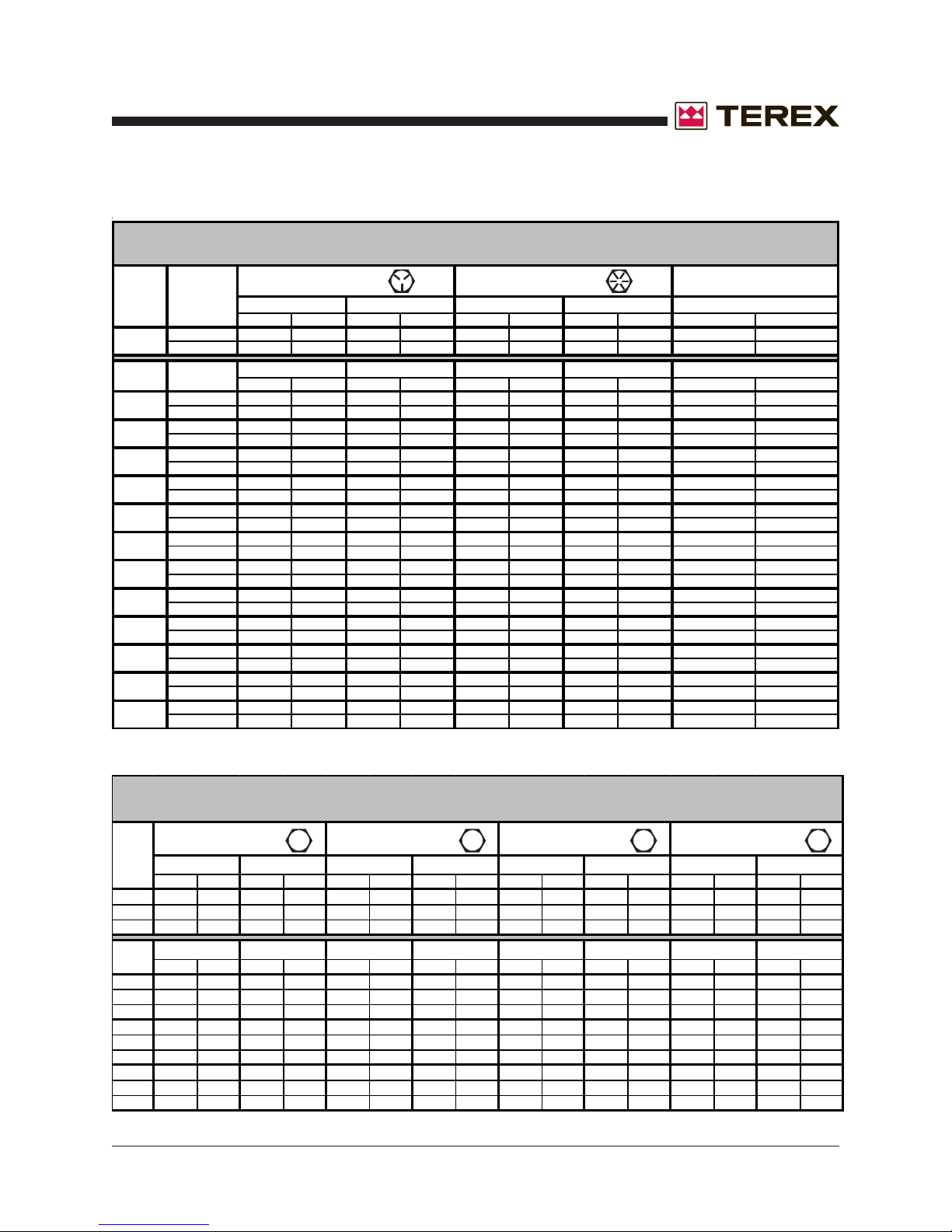
SAE FASTENER TORQUE CHART
• This chart is to be used as a guide only unless noted elsewhere in this manual •
Grade 5
DRYLUBED
in-lbs Nm in-lbs Nm in-lbs Nm in-lbs Nm in-lbs Nm
80 9 100 11.3
LUBED DRY LUBED DRY
ft-lbs Nm ft-lbs Nm ft-lbs Nm ft-lbs Nm ft-lbs Nm
13 17.6 17 23 18 24 25 33.9 21 28.4
23 31.2 31 42
26 35.2 35 47.4
41 55.5 55 74.5
57 77.3 75 101.6
80 108.4 110 149
90 122 120 162
110 149 150 203
130 176 170 230
9
8
7 590 800 790 1071
7
6
220 298 300 406
320 433 430 583
480 650 640 867
530 718 710 962
670 908 890 1206 1080 1464 1440 1952 1220 1654
840 1138 1120 1518 1360 1844 1820 2467 1530 2074
930 1260 1240 1681
1460 1979 1950 2643
1640 2223 2190 2969 2670 3620 3560 4826 3000 4067
110 12.4 140 15.8
120
20 27.1 27 36.6
33 44.7 44 59.6
37 50.1 49 66.4
50 67.8 70 94.7
60 81.3 80 108.4
80 108.4 110 149
90 122 120 162
120 162 150 203
130 176 170 230
160 217 210 284
180 244 240 325
280 379 380 515
310 420 420 569
450 610 610 827
500 678 670 908
680 922 910 1233
750 1016 990 1342
970 1315 1290 1749
1510 2047 2010 2725
2370 3213 3160 4284
Grade 8
13.5
160 18
SPECIFICATIONS
A574 High Strength
Black Oxide Bolts
LUBEDDRYLUBED
130 14.7
140 15.8
LUBED
24 32.5
38 51.5
43 58.3
61 82.7
68 92.1
93 126
105 142
130 176
140 189
180 244
200 271
320 433
350 474
510 691
560 759
770 1044
840 1139
1090 1477
1700 2304
2670 3620
METRIC FASTENER TORQUE CHART
• T his chart i s t o be used as a gu i de onl y unless noted elsewhere in this manual •
Size
(mm)
in-lbs Nm in-lbs N m in-lbs Nm in-lbs N m in-lbs N m in-lbs Nm in-lbs N m in-lbs N m
16 1.8 21 2.4 41 4.63 54 6.18 58 6.63 78 8.84 68 7.75 91 10.3
5
19 3.05 36 4.07 69 7.87 93 10.5 100 11.3 132 15 116 13.2 155 17.6
6
45 5.12 60 6.83 116 13.2 155 17.6 167 18.9 223 25.2 1.95 22.1 260 29.4
7
ft-lbs Nm ft-lbs Nm ft-lbs N m ft-lbs Nm ft-lbs Nm ft-lbs Nm ft-lbs Nm ft-lbs N m
5.4 7.41 7.2 9.88 14 19.1 18.8 25.5 20.1 27.3 26.9 36.5 23.6 32 31.4 42.6
8
10.8 14.7 14.4 19.6 27.9 37.8 37.2 50.5 39.9 54.1 53.2 72.2 46.7 63.3 62.3 84.4
10
18.9 25.6 25.1 34.1 48.6 66 64.9 88 69.7 94.5 92.2 125 81 110 108 147
12
30.1 40.8 40 54.3 77.4 105 103 140 110 150 147 200 129 175 172 234
14
46.9 63.6 62.5 84.8 125 170 166 226 173 235 230 313 202 274 269 365
16
64.5 87.5 86.2 117 171 233 229 311 238 323 317 430 278 377 371 503
18
91 124 121 165 243 330 325 441 337 458 450 610 394 535 525 713
20
124 169 166 225 331 450 442 600 458 622 612 830 536 727 715 970
22
157 214 210 285 420 570 562 762 583 791 778 1055 682 925 909 1233
24
Part No. 116478 AL8000HT Light Tower 2 - 9
DRYLUBED
Class 10.9Class 8.8
LUBEDDRYLUBED
10.9 12.98.84.6
DRY
Class 12.9Class 4.6
LUBED DRY
LUBED DRY LUBED DRYLUBED DRY LUBED DRY
GENSET TORQUE SPECIFICATIONS
Generator FT*LB
Flex Plate to Flywheel 25
Generator Case to Bellhousing 25
Genset Isolators 75
September 2008
2 - 10 AL8000HT Light Tower Part No. 116478

September 2008
Scheduled Maintenance Procedures
Section 3 • Scheduled Maintenance Procedures
About This Section
This section contains detailed procedures for each
scheduled maintenance inspection.
Each procedure includes a description, safety
warnings and step-by-step instructions.
Observe and Obey:
Maintenance inspections shall be completed by
a person trained and qualified on the
maintenance of this machine.
Scheduled maintenance inspections shall be
completed daily, quarterly, semi-annually,
annually and every 2 years as specified on the
Maintenance Inspection Report.
Failure to perform each procedure
as presented and scheduled could
result in death, serious injury or
substantial damage.
Immediately tag and remove from service a
damaged or malfunctioning machine.
Repair any machine damage or malfunction
before operating the machine.
Use only Terex approved replacement parts.
Machines that have been out of service for a
period longer than 3 months must complete the
quarterly inspection.
Unless otherwise specified, perform each
maintenance procedure with the machine in the
following configuration:
· Machine parked on a firm, level surface
· Key switch in the off position
(manual start models)
· Toggle switch in the off position
(automatic start models)
· Mast in the stowed position
· Light switches in the off position
· Wheels chocked
Symbols Legend
Safety alert symbol—used to alert
personnel to potential personal
injury hazards. Obey all safety
messages that follow this symbol
to avoid possible injury or death.
Indicates an imminently hazardous
situation which, if not avoided, will
result in death or serious injury.
Indicates a potentially hazardous
situation which, if not avoided,
could result in death or serious
injury.
Indicates a potentially hazardous
situation which, if not avoided,
may cause minor or moderate
injury.
Indicates a potentially hazardous
situation which, if not avoided,
may result in property damage.
Indicates that a specific result is expected after
performing a series of steps.
Indicates that an incorrect result has occurred
after performing a series of steps.
Part No. 116478 AL8000HT Light Tower 3 - 1
Section 3 • Scheduled Maintenance Procedures
SCHEDULED MAINTENANCE PROCEDURES
September 2008
Maintenance Symbols Legend
The following symbols have been used in this
manual to help communicate the intent of the
instructions. When one or more of the symbols
appear at the beginning of a maintenance
procedure, it conveys the meaning below.
Indicates that tools will be required to
perform this procedure.
Indicates that new parts will be required
to perform this procedure.
Indicates that a cold engine will be
required to perform this procedure.
Indicates that a warm engine will be
required to perform this procedure.
Pre-delivery Preparation Report
The pre-delivery preparation report contains
checklists for each type of scheduled inspection.
Make copies of the Pre-delivery Preparation report
to use for each inspection. Store completed forms
as required.
Maintenance Schedule
There are five types of maintenance inspections
that must be performed according to a schedule—
daily, quarterly, semi-annually, annual and
two year. The
Section
Scheduled Maintenance Procedures
and the
Maintenance Inspection Report
have been divided into five subsections—A, B, C,
D and E. Use the following chart to determine which
group(s) of procedures are required to perform a
scheduled inspection.
Inspection Checklist
Daily or every 8 hours A
Quarterly or every 250 hours A + B
Indicates that dealer service will be
required to perform this procedure.
Semi-annually or every 500 hours A + B + C
Annually or every 1000 hours A + B + C + D
Two years or every 2000 hours A + B + C + D + E
Maintenance Inspection Report
The maintenance inspection report contains
checklists for each type of scheduled inspection.
Make copies of the
Maintenance Inspection Report
to use for each inspection. Maintain completed
forms for a minimum of 4 years or in compliance
with employer, jobsite and governmental
regulations and requirements.
3 - 2 AL8000HT Light Tower Part No. 116478
Pre-DeliverPre-Deliver
Pre-Deliver
Pre-DeliverPre-Deliver
y Preparationy Preparation
y Preparation
y Preparationy Preparation
Fundamentals
It is the responsibility of the dealer to perform the
Pre-delivery Preparation.
The Pre-delivery Preparation is performed prior to each
delivery. The inspection is designed to discover if anything
is apparently wrong with a machine before it is put into
service.
A damaged or modified machine must never be used. If
damage or any variation from factory delivered condition is
discovered, the machine must be tagged and removed from
service.
Repairs to the machine may only be made by a qualified
service technician, according to the manufacturer's
specifications.
Scheduled maintenance inspections shall be performed by
qualified service technicians, according to the
manufacturer's specifications and the requirements listed in
the responsibilities manual.
Instructions
Use the operator’s manual on your machine.
The Pre-delivery Preparation consists of completing the
Pre-operation Inspection, the Maintenance items and the
Function Tests.
Use this form to record the results. Place a check in the
appropriate box after each part is completed. Follow the
instructions in the operator’s manual.
If any inspection receives an N, remove the machine from
service, repair and re-inspect it. After repair, place a check
in the R box.
Legend
Y = yes, completed
N = no, unable to complete
R = repaired
Comments
TEREX Rock Hill
P.O. BOX 3147
Rock Hill, SC 29732 USA
Toll Free (800) 433-3026 in U.S.A. and Canada
Copyright © 2006 by TEREX Corporation. TEREX® is a registered trademark of TEREX
Corporation.
Rev B
Pre-Delivery Preparation Y N R
Pre-operation inspection completed
Maintenance items completed
Function tests completed
Model
Serial number
Date
Machine owner
Inspected by (print)
Inspector signature
Inspector title
Inspector company
Section 3 • Scheduled Maintenance Procedures
September 2008
This page intentionally left blank.
3 - 4 AL8000HT Light Tower Part No. 116478
September 2008
Section 3 • Scheduled Maintenance Procedures
Maintenance Inspection Report
Model
Serial number
Date
Hour meter
Machine owner
Inspected by (print)
Inspector signature
Inspector title
Inspector company
Instructions
· Make copies of this report to use for
each inspection.
· Select the appropriate checklist(s)
for the type of inspection to be
performed.
Daily or 8 hours
Inspection: A
Quarterly or 250 hours
Inspection: A+B
Semi-annually or
500 hours
Inspection: A+B+C
Annually or
1000 hours
Inspection: A+B+C+D
Two year or
2000 hours
Inspection: A+B+C+D+E
· Place a check in the appropriate box
after each inspection procedure is
completed.
· Use the step-by-step procedures in
this section to learn how to perform
these inspections.
· If any inspection receives an “N”, tag
and remove the machine from
service, repair and re-inspect it. After
repair, place a check in the “R” box.
Legend
Y = yes, acceptable
N = no, remove from service
R = repaired
Checklist A - Rev A YNR
A-1 Manuals and decals
A-2 Pre-operation inspect
A-3 Function tests
Perform every 8 hours:
A-4 Engine maintenance -
Isuzu models
A-5 Generator
maintenance
Perform after 10 miles:
A-6 Axle maintenance
Perform after 25 miles:
A-6 Axle maintenance
Perform after 50 miles:
A-6 Axle maintenance
Perform after 40 hours:
A-7 30 day service
Perform every 50 hours:
A-8 Engine maintenance
Perform weekly:
A-9 Hitch maintenance
Perform every 100 hours:
A-10 Grease rotation
bearing
A-11 Engine maintenance -
Kubota models
Perform every 200 hours:
A-12 Engine maintenance -
Kubota models
Checklist B - Rev A YNR
B-1 Battery
B-2 Electrical wiring
B-3 Tires and wheels
B-4 Hydraulic oil analysis
B-5 Engine maintenance -
Isuzu models
B-6 Generator
maintenance
Perform quarterly:
B-7 Hitch coupler
maintenance
Perform every 400 hours:
B-8 Engine maintenance -
Kubota models
Perform every 3000 miles:
B-9 Axle maintenance
Checklist C - Rev A YNR
C-1 Extend/retract cables
and pulleys
C-2 Engine maintenance
Perform every 6000 miles:
C-3 Axle maintenance
Perform every 750 hours:
C-5 Engine maintenance -
Isuzu models
Perform every 800 hours:
C-6 Engine maintenance -
Kubota models
Part No. 116478 AL8000HT Light Tower 3 - 5
Section 3 • Scheduled Maintenance Procedures
MAINTENANCE INSPECTION REPORT
September 2008
Model
Serial number
Date
Hour meter
Machine owner
Inspected by (print)
Inspector signature
Inspector title
Inspector company
Instructions
· Make copies of this report to use for
each inspection.
· Select the appropriate checklist(s)
for the type of inspection to be
performed.
Daily or 8 hours
Inspection: A
Quarterly or 250 hours
Inspection: A+B
Semi-annually or
500 hours
Inspection: A+B+C
Annually or
1000 hours
Inspection: A+B+C+D
Two year or
2000 hours
Inspection: A+B+C+D+E
· Place a check in the appropriate box
after each inspection procedure is
completed.
· Use the step-by-step procedures in
this section to learn how to perform
these inspections.
· If any inspection receives an “N”, tag
and remove the machine from
service, repair and re-inspect it. After
repair, place a check in the “R” box.
Legend
Y = yes, acceptable
N = no, remove from service
R = repaired
Checklist D - Rev A YNR
D-1 Engine maintenance -
Kubota models
D-2 Tower rotation bearing
bolts
D-3 Hydraulic filter
D-4 Engine maintenance -
Isuzu models
Perform every 1250 hours:
D-5 Engine maintenance -
Isuzu models
Perform every 1500 hours:
D-6 Engine maintenance
D-7 Generator
maintenance
Perform annually:
D-8 Tongue and outrigger
jack maintenance
Perform every 12,000 miles:
D-9 Axle maintenance
Checklist E - Rev A YNR
E-1 Test or replace
hydraulic oil
Perform every 3000 hours:
E-2 Engine maintenance -
Kubota models
Perform every 2 years:
E-3 Engine maintenance -
Kubota models
Perform every 4500 hours:
E-4 Generator
maintenance
Perform every 15,000 hours:
E-5 Generator
maintenance
Comments
3 - 6 AL8000HT Light Tower Part No. 116478

September 2008
Section 3 • Scheduled Maintenance Procedures
REV A
Checklist A Procedures
A-1
Inspect the Manuals and Decals
Note: Terex specifications require that this
procedure be performed daily or every 8 hours,
whichever comes first.
Maintaining the operator’s and safety manuals in
good condition is essential to safe machine
operation. Manuals are included with each machine
and should be stored in the container provided in
the cabinet. An illegible or missing manual will not
provide safety and operational information
necessary for a safe operating condition.
In addition, maintaining all of the safety and
instructional decals in good condition is mandatory
for safe machine operation. Decals alert operators
and personnel to the many possible hazards
associated with using this machine. They also
provide users with operation and maintenance
information. An illegible decal will fail to alert
personnel of a procedure or hazard and could result
in unsafe operating conditions.
3 Open the operator's manual to the decals
inspection section. Carefully and thoroughly
inspect all decals on the machine for legibility
and damage.
Result: The machine is equipped with all
required decals, and all decals are legible and in
good condition.
Result: The machine is not equipped with all
required decals, or one or more decals are
illegible or in poor condition. Remove the
machine from service until the decals are
replaced.
4 Always return the manuals to the storage
container after use.
Note: Contact your authorized Terex distributor if
replacement manuals or decals are needed.
1 Check to make sure that the operator's and
safety manuals are present and complete in the
storage container inside the cabinet.
2 Examine the pages of each manual to be sure
that they are legible and in good condition.
Result: The operator's manual is appropriate for
the machine and all manuals are legible and in
good condition.
Result: The operator's manual is not appropriate
for the machine or all manuals are not in good
condition or are illegible. Remove the machine
from service until the manual is replaced.
Part No. 116478 AL8000HT Light Tower 3 - 7

Section 3 • Scheduled Maintenance Procedures
September 2008
CHECKLIST A PROCEDURES
A-2
Perform Pre-operation
Inspection
Note: Terex specifications require that this
procedure be performed every 8 hours or daily,
whichever comes first.
Completing a pre-operation inspection is essential
to safe machine operation. The pre-operation
inspection is a visual inspection performed by the
operator prior to each work shift. The inspection is
designed to discover if anything is apparently wrong
with a machine before the operator performs the
function tests. The pre-operation inspection also
serves to determine if routine maintenance
procedures are required.
Complete information on how to perform this
procedure is available in the appropriate Operator's
Manual. Refer to the Operator's Manual on your
machine.
REV A
A-3
Perform Function Tests
Note: Terex specifications require that this
procedure be performed every 8 hours or daily,
whichever comes first.
Completing the function tests is essential to safe
machine operation. Function tests are designed to
discover any malfunctions before the machine is
put into service. A malfunctioning machine must
never be used. If malfunctions are discovered, the
machine must be tagged and removed from
service.
Complete information on how to perform this
procedure is available in the appropriate Operator's
Manual. Refer to the Operator's Manual on your
machine.
3 - 8 AL8000HT Light Tower Part No. 116478
 Loading...