

Terex AL4000D2 Series, 833002 Operator, Service & Parts Manual
November 2006
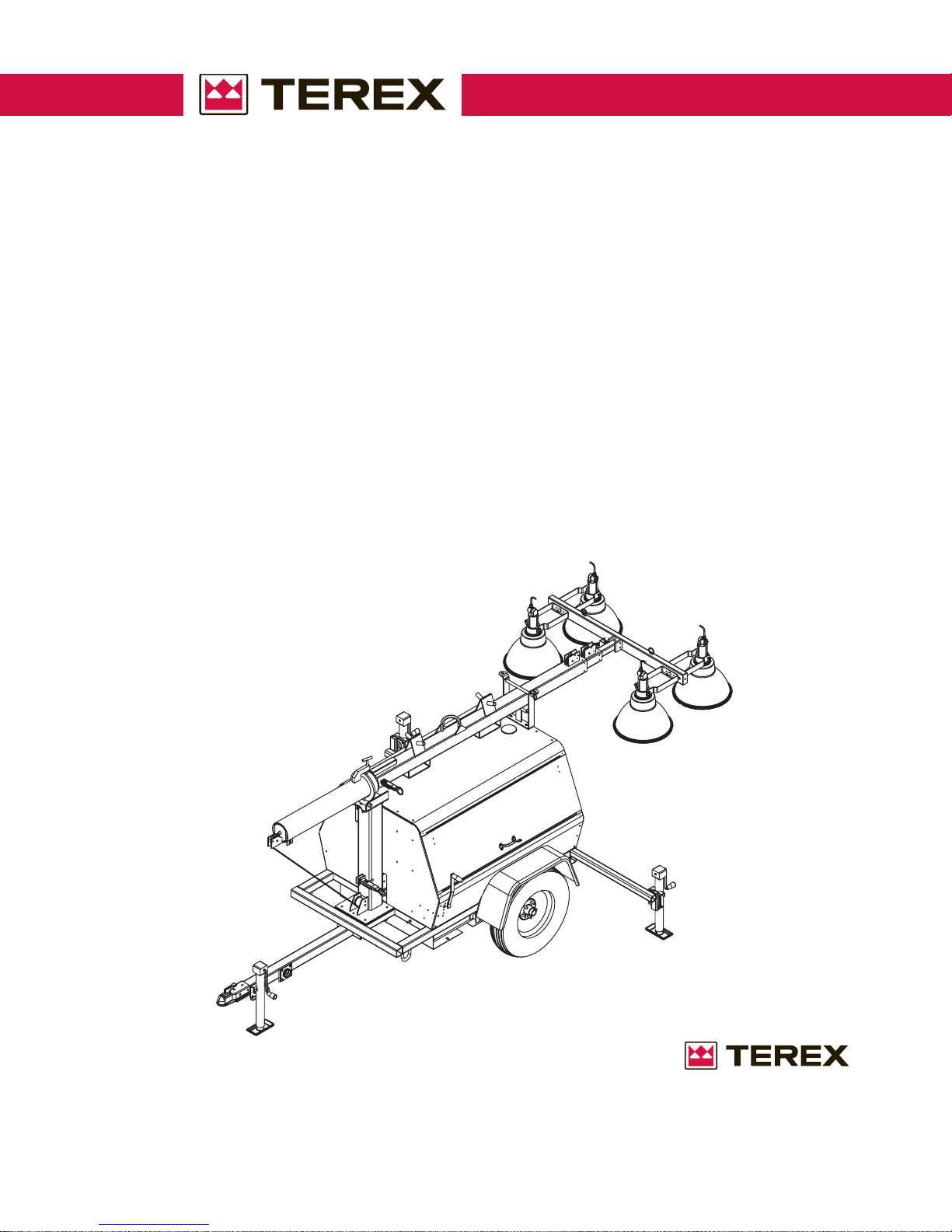
OPERATOR/SER VICE
& PARTS MANUAL
Series AL4000D2
Light Tower
PART NUMBER 833002
REVISION A
November 2006
TOLL FREE 800-433-3026
FAX (Part s Dept) 800-633-5534
Part No. 833002 Rev A AL4000 Light Tower 1
P .O. BOX 3147
ROCK HILL, S.C. 29732 USA

November 2006
TABLE OF CONTENTS
OPERATOR’S MANUAL
T o the Operator ................................................................................................................4
Safety Alert Symbols ........................................................................................................5
General Safety ............................................................................................................6-10
Receipt of Delivery Checklist.......................................................................................... 11
Transport & Towing.........................................................................................................12
Setup ........................................................................................................................13-16
Operating Instructions................................................................................................17-21
Maintenance .............................................................................................................22-24
Specifications and Dimensions.................................................................................25-26
T orque S pecifications..................................................................................................... 27
Troubleshooting.........................................................................................................28-32
Warrranty ..................................................................................................................33-34
Serial Number Record ................................................................................................... 35
Model Number Identification ........................................................................................... 36
Recomended Oil ............................................................................................................ 37
Wire Rope Replacement...........................................................................................38-42
PARTS MANUAL
Wiring Diagrams.......................................................................................................44-50
General Information Parts Manual................................................................................... 52
Parts Ordering Information ............................................................................................. 53
Trailer Frame/Tongue/Outriggers ....................................................................................54
Fuel T ank .......................................................................................................................55
Axle Assembly................................................................................................................ 56
Cabinet Assembly .......................................................................................................... 58
Cabinet Assembly (Top & Doors) ................................................................................... 60
Cabinet Decals .............................................................................................................. 62
T ower Assembly ............................................................................................................. 63
4” T ower Section ............................................................................................................64
4” T ower Section (Sheave & Shim).................................................................................65
3” T ower Section ............................................................................................................66
2” T ower Section ............................................................................................................67
T ower Crossarm Fixture .................................................................................................68
6” Round Tube................................................................................................................69
2 AL4000 Light Tower Part No. 833002 Rev A

November 2006
TABLE OF CONTENTS
PARTS MANUAL (Continued)
T ower Base Assembly....................................................................................................70
Winch Assembly.............................................................................................................72
Engine/Genset Assembly ............................................................................................... 74
Radiator Assembly.........................................................................................................75
Radiator Mounting Bracket............................................................................................. 76
Generator Mounting Bar ................................................................................................. 77
Electrical Control Box Assembly..................................................................................... 78
MH/HPS Light Fixture Assembly..................................................................................... 80
Ballast Assembly............................................................................................................ 82
Coil Cord & Junction Box ...............................................................................................83
Trailer Hitches ................................................................................................................84
AL4000 Options........................................................................................................85-86
Part No. 833002 Rev A AL4000 Light Tower 3
November 2006
TO THE OPERATOR
DO NOT ATTEMPT TO SETUP, OPERATE, OR WORK ON THE LIGHT T OWER
UNLESS YOU HAVE READ AND STUDIED THIS MANUAL AND THE ENGINE AND
GENERATOR MANUALS CAREFULLY. READING THESE MANUALS WILL TEACH
YOU HOW TO SAFELY SETUP, OPERATE, AND PROPERLY MAINTAIN THE
TOWER AND ITS COMPONENTS.
REMEMBER THAT YOU ARE THE KEY TO SAFETY. GOOD SAFETY PRACTICES
NOT ONLY PROTECT YOU, BUT ALSO THOSE WORKING AROUND YOU. MAKE
THIS MANUAL A WORKING PART OF YOUR SAFETY PROGRAM.
An operator should never use drugs, alcohol or any other substance which can change his
alertness or coordination.
Do not work on this equipment when mentally or physically fatigued.
This manual is compiled from information available and current at time of approval for printing.
Terex reserves the right to improve its products without giving prior notice or incurring any obligation.
If this manual becomes lost, order a new one from Terex so future operation and maintenance
personnel may read these instructions.
4 AL4000 Light Tower Part No. 833002 Rev A
November 2006
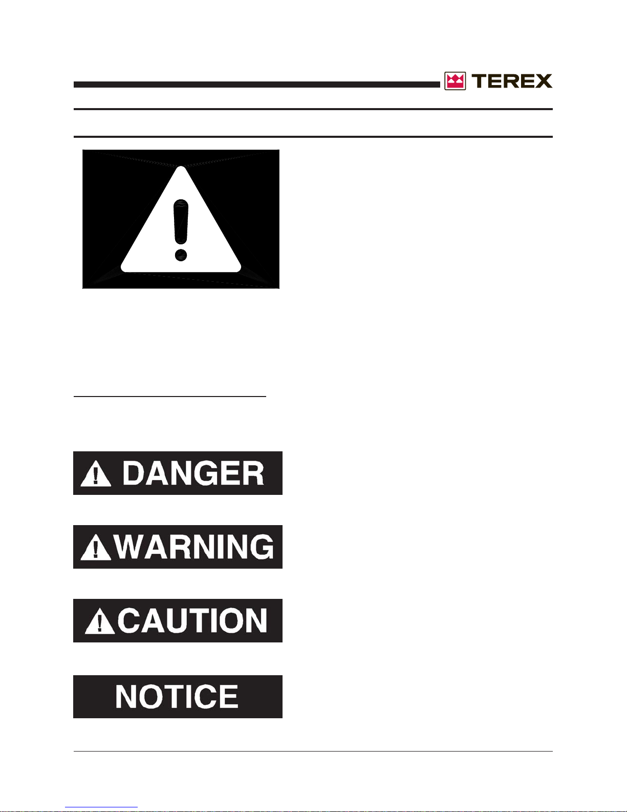
SAFETY ALERT SYMBOLS
MEANS:
ATTENTION! BE ALERT!
YOUR SAFETY IS INVOLVED
THIS SAFETY SYMBOL IS USED FOR IMPORTANT SAFETY MESSAGES. WHEN YOU SEE THIS SYMBOL, FOLLOW THE SAFETY
MESSAGE TO AVOID PERSONAL INJURY OR PROPERTY DAMAGE.
UNDERSTANDING SIGNAL WORDS
A signal word - DANGER, WARNING or CAUTION is used with the safety alert symbol.
DANGER Identifies the hazard or unsafe practice
that will result in severe injury or death.
WARNING Identifies the hazard or unsafe practice
that could result in severe injury or death.
CAUTION Identifies the hazard or unsafe practice
that could result in minor injury or property damage.
NOTICE Identifies important installation, operation
or maintenance information.
Part No. 833002 Rev A AL4000 Light Tower 5
November 2006
GENERAL SAFETY
DO NOT OPERATE THE AL4000 LIGHT T OWER WITHOUT
READING THIS OPERATOR’S MANUAL.
DO NOT WORK ON OR OPERATE THE LIGHT TOWER WHILE UNDER THE INFLUENCE OF PERFORMANCE IMPAIRING DRUGS OR ALCOHOL.
SAFETY ALERT SYMBOL
Stop and take time to read ALL Safety alert messages. Follow the safety messages to avoid
personal injury or property damage.
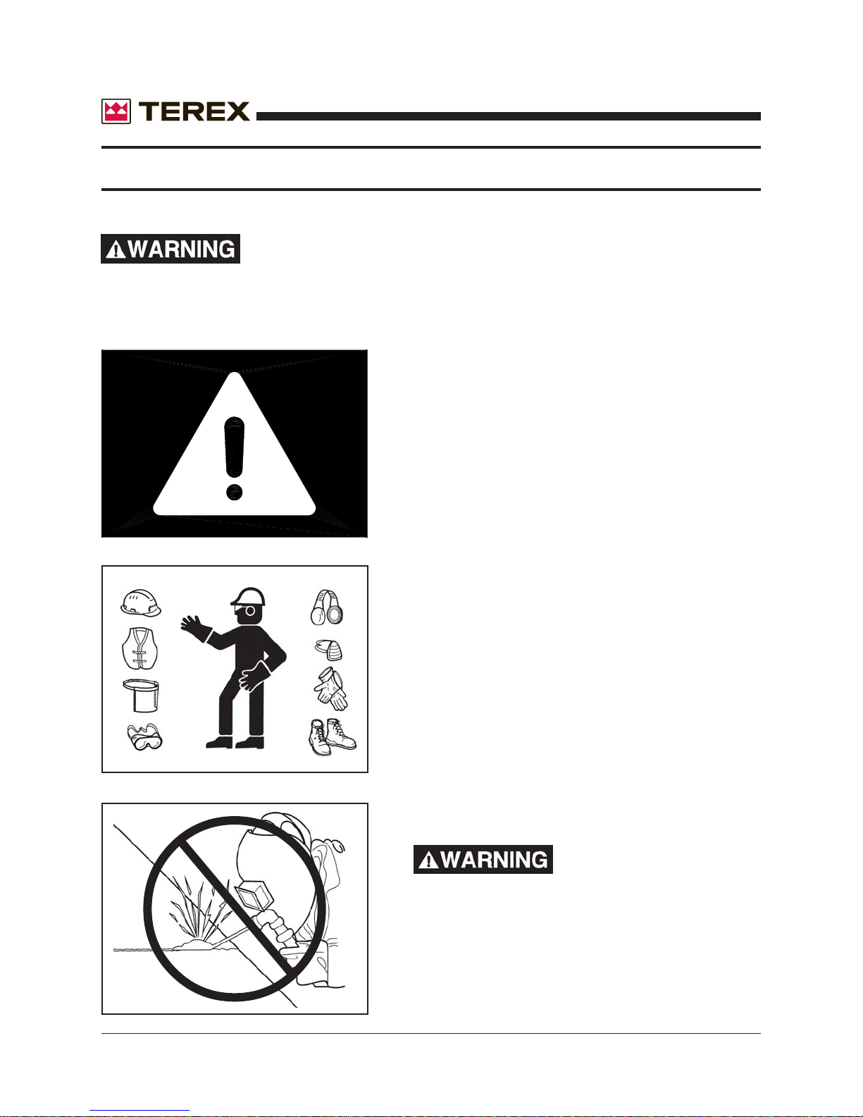
ACCIDENT PREVENTION
Use protective clothing and safety equipment.
Always wear approved safety equipment such as
gloves, safety boots, safety hard hat, goggles, ear
protection, and dust masks when necessary.
Wear protective clothing that is snug and belted
where required.
UNAUTHORIZED WELDING
UNAUTHORIZED
WELDING CAN CAUSE
STRUCTURAL FAILURE OR PERSONAL
INJURY.
DO NOT weld on any structural member.
6 AL4000 Light Tower Part No. 833002 Rev A
Any unauthorized welding or repair procedure will
void the warranty .
November 2006
GENERAL SAFETY
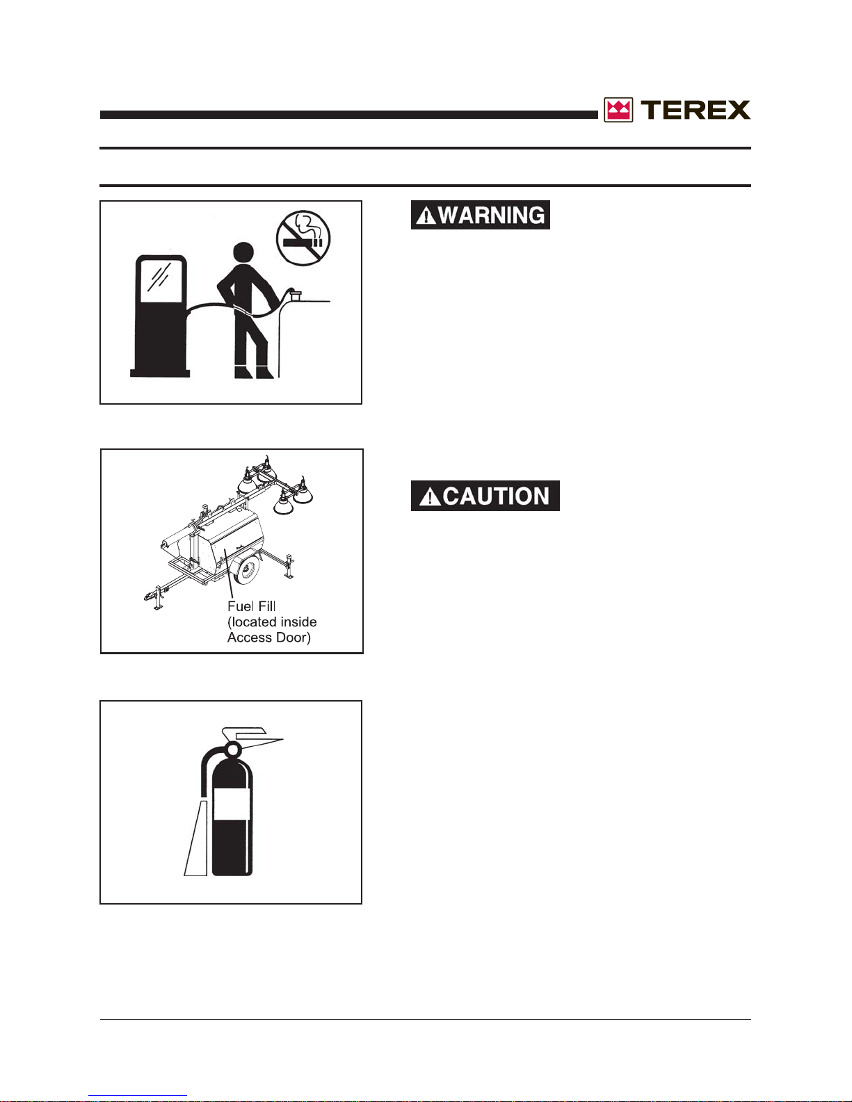
FUELING
ALWAYS handle fuel with care. It is highly flam-
mable.
ALWAYS stop engine before refueling. Fill fuel
tank outdoors.
Be sure the fuel supply has a positive shut-off
valve.
DO NOT replace fuel lines with materials different
from those supplied as original equipment.
FIRES CAN CAUSE
SEVERE PERSONAL
INJURY OR MACHINE
DAMAGE.
Prevent fires by keeping the light tower and its
surrounding area clean.
DO NOT refuel while smoking or when near open
flame or sparks.
DO NOT refuel the engine when it is hot. Allow to
cool for several minutes before refueling.
DO NOT spill fuel inside the engine compartment.
If fuel has leaked, wipe it up and have leak re-
paired before next use.
Have a fire extinguisher nearby . Be sure the
extinguisher is properly maintained and be familiar
with its use. Extinguishers rated ABC by the NFPA
are appropriate for all applications.
Part No. 833002 Rev A AL4000 Light Tower 7

November 2006
GENERAL SAFETY
EXHAUST GASES ARE TOXIC. DO NOT USE INDOORS
UNLESS PROPERLY VENTILATED OR AN EXHAUST
SCRUBBER IS USED.
Check exhaust system regularly for leaks and ensure that the exhaust manifolds are secure and
not warped.
Make sure the unit is well ventilated.
ELECTRICAL SAFETY
This equipment utilizes high voltage circuits. Always exercise extreme caution when trouble
shooting or repairing any electrical circuit.
The electrical circuits in this light tower complete their paths back to the generator within the
equipment. The neutral conductor at the generator is bonded to the equipment frame. Ground
wires within the system are also bonded to the equipment frame.
Always ground the unit when possible. Consult local electrical codes for grounding
instructions.
A grounding lug has been added to the trailer frame for your convenience.
Disconnect electrical power and turn off engine before removing protective covers on high
voltage electrical enclosures.
Beware of a cut or damaged power cord. Have a qualified electrician replace immediately .
When troubleshooting indicates a malfunction in the high voltage AC system, pass the task to a
qualified and trained electrician.
DO NOT TOUCH HOT PARTS
The exhaust manifold and tail pipe are very hot. Parts of the engine are also hot. Use protective
gloves when handling hot parts.
The light fixtures become very hot during operations. To avoid burns, always allow any fixture to
cool before handling.
8 AL4000 Light Tower Part No. 833002 Rev A
November 2006
GENERAL SAFETY
BATTERY HAZARDS
Lead acid batteries can be dangerous. The sulfuric acid in the battery can cause severe skin and
eye burns. The hydrogen gas emitted during charging can explode if an arc or flame is present.
DO NOT smoke while servicing the battery.
DO NOT allow tools to touch battery terminals and create an arc.
Disconnect the negative terminal of the battery when working on the engine or other parts to
prevent accidental arcing. Disconnect the negative cable at the end away from the battery.
DO NOT remove the vent caps when charging the battery.
Always wear eye protection when servicing the battery .
If acid gets on skin or eyes, immediately flush under running water and obtain medical attention.
METAL HALIDE LAMPS PRODUCE SHORTWAVE ULTRAVIOLET RADIATION AND CAN CAUSE SERIOUS SKIN AND EYE
BURNS OR INFLAMMATION IF THE OUTER ENVELOPE OF
THE LAMP IS BROKEN OR PUNCTURED.
DO NOT use where people will remain close to the lamps for more than a few minutes unless
adequate shielding or other safety precautions are used.
KEEP ALL BODY P ARTS AND CLOTHING AW AY FROM
MOVING PARTS
Loose jackets, shirts, sleeves, and especially neckties should not be worn while working on or
running the unit.
Only remove guards or protective devices from unit temporarily to gain access for maintenance.
Always replace guards immediately after servicing. Never remove guards while unit is operating.
Keep your hands away from moving parts, particularly clear of the radiator fan and alternator
belts when the engine is running.
Part No. 833002 Rev A AL4000 Light Tower 9
November 2006
GENERAL SAFETY
BEWARE OF TRAFFIC HAZARDS
Stand clear of traf fic when st arting or checking the unit along the road.
Check the fuel tank, oil pan, and fuel and oil lines for leaks that would spill fuel or oil on the road.
Check fasteners and mounting brackets periodically to insure all are tight and nothing is in
danger of falling off during transit.
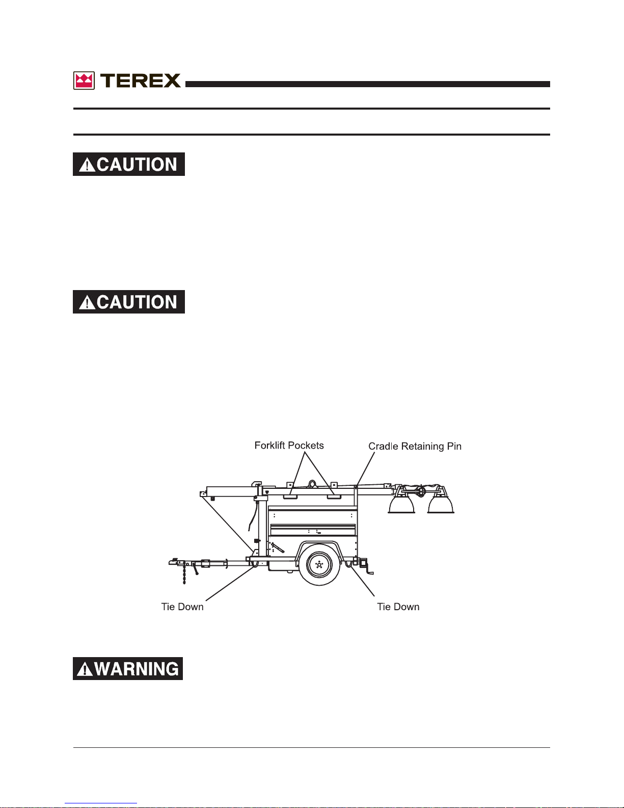
Be careful when lifting. Never suspend any other equipment
from the shipping tie downs.
Use the lifting eye or forklift pockets on the tower for lifting the trailer and tower assembly only
(with tower and cabinet).
Make sure any tie-downs at the bottom of the trailer are released, and the cradle retaining pin is
inserted and secured, prior to lifting.
NEVER CLIMB ON TOP OF THE CABINET AND/OR TOWER
WHEN ERECTED OR RETRACTED.
10 AL4000 Light Tower Part No. 833002 Rev A

November 2006
RECEIPT OF DELIVERY CHECKLIST
The tower will be serviced, tested and ready for operation upon delivery . Terex recommends the
following checks:
Insure there is no freight handling damage which should be charged against the carrier.
Make sure the telescoping boom is secure.
Make sure the crosshead assembly is secure.
Check the front and rear jacks for security and proper operation.
Check the outriggers for security and proper operation.
Check that the tires are not damaged, under inflated or that any lugs are loose.
Check the engine/generator for obvious damage, loose connections, or leaks.
Check the control panel for damage or loose connections.
Check the boom wires for obvious damage or loose connections.
Check the light fixtures for damage to the lamps, lenses, reflector or etc.
Check the winches, cables and pulleys for damage and proper operation.
Check the exhaust system for damage.
Check all fluid levels; battery , radiator , and engine oils.
Insure manuals are in the pocket provided inside the unit.
Part No. 833002 Rev A AL4000 Light Tower 11
November 2006
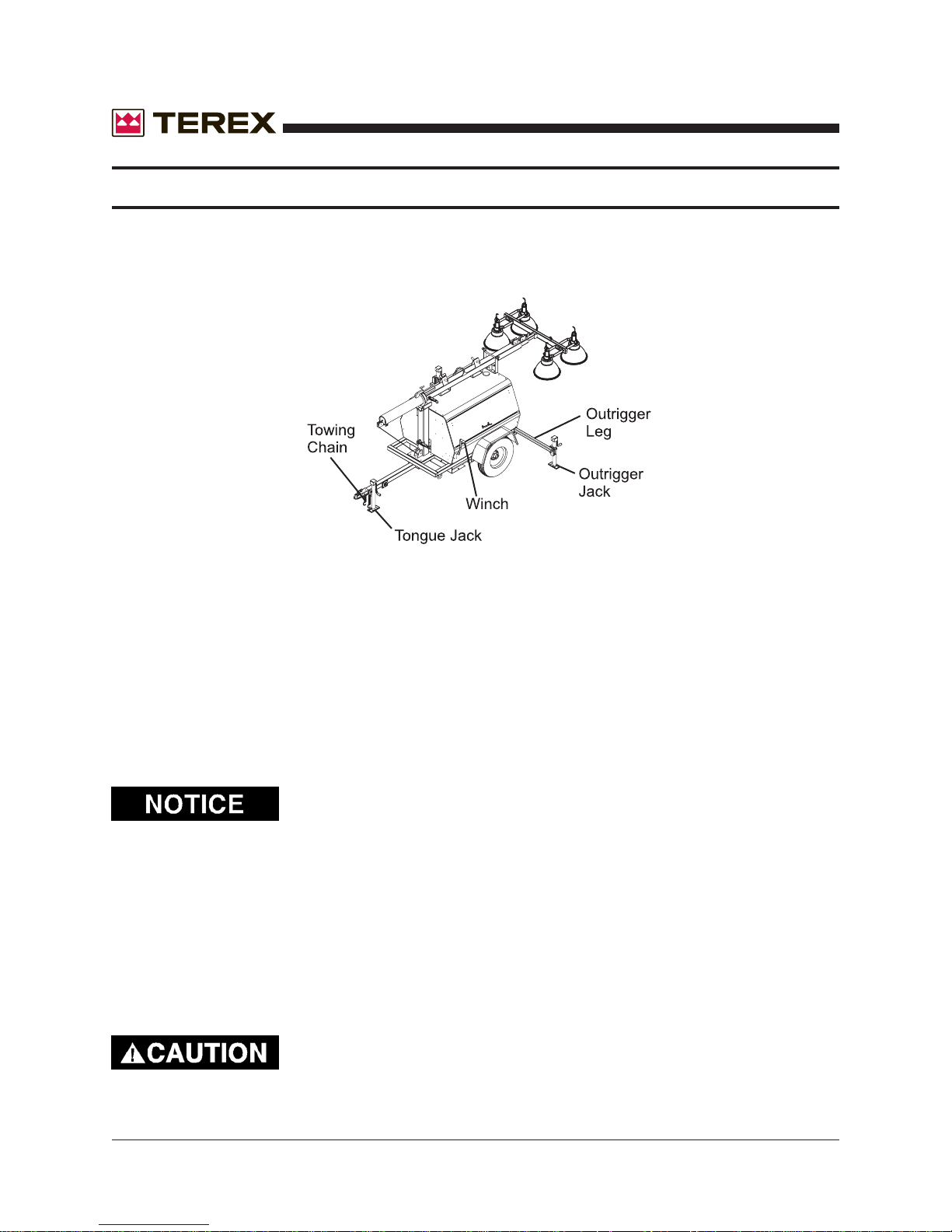
TRANSPORT & TOWING
1. Using the front leveling jack, securely attach the light tower to the transporting vehicle.
2. Insure that the coupler is properly secured to the towing vehicle and attach the safety
chains.
ALWAYS USE THE PROPER TRAILER HITCH AND SAFETY
CHAINS. OBEY ALL LOCAL OR STATE D.O.T. LA WS WHEN
TOWING A LIGHT TOWER.
FAILURE TO PROPERLY SECURE THE TRAILER TO THE
TOWING VEHICLE MAY RESULT IN SERIOUS INJURY OR
DEATH.
3. Retract and rotate the front leveling jack into its stowed position.
4. Check the tires for proper inflation (32psi) and verify the lug nuts are tight.
5. Position all outriggers and jacks into the stowed or travel position.
6. Verify that the fixtures are secure and ready for transport.
7. Secure all loose locking pins and retainers.
8. Make sure all doors are closed and tightly locked.
9. Remove tire chocks.
T owing of a Terex light tower is approved with the light fixtures in place on the crosshead assembly for all off road
terrain and highway towing as long as the following speed
limits are followed:
Highway towing - 60 MPH max
Off road towing - 10 MPH max
Severe damage may occur from excessive speeds. Damage
created by abuse will void the manufacturer’s warranty .
12 AL4000 Light Tower Part No. 833002 Rev A
November 2006
SETUP
A. Move the light tower to desired location keeping the following in mind:
1. The light tower should not be placed where those working under the light are either:
a. Forced to look into the light regularly.
b. Forced to work with their backs to the light (shadows will block the light from the
work area).
2. The area where the tower is positioned should be relatively level for safe and proper
operation of the unit.
3. The light tower should be located on the same level or on ground higher than the work
area.
B. Use tire chocks in front of and behind each tire whenever possible. Always use tire
chocks on an incline.
C. Disconnect the towing chain.
D. Unhitch from the towing vehicle as follows:
1. Rotate the tongue jack into position (90 degrees), release the hitch pin and raise the
tongue off the towing vehicle.
E. Level the trailer , using the jacks as follows:
1. Extend the front outriggers until the outrigger pins lock into place. Rotate
the jack on each outrigger into vertical position and lock into place.
2. Rotate the rear jack and lock into the vertical position.
3. Start at the highest jack position. Rotate the jack handle until the jack foot touches the
ground.
4. Raise the other jacks to level trailer.
OUTRIGGERS ARE NOT DESIGNED TO LIFT THE TIRES OFF
THE GROUND.
Insure that all jacks are down to prevent the tower from
tipping over backwards when raised.
NEVER ATTEMPT TO MOVE THE TOWER WHILE THE LEVELLING JACK ARE DOWN. SERIOUS MACHINE DAMAGE
WILL RESULT.
Part No. 833002 Rev A AL4000 Light Tower 13
SETUP
F. When applicable, drive grounding rod into earth. (Grounding rod not included)
1. Drive the rod into the ground and secure the grounding wire to the lug located on the
trailer frame.
November 2006
G. When applicable, install the floodlights on the crossarm.
1. Remove the light fixtures from their packing boxes and install them on the crossarm
with the lens facing the ground.
2. The cord on the fixture should be on the side closest to the trailer so the cord entry is
beneath the fixture when the tower is raised (this reduces moisture problems and
insures the water weep hole in the fixture is down).
3. Set the vertical aim for each light fixture by adjusting the light fixtures and tightening
the lower bolt.
Never adjust fixtures with power on.
4. Set the spread between the fixtures horizontally by adjusting the fixtures and tightening
the mounting nut.
5. The light fixtures may be left on the unit when towed around the job site.
6. Plug each fixture into the receptacles provided. Plug into the numbered receptacles in
a clockwise rotation starting at the upper or 1:00 o’clock position. This makes trouble
shooting easy without lowering the tower.
If Tungsten Halogen lamps are used, the cord must be routed
and secured away from the fixture. Failure to do so may
result in cord burn-through and short circuit due to the high
fixture temperature.
14 AL4000 Light Tower Part No. 833002 Rev A
November 2006
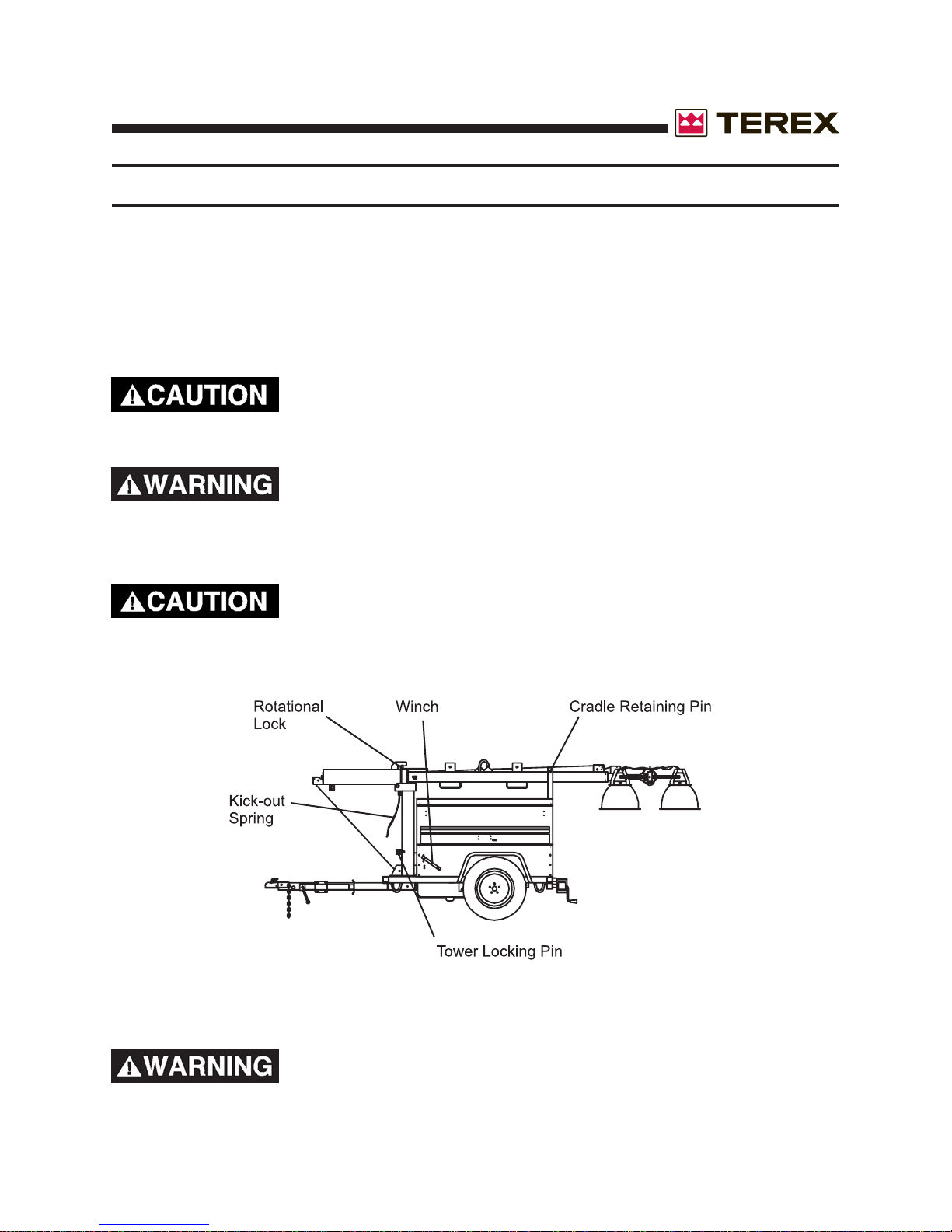
SETUP
H. Raising the tower as follows:
1. Remove the tower travel locking pin from the cradle at the rear of the cabinet.
2. Remove the tower locking pin from the tower base. Using the lower pivot winch, raise
the tower to the vertical position. Reinsert the tower locking pin into the tower base.
If there is any difficulty in tilting the boom vertically , check the
tailhook and hook. The tailhook may need to be released.
BEWARE OF PINCH POINTS WHEN ERECTING OR STOWING THE TELESCOPING TOWER. A LOSS OF DIGITS OR
LIMBS MAY RESULT FROM UNSAFE PRACTICES.
Do not attempt to lean the tower down when it is extended.
Serious damage may occur.
WHEN RAISING THE BOOM, MAKE SURE THE BOOM
WIRING DOES NOT BECOME ENTANGLED.
Part No. 833002 Rev A AL4000 Light Tower 15

November 2006
SETUP
THE AUTOMATIC BRAKE MUST BE WORKING ON THE
TELESCOPING WINCH. THE WINCH SHOULD NOT ALLOW
THE TOWER TO DROP DOWN WHEN THE HANDLE IS
RELEASED.
UNDER NO CIRCUMSTANCES SHOULD THE LIGHT
TOWER BE MOVED WHEN THE BOOM IS IN A VERTICAL
POSITION.
3. Release the tower rotational lock and adjust the lights to the desired area. Once
positioned correctly , retighten the rotational lock.
16 AL4000 Light Tower Part No. 833002 Rev A
November 2006
OPERATING INSTRUCTIONS
READ ALL DIRECTIONS IN MANUAL CAREFULLY
BEFORE OPERATING EQUIPMENT
DO NOT RAISE TOWER IN THE VICINITY OF
OVERHEAD POWER LINES!
1. Move Light Tower to desired location keeping the following in mind:
A. The light tower should not be placed where those working under the light are either:
1. Forced to look into the light regularly .
2. Forced to work with their backs to the light (shadows will block the light from the
work area).
B. The area where the tower is positioned should be relatively level.
C. The light tower should be located on the same level or on ground higher than the area
being lighted (higher light mounting heights reduce the shadow length).
D. Unit should be level to insure smooth trouble-free tower telescoping. Tower may not
telescope down properly when unit is not level.
2. Unhitch from the towing vehicle as follows:
A. Engage the trailer braking system, especially if trailer is not on level ground.
CAUTION: If electrical or manual braking system is not supplied, chock the wheels
instead.
B. Swing the tongue jack into position and raise the tongue off the towing vehicle.
3. Level the trailer, using the jacks as follows:
A. Extend the rear outriggers until the springs lock into place. Swing the jack on each
outrigger into vertical position.
B. St art at the highest jack position. Rot ate the jack handle until the jack foot touches the
ground.
C. Raise the other jacks to level trailer
down to prevent the tower from tipping over backwards when raised.
ensure that the rear jacks are
4. Drive grounding rod into earth.
Part No. 833002 Rev A AL4000 Light Tower 17
OPERATING INSTRUCTIONS
5. Install the floodlights on the crossarm:
A. Remove the light fixtures from the tower by rotating the wingnuts to free the lights.
Install them on the cross arm studs with the lens facing the ground.
B. The cord on the fixture should be on the side closest to the trailer so the cord entry is
beneath the fixture when the tower is raised ( this reduces moisture problems and
insures the water weep hole in the fixture is down).
C. Set the vertical aim for each light fixture by adjusting the light fixtures and tightening the
T-handle located on the fixture.
D. Set the spread between the light fixtures horizontal aiming by adjusting the fixtures and
tightening the wing nut.
E. The unit may be transported with the light fixtures mounted on the crossarm if they
are pointed toward the ground.
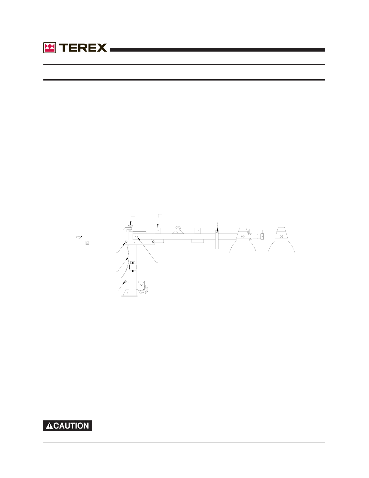
"T" BOLT
FIXTURE TRAVEL STORAGE BRACKETS
November 2006
TRAVEL LOCKING PIN
PIVOT PIN
TELESCOPING LOCKING PIN
KICK-OUT SPRING
VERTICAL LOCKING PIN
6. Raising the tower (refer to drawing above):
A. Remove the tower travel-locking pin from the cradle at the rear of the cabinet.
B. Aim the fixtures, both horizontally and vertically, to the estimated angles that will light
the work area.
C. Using the winch, raise the tower to the vertical position. The tower-locking pin at the
base of the pivot post will lock automatically and you will hear it “snap” into place.
Insert manual pin into locking device.
D. Release the tension on the cable by backing the winch off slightly and pull the tele-
scoping locking pin on the galvanized tower section. Hold this out while turning the
winch to raise the tower. After the tower has telescoped slightly, the locking pin can be
released. Raise the tower to the desired height.
DO NOT ATTEMPT TO LEAN THE TOWER DOWN BELOW 45°
WHEN IT IS EXTENDED-SERIOUS DAMAGE MAY OCCUR!
18 AL4000 Light Tower Part No. 833002 Rev A
November 2006
OPERATING INSTRUCTIONS
7. Start the Engine/Generator Set
A. Ensure the circuit breakers are turned “OFF”. This prevents the engine from
starting under load and prevents electrical equipment from being subjected to
improper voltage and frequency .
B. Check the oil, fuel, and coolant levels. If the fuel tank is empty, it may be necessary to
bleed the fuel line after filling the tank (see engine instruction book for procedure).
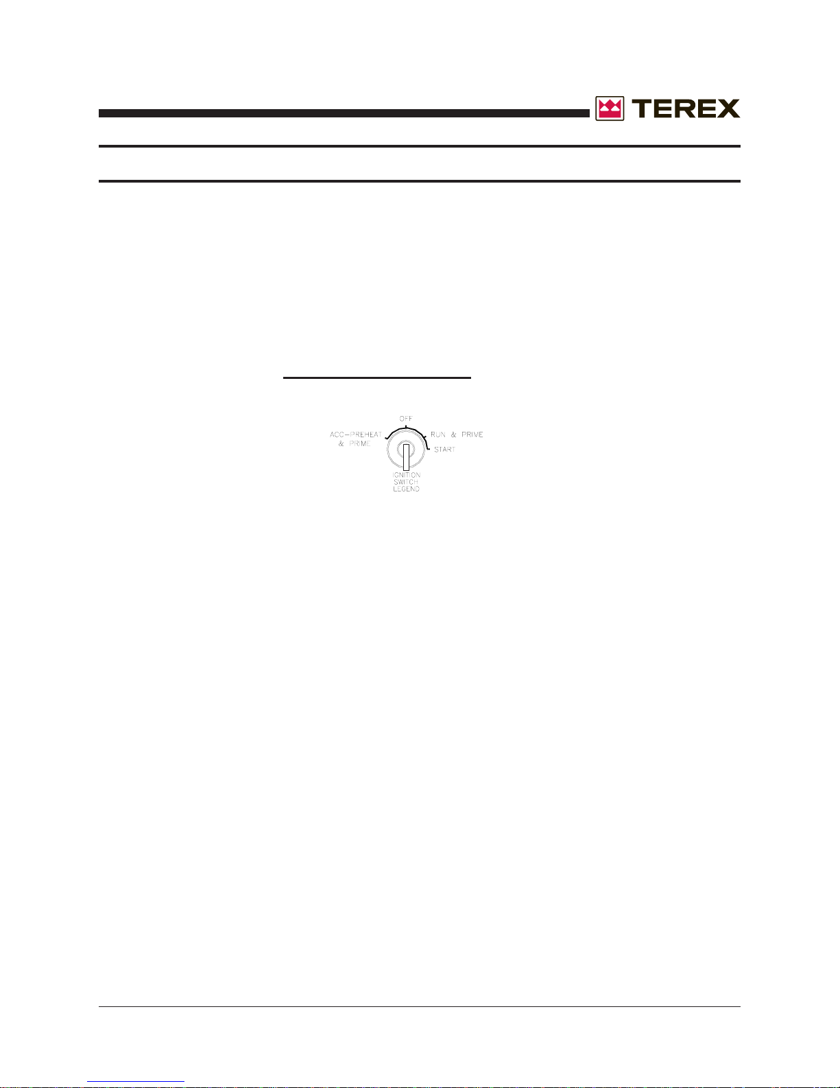
C. Turn the ignition switch to the “ACC” position (see diagram below). Press the preheat
push-button for a
button longer than the time specified or damage may occur.
maximum of 20 SECONDS. Do not engage the preheat
D. Turn the ignition switch to the “ST AR T” position to engage the engine. After the engine
starts, release the switch so that it returns to the “RUN” position. Let the engine come
up to speed and stabilize (review the engine operating procedures in the manufacturers handbook). Note: If engine will not start, leave switch in run position for additional
10-20 seconds to completely prime the fuel system. Then repeat step “C” and start
engine.
E. Turn on the main circuit breaker.
8. Turn on the floodlights:
A. Turn the circuit breakers “ON” and ensure all lamps come on. Allow a minimum of
two (2) minutes for lamps to reach full luminance.
B. If required, rotate the tower to aim the lights as desired. Tighten the tower rotating
locking bolt.
C. Adjust the tower vertically and adjust lighting direction of individual fixtures if required.
9. Turn off the floodlights:
Part No. 833002 Rev A AL4000 Light Tower 19
OPERATING INSTRUCTIONS
A. Turn light circuit breakers of f.
B. Turn engine switch to “OFF” to shut down the engine.
DO NOT SHUT DOWN ENGINE PRIOR TO TURNING LIGHTS OFF.
ALLOW LAMPS TO COOL AT LEAST TEN (10) MINUTES BEFORE
MOVING THE TOWER TO AVOID BREAKING LAMPS.
10. Lowering the tower to traveling position:
A. Using the winch, telescope the tower down to its fully retracted position until the
telescoping locking pin snaps into place.
November 2006
B.
vertical lock pin at the bottom of the pivot post. This insures the tower is completely
lowered and cannot be damaged by telescoping out while in the travel position.
C. Loosen rotating lock.
D. Rotate the tower so that the groove in the galvanized ring at the pivot is pointing to the
rear of the trailer to enable the tower to be lowered into the travel position.
E. Tighten rotating lock.
F. Pull the vertical locking-pin at the base of the pivot post (the kick-out spring should
provide sufficient pressure to start the tower pivoting over).
G. Let out on the winch cable to lower the tower into the cradle.
H. Insert the rear tower horizontal travel-locking pin into the cradle.
Ensure that the telescoping locking pin locks before pulling the
20 AL4000 Light Tower Part No. 833002 Rev A
November 2006
OPERATING INSTRUCTIONS
11. Relocating light tower to new location:
A. Ensure that tower has been properly lowered (see section 10) and locking pins are
engaged.
B. Ensure all fixtures are pointed toward the ground, or mounted on the fixture storage
brackets on the lower tower section.
C.
D. Ensure that the coupler is properly secured to the towing vehicle and safety chains are
attached (if supplied). Release any manual braking mechanism (if supplied).
E. Do not tow at excessive speeds (60 mph – 100-kmh maximum) as the weight of the
light tower can cause loss of vehicle control, especially under emergency
stopping conditions. The standard trailer has no towing brakes; therefore
allow extra distance for stopping.
12. Use of light tower auxiliary power:
A. One (1) 30amp/240v Twist-Lock and (1) 20 amp/120v duplex receptacles with GFI are
provided forauxiliary power.
B. Total auxiliary power cannot exceed main circuit breaker rating. Each lamp operating
consumes 9.2 amps @ 120 vac.
C. Before plugging in auxiliary power cords, feed them up through the trailer frame and
attach to receptacles. Close the cabinet doors to protect control panel and
other components from weather (see Miscellaneous Specifications and Routine
Maintenance section for power control details).
All jacks must be raised and all outriggers locked into travel position.
Part No. 833002 Rev A AL4000 Light Tower 21

November 2006
MAINTENANCE
MINIMUM MAINTENANCE PROCEDURES:
The following maintenance intervals are only suggested by Terex. Y ou should always check your
engine owner’s manual for specific information. Should you find any discrepancies between the
T erex Manual and the Engine Manufacturer’s Manual always follow the Engine Manufacturer’s
Manual.
Twice Daily:
-Check the crankcase oil and fill as required.
Daily:
-Check the engine and generator for any loose bolts, connections, and fittings.
-Check the coolant levels and fill as required.
Note: Use a 50% solution of water and antifreeze for the engine coolant.
Weekly:
-Check the air cleaner and clean as required.
-Inspect the radiator fins for damage or clogging.
Bi-weekly:
-Check the engine oil quality and change as required.
Bi-Monthly or every 250 hours:
-Change the engine crankcase oil.
Six months or every 500 hours:
-Replace the oil filter.
-Check valve clearances (consult Manufacturer’s Manual)
-Check electrical components and clean as required.
-Check electrical wiring for chafing, wear and replace as needed.
Yearly or every 1,000 hours:
-Clean or replace the fuel filter.
-Clean or replace the fuel pump strainer, if equipped.
-Check the head and manifold bolts for tightness.
-Clean or replace the air filter.
22 AL4000 Light Tower Part No. 833002 Rev A

November 2006
MAINTENANCE
CLEANING:
The Light Tower employs various electronic controls that may be damaged by liquid spray
washing or high pressure washing. Follow these procedures to prevent any damage to these
components.
DO NOT SPRAY WATER INTO THE UNIT WHILE IT IS
RUNNING. THIS MAY RESULT IN INJURY OR DEATH BY
ELECTRIC SHOCK.
Exterior Cleaning:
1. The exterior housing may be washed by most conventional cleaners and methods.
2. The exterior housing may be waxed using any conventional automotive wax.
Interior Cleaning:
1. Using a damp cloth covered with a mild soap, carefully clean around any electric controls,
generator, and thermostats.
Light Fixture Cleaning:
1. The light fixtures and bulbs may be cleaned using any window cleaner.
THE LIGHT FIXTURES ARE VERY HOT, ALLOW TO COOL
BEFORE PERFORMING ANY CLEANING TO THE FIXTURE,
BULBS OR LENSES.
Part No. 833002 Rev A AL4000 Light Tower 23

November 2006
MAINTENANCE
MANUAL WINCH
Maintain a light film of automotive-type grease on the pinion, drum gear, and the O.D. of the drum
bearing at all times. Keep the ratchet pawl pivot, pinion shaft bushings, and pinion threads lubri
cated with automotive engine oil at all times. Before each use, check the brake friction discs for
wear. If less than 1/16” thick, cracked, or broken, replace IMMEDIATELY. Ratchet pawl should
“click” when tower is raised, and not when it is lowered. Always be alert for any fraying of cables, and replace any damaged cables IMMEDIATELY. Never stand under any object lifted by
the winch.
ELECTRIC WINCH
The electric winch is permanently sealed and does not need any periodic lubrication.
Always be alert for any fraying of cables, and replace any damaged cables IMMEDIATELY.
Never stand under any object lifted by the winch.
NOISE LEVEL
Mean SPL (sound pressure level) hemispherically at 7 meters: 63dBA
Sound Power Level (63 dBA + 20 log d + 7.8): 90.0 LWA re 1 pW
D = 7 meters
24 AL4000 Light Tower Part No. 833002 Rev A
November 2006
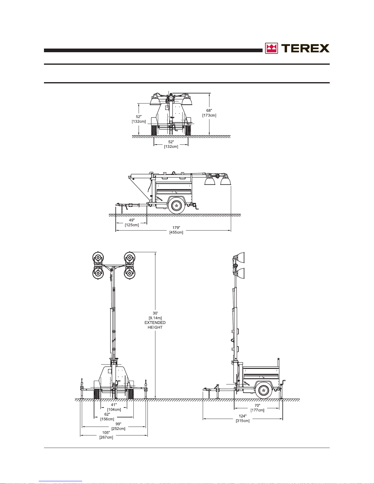
SPECIFICATIONS & DIMENSIONS
Part No. 833002 Rev A AL4000 Light Tower 25

November 2006
SPECIFICATIONS & DIMENSIONS
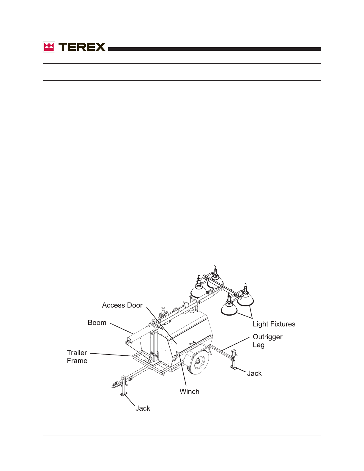
TEREX Amida model AL4000 series light tower provides mobile, trailer mounted floodlighting for
nighttime maintenance, construction, mining, and emergency work. It consists of a trailer with a
diesel powered 6 kW 60Hz (50 Hz units available) generator, and a 30 foot cable actuated tower
with four (4) 1000 watt floodlight fixtures. It is ideally suited for heavy-duty use and is built to
meet the following specification:
DIMENSIONS
Overall length, travel position w/fixtures & tongue 179” (4547 mm)
Overall length, tower vertical w/tongue & jacks 124” (3150 mm)
Trailer frame length 70” (1778 mm)
Overall height, floodlighting position 30’ (9114 mm)
Overall height, travel position 68” (1727 mm)
Overall width with fenders 62” (1575 mm)
Overall width with outriggers pulled out 105” (2667 mm)
Trailer frame width 41” (1041 mm)
Tongue length 49” (1245 mm)
Wheel size 15” (381mm)
Axle Rating 3500 lb. (1588 kg)
Tongue weight travel position 100 lb. (45.4 kg)
Total weight no fuel 2050 lb. (930 kg)
Fuel Capacity 30 gal. (114 kg)
Unit weight with full fuel tank 2250 lb. (1020 kg)
Max Highway Speed 60 mph (97 kmh)
NOISE LEVEL
Mean SPL (sound pressure level) hemispherically at 7 meters: 63dBA
Sound Power Level (63 dBA + 20 log d + 7.8): 90.0 LWA re 1 pW
D = 7 meters
DO NOT USE TOWER IN WIND SPEEDS ABOVE 62 MPH (100 KMH).
This section details specifications and maintenance not covered in the operators and troubleshooting sections of this manual and the AL4000 specification sheets.
BRAKE SYSTEM
Electrical or mechanical brakes are not standard equipment on the AL4000. Contact your dealer
or the factory for option information.
26 AL4000 Light Tower Part No. 833002 Rev A
 Loading...