

Terex AL4, AL4000 Service Manual
Discount-Equipment.com
Discount-Equipment.com is your online resource for commercial and industrial
Discount-Equipment.com
quality parts and equipment sales.
Locations:
Florida (West Palm Beach): 561-964-4949
Outside Florida TOLL FREE: 877-690-3101
Need parts? Check out our website at www.discount-equipment.com
Can’t find what you need?
Click on this link: http://www.discount-equipment.com/category/5443-parts/ and fill out
the request form.
Please have the machine model and serial number available in order to help us get
you the correct parts. One of our experienced staff members will get back to you with
a quote for the right part that your machine needs.
We sell worldwide for the brands: Genie, Terex, JLG, MultiQuip, Mayco, Toro/Stone,
Diamond Products, Magnum, Airman, Mustang, Power Blanket, Nifty Lift, Atlas Copco,
Chicago Pneumatic,
Tsurumi, Husquvarna/Target, Whiteman-Concrete/Mortar, Stow-Concrete/Mortar, Baldor,
Wacker, Sakai, Snorkel, Upright, Mi-T-M, Sullair, Neal, Basic, Dynapac, MBW, Weber,
Bartell, Bennar Newman, Haulotte, Ditch Runner, Blaw-Knox, Himoinsa, Best, Buddy,
Crown, Edco, Wyco, Bomag, Laymor, Terremite, Barreto, EZ Trench, Takeuchi, Basic, Bil-
Jax, Curtis, Gehl, Heli, Honda, ICS/PowerGrit, Puckett,
Clipper, MMD, Koshin, Rice, Gorman Rupp, CH&E, Cat Pumps, Comet, General Pump,
Giant,AMida, Coleman, NAC, Gradall, Square Shooter, Kent, Stanley, Tamco, Toku, Hatz,
Kohler, Robin, Wisconsin, Northrock, Oztec, Toker TK, Rol-Air, Small Line, Wanco, Yanmar
Allmand Brothers, Essick, Miller Spreader, Skyjack, Lull, Skytrak,
Waldon, ASV, IHI, Partner, Imer,
Introduction
Discount-Equipment.com
Introduction
Important
Read, understand and obey the safety rules and
operating instructions in the appropriate operator's
manual on your machine before attempting any
maintenance or repair procedure.
This manual provides detailed scheduled
maintenance information for the machine owner
and user. It also provides troubleshooting fault
codes and repair procedures for qualifi ed service
professionals.
Basic mechanical, hydraulic and electrical skills
are required to perform most procedures. However,
several procedures require specialized skills,
tools, lifting equipment and a suitable workshop.
In these instances, we strongly recommend that
maintenance and repair be performed at an
authorized Terex dealer service center.
August 2016
www.discount-equipment.com
Technical Publications
Terex has endeavored to deliver the highest
degree of accuracy possible. However, continuous
improvement of our products is a Terex policy.
Therefore, product specifi cations are subject to
change without notice.
Readers are encouraged to notify Terex of errors
and send in suggestions for improvement. All
communications will be carefully considered for
future printings of this and all other manuals.
Copyright © 2012 by Terex Corporation
218567 Rev B August 2016
First Edition, Second Printing
Terex is a registered trademarks of
Terex USA, LLC in the USA and many other
countries.
Printed on recycled paper
Printed in U.S.A.
AL4 • AL4000 Part No. 218567
ii
ii
August 2016
Discount-Equipment.com
Revision History
Revision Date Section Procedure / Schematic Page / Description
A 8/2012 New release
B 8/2016 Section 1 Updated revision history and serial number legend
REFERENCE EXAMPLES:
Kubota Engine_Section 2_Specifi cations.
A-6,B-3,C-7_Section 3_Maintenance Procedure.
3-2, 6-4, 9-1_Section 4_Repair Procedure.
Fault Codes_Section 5.
6-35, 6-56, 6-104_Section 6_Schematic Page #.
Part No. 218567 AL4 • AL4000
Click on any procedure or page number
highlighted in blue to view the update.
Electronic Version
iii

August 2016
Discount-Equipment.com
REVISION HISTORY
Revision Date Section Procedure / Schematic Page / Description
REFERENCE EXAMPLES:
Kubota Engine_Section 2_Specifi cations.
A-6,B-3,C-7_Section 3_Maintenance Procedure.
3-2, 6-4, 9-1_Section 4_Repair Procedure.
Fault Codes_Section 5.
6-35, 6-56, 6-104_Section 6_Schematic Page #.
AL4 • AL4000 Part No. 218567
iv
Click on any procedure or page number
highlighted in blue to view the update.
Electronic Version
August 2016
Discount-Equipment.com
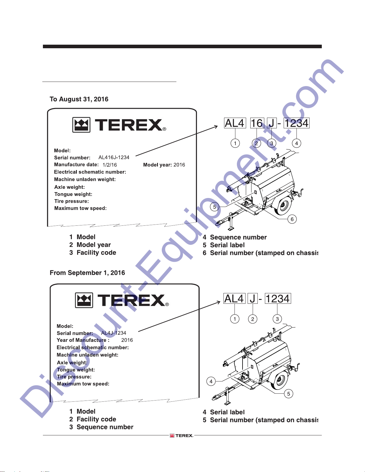
Serial Number Legend
INTRODUCTION
Part No. 218567 AL4 • AL4000
v
Section 1 • Safety Rules
Discount-Equipment.com
Safety Rules
Danger
Failure to obey the instructions and safety rules
in this manual, and the appropriate operator's
manual on your machine will result in death or
serious injury.
Many of the hazards identifi ed in the operator's
manual are also safety hazards when maintenance
and repair procedures are performed.
Do Not Perform Maintenance
Unless:
You are trained and qualifi ed to perform
maintenance on this machine.
You read, understand and obey:
- manufacturer’s instructions and safety rules
- employer’s safety rules and worksite
regulations
- applicable governmental regulations
You have the appropriate tools, lifting
equipment and a suitable workshop.
August 2016
Personal Safety
Any person working on or around a machine must
be aware of all known safety hazards. Personal
safety and the continued safe operation of the
machine should be your top priority.
Read each procedure thoroughly. This
manual and the decals on the machine,
use signal words to identify the following:
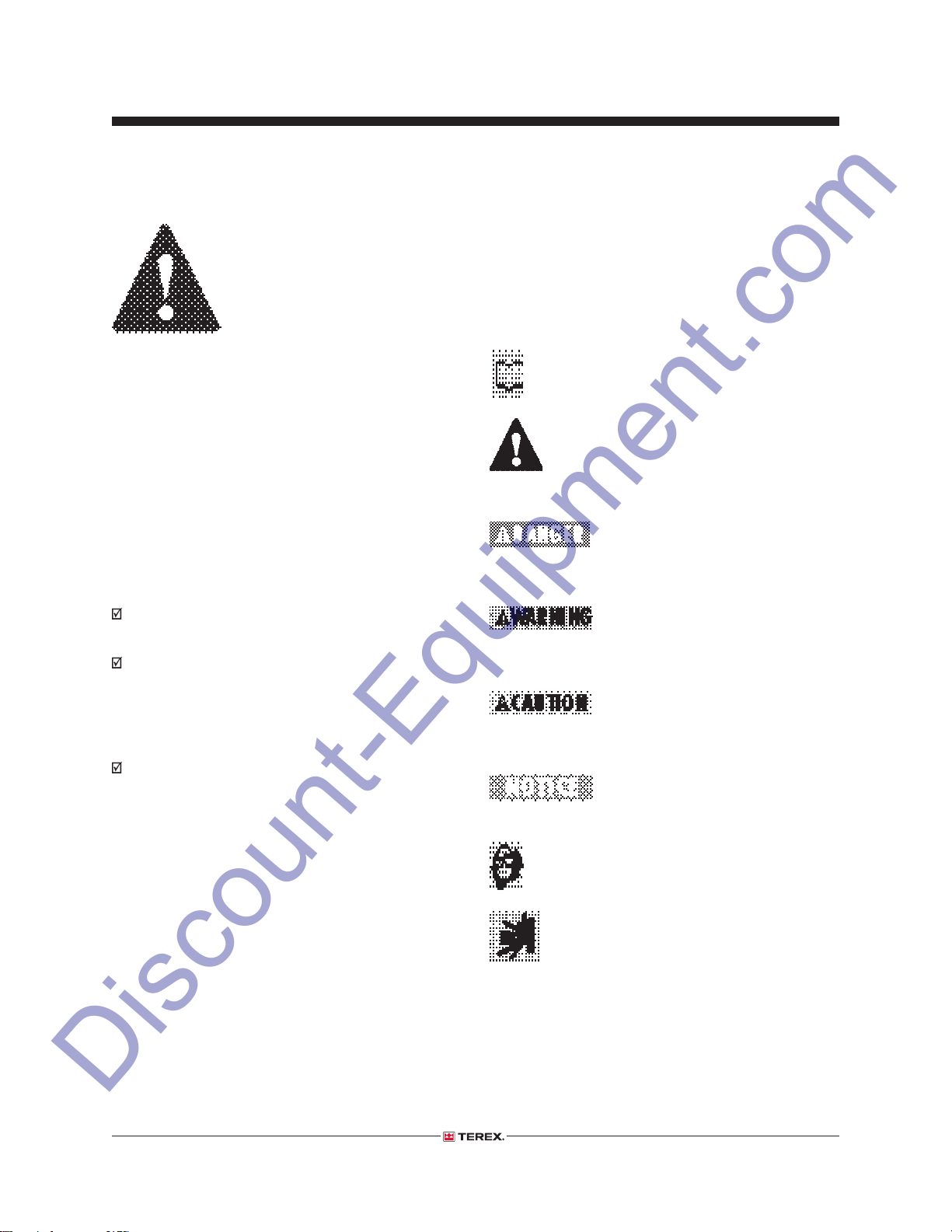
Safety alert symbol—used
to alert personnel to potential
personal injury hazards. Obey all
safety messages that follow this
symbol to avoid possible injury or
death.
Indicates an imminently
hazardous situation which, if not
avoided, will result in death or
serious injury.
Indicates a potentially hazardous
situation which, if not avoided,
could result in death or serious
injury.
Indicates a potentially hazardous
situation which, if not avoided,
may cause minor or moderate
injury.
Indicates a potentially hazardous
situation which, if not avoided,
may result in property damage.
Be sure to wear protective eye wear and
other protective clothing if the situation
warrants it.
Be aware of potential crushing hazards
such as moving parts, free swinging or
unsecured components when lifting or
placing loads. Always wear approved steel-toed
shoes.
AL4 • AL4000 Part No. 218567
vi
August 2016
Discount-Equipment.com
Workplace Safety
Be sure to keep sparks, fl ames and
lighted tobacco away from fl ammable
and combustible materials like battery
gases and engine fuels. Always have an
approved fi re extinguisher within easy reach.
Be sure that all tools and working areas
are properly maintained and ready for
use. Keep work surfaces clean and free
of debris that could get into machine
components and cause damage.
Be sure any forklift, overhead crane or
other lifting or supporting device is fully
capable of supporting and stabilizing
the weight to be lifted. Use only chains
or straps that are in good condition and of ample
capacity.
Section 1 • Safety Rules
SAFETY RULES
Be sure that fasteners intended for one
time use (i.e., cotter pins and self-locking
nuts) are not reused. These components
may fail if they are used a second time.
Be sure to properly dispose of old oil or
other fl uids. Use an approved container.
Please be environmentally safe.
Be sure that your workshop or work area
is properly ventilated and well lit.
Part No. 218567 AL4 • AL4000
vii
August 2016
Discount-Equipment.com
Table of Contents
Introduction
Important Information ................................................................................................... ii
Revision History .......................................................................................................... iii
Serial Number Legend ................................................................................................. v
Section 1 Safety Rules
General Safety Rules .................................................................................................. vi
Section 2 Specifi cations
Machine Specifi cations ...........................................................................................2 - 1
Performance Specifi cations .....................................................................................2 - 1
Generator Options ...................................................................................................2 - 2
Perkins 403D-11 Engine .........................................................................................2 - 2
Kubota D1105-D3BG Engine Specifi cations ...........................................................2 - 4
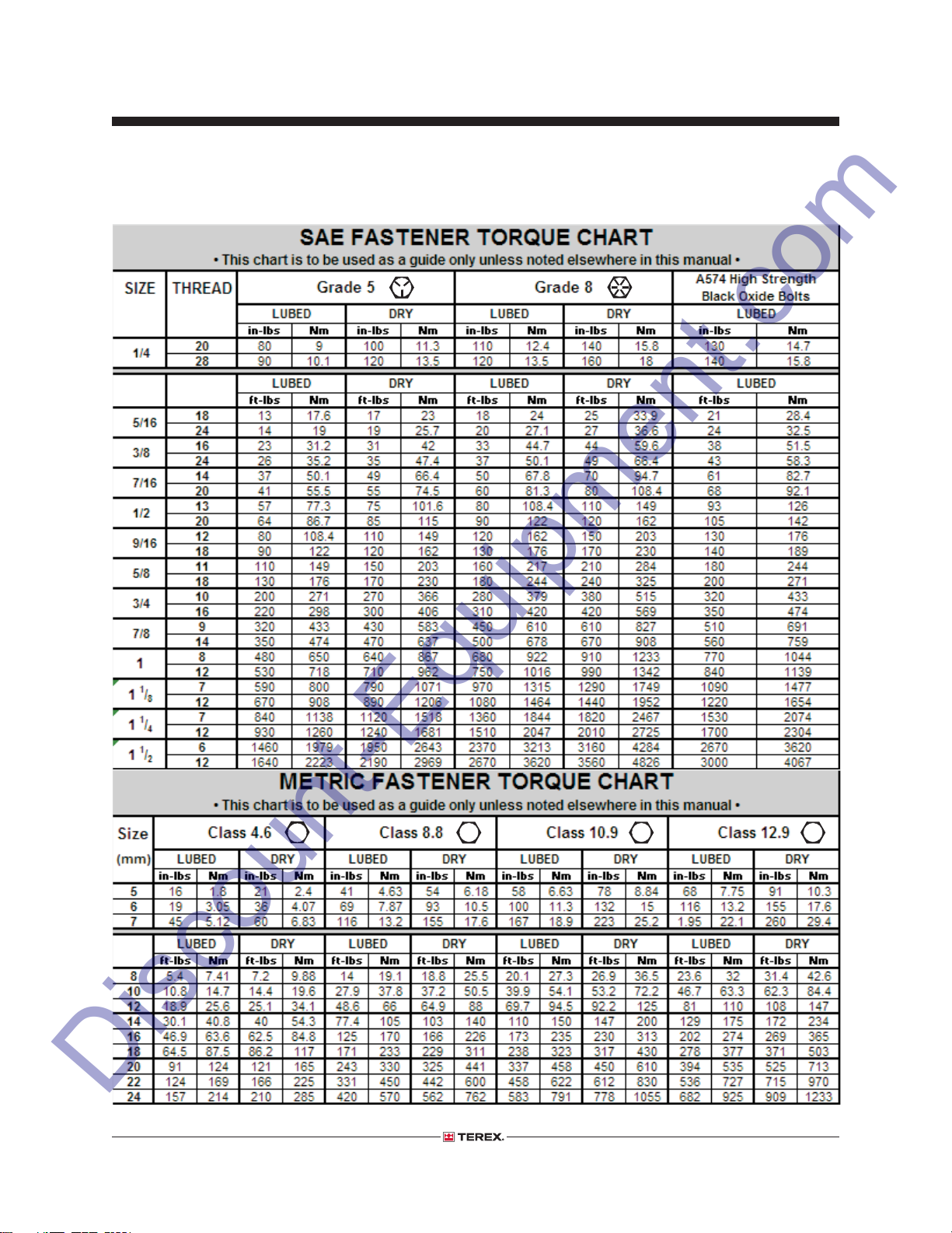
SAE and Metric Fasteners Torque Charts ...............................................................2 - 5
Section 3 Scheduled Maintenance Procedures
Introduction .............................................................................................................3 - 1
Maintenance Inspection Report ..............................................................................3 - 3
Checklist A Procedures
A-1 Inspect the Manuals and Decals ...................................................................3 - 5
A-2 Perform Pre-operation Inspection ..................................................................3 - 6
A-3 Perform Function Tests ..................................................................................3 - 6
Section 3 Scheduled Maintenance Procedures, continued
A-4 Perform Engine Maintenance ........................................................................3 - 7
A-5 Perform Coupler Maintenance .......................................................................3 - 7
AL4 • AL4000 Part No. 218567
viii
August 2016
Discount-Equipment.com
TABLE OF CONTENTS
A-6 Test the Brakes (if equipped) .........................................................................3 - 8
A-7 Torque the Wheel Lug Nuts ...........................................................................3 - 8
A-8 Check the Tires and Wheels ..........................................................................3 - 9
A-9 Inspect the Engine Air Filter ..........................................................................3 - 9
A-10 Perform Generator Maintenance - Leroy Somer Models .............................3 - 10
A-11 Perform Engine Maintenance - Kubota Models ...........................................3 - 10
A-12 Perform Engine Maintenance - Kubota Models ...........................................3 - 11
A-13 Inspect the Cable and Cable Pulleys ...........................................................3 - 11
A-14 Perform Engine Maintenance - Kubota Models ...........................................3 - 12
A-15 Perform Engine Maintenance - Kubota Models ...........................................3 - 13
A-16 Perform Generator Maintenance - Marathon Models ..................................3 - 13
A-17 Drain the Fuel Filter/Water Separator - Kubota Models ...............................3 - 14
A-18 Adjust the Brakes (if equipped) ...................................................................3 - 15
Checklist B Procedures
B-1 Inspect the Engine Start Battery or Lighting Battery Pack ..........................3 - 17
B-2 Inspect the Electrical Wiring ........................................................................3 - 18
B-3 Torque the Wheel Lug Nuts .........................................................................3 - 19
B-4 Perform Engine Maintenance - Perkins Models ..........................................3 - 19
B-5 Perform Jack Maintenance ..........................................................................3 - 20
B-6 Inspect and Lubricate the Winch .................................................................3 - 20
B-7 Lubricate the T-bolt ......................................................................................3 - 21
B-8 Inspect and Adjust the Brakes (if equipped) ................................................3 - 21
B-9 Inspect the Suspension ...............................................................................3 - 23
B-10 Perform Engine Maintenance - Kubota Models ...........................................3 - 24
Section 3 Scheduled Maintenance Procedures, continued
Checklist C Procedures
C-1 Perform Engine Maintenance ......................................................................3 - 25
C-2 Clean the Light Assemblies .........................................................................3 - 25
Part No. 218567 AL4 • AL4000
ix
August 2016
Discount-Equipment.com
TABLE OF CONTENTS
C-3 Grease the Wheel Bearings ........................................................................3 - 26
C-4 Inspect the Electric Brake Magnets (if equipped) ........................................3 - 27
C-5 Perform Engine Maintenance - Kubota Models ...........................................3 - 28
C-6 Perform Generator Maintenance - Leroy Somer Models .............................3 - 29
Checklist D Procedures
D-1 Perform Engine Maintenance - Kubota Models ...........................................3 - 30
D-2 Perform Generator Maintence - Leroy Somer Models .................................3 - 30
D-3 Perform Coupler Maintenance .....................................................................3 - 31
Checklist E Procedures
E-1 Replace the Mast Lift Cable ........................................................................3 - 32
E-2 Perform Engine Maintenance ......................................................................3 - 32
E-3 Perform Engine Maintenance ......................................................................3 - 33
E-4 Perform Generator Maintenance - Marathon Models ..................................3 - 33
E-5 Perform Generator Maintenance - Leroy Somer Models .............................3 - 34
E-6 Perform Generator Maintenance - Leroy Somer Models .............................3 - 34
Section 4 Repair Procedures
Introduction .............................................................................................................4 - 1
Mast
1-1 Mast ...............................................................................................................4 - 2
Winch
AL4 • AL4000 Part No. 218567
x
August 2016
Discount-Equipment.com
TABLE OF CONTENTS
2-1 Winch ............................................................................................................4 - 5
Generator
3-1 Generator ......................................................................................................4 - 8
Engine
4-1 Engine RPM ................................................................................................4 - 12
Section 5 Troubleshooting
Introduction .............................................................................................................5 - 1
Troubleshooting .......................................................................................................5 - 2
Section 6 Schematics
Introduction .............................................................................................................6 - 1
Wire Color Legend ..................................................................................................6 - 2
Trailer Lighting Wiring Diagram ...............................................................................6 - 3
Electrical Schematic, (ANSI / CSA) .........................................................................6 - 4
Electrical Schematic, (AUS) ....................................................................................6 - 5
Control Box and Engine Wiring, (Kubota Models) ...................................................6 - 8
Control Box and Engine Wiring, (Perkins Models) ..................................................6 - 9
Control Box and Engine Wiring, (AUS) ..................................................................6 - 12
Trailer Wiring Diagram, (ANSI / CSA) ....................................................................6 - 13
Trailer Wiring Diagram, (AUS) ...............................................................................6 - 15
Part No. 218567 AL4 • AL4000
xi

August 2016
Discount-Equipment.com
This page intentionally left blank.
AL4 • AL4000 Part No. 218567
xii
Section 2 • Specifi cationsAugust 2016
Discount-Equipment.com
Specifi cations
Machine Specifi cations
Total lighting wattage 4 x 1000 watts
Fuel capacities
Single tank 30 gallons
114 liters
Dual tanks (option) 60 gallons
227 liters
Tires and wheels
Tire size ST205/75D15
Load range C
Lug nut torque, dry 90 ft-lbs
122 Nm
Lug nut torque, lubricated 67.5 ft-lbs
91.5 Nm
Tire pressure, maximum (cold) 50 psi
3.4 bar
Performance Specifi cations
Tongue weight, maximum
With fuel (single tank) 150 lbs
68 kg
(dual tank) 130 lbs
59 kg
Run time
Single tank 50 hours
Continuous improvement of our products
For operational specifi cations, refer to the
Operator's Manual.
Part No. 218567 AL4 • AL4000 2 - 1
is a Genie policy. Product specifi cations are
subject to change without notice.

Section 2 • Specifi cations
Discount-Equipment.com
SPECIFICATIONS
August 2016
Generator Options 6 kw and 8 kw
Generator speed @ full load 60 Hz 1800 rpm
Temperature, ambient maximum 104°F
40°C
Capacitor (disconnected) 25 µF
7 kw
Generator speed @ full load 50 Hz 1500 rpm
Temperature, ambient maximum 104°F
40°C
Capacitor (disconnected) 25 µF
Perkins 403D-11 Engine
Displacement 68.9 cu in
1.1 liters
Number of cylinders 3
Bore and stroke 3.03 x 3.19 inches
77 x 81 mm
Horsepower, net intermittent 25 @ 3000 rpm
18.6 kW
Firing order 1 - 2 - 3
Compression ratio 23:1
Compression pressure 425 psi
29 bar
Pressure of the lowest cylinder must be within
50 psi / 3.5 bar of the highest cylinder, though
at no time less than 360 psi / 25 bar
Idle speed @ no load 1500 rpm
(with 7kw generator)
Frequency 50 hz
Idle speed @ no load 1800 rpm
(with 6kw or 8kw generator)
Frequency 60 hz
Governor centrifugal mechanical
Valve clearance, cold 0.0078 in
0.2 mm
Engine coolant capacity 2.0 quarts
1.9 liters
Engine coolant should be clean soft water with 50% anti
freeze concentration ethylene glycol to BS 6580:1992 or
ASTMD 3306-89 or AS 2108-1977
Continuous improvement of our products
is a Genie policy. Product specifi cations are
subject to change without notice.
2 - 2 AL4 • AL4000 Part No. 218567
Section 2 • Specifi cationsAugust 2016
Discount-Equipment.com
SPECIFICATIONS
Lubrication system
Oil pressure 40 to 60 psi
(hot @ 2000 rpm) 3 to 4 bar
Oil capacity (including fi lter) 4.6 quarts
4.4 liters
Oil viscosity requirements
Units ship with 15W-40.
Extreme operating temperatures may require the use of
alternative engine oils. For oil requirements, refer to the
Engine Operator Handbook on your machine.
Injection system
Injection pump make Bosch
Injection timing 23° BTDC @ 3000 rpm
Injection pump pressure 2133 psi
150 bar
Fuel requirement diesel number 2-D
Standard battery
Type 12V DC
Group 24
Quantity 1
Ampere hour 75 A
Cold cranking ampere 500
Reserve capacity @ 25A rate 65 minutes
Heavy duty battery
Type 12V DC
Group 24
Quantity 1
Ampere hour 75 A
Cold cranking ampere 700
Reserve capacity @ 25A rate 125 minutes
Alternator
Output 40A, 12V DC
Fan belt defl ection
5 mm
3
/
16
inch
Continuous improvement of our products
is a Genie policy. Product specifi cations are
subject to change without notice.
Part No. 218567 AL4 • AL4000 2 - 3
Section 2 • Specifi cations
Discount-Equipment.com
SPECIFICATIONS
August 2016
Kubota D1105-D3BG Engine
Displacement 68.53 cu in
1.123 liters
Number of cylinders 3
Bore and stroke 3.07 x 3.09 inches
78 x 78.4 mm
Horsepower, gross intermittent 13.6 @ 1800 rpm
10.1 kW
Firing order 1 - 2 - 3
Compression ratio 24:1
Compression pressure 412 to 469 psi
28.4 to 32.3 bar
Idle speed @ no load 1500 rpm
(with 7kw generator)
Frequency 50 hz
Idle speed @ no load 1800 rpm
(with 6kw or 8kw generator)
Frequency 60 hz
Governor centrifugal mechanical
Valve clearance, cold 0.0057 to 0.0072 in
0.145 to 0.185 mm
Engine coolant capacity 3.3 quarts
3.1 liters
Lubrication system
Oil pressure 28 to 64 psi
1.93 to 4.41 bar
Oil capacity (including fi lter) 5.4 quarts
5.1 liters
Injection timing 18° BTDC
Injection pump pressure 1991 psi
137 bar
Fuel requirement
For fuel requirements, refer to the engine Operator's
Manual on your machine.
Standard battery
Type 12V DC
Group 24
Quantity 1
Ampere hour 75 A
Cold cranking ampere 500
Reserve capacity @ 25A rate 65 minutes
Heavy duty battery
Type 12V DC
Group 24
Quantity 1
Ampere hour 75 A
Cold cranking ampere 700
Reserve capacity @ 25A rate 125 minutes
Alternator
Output 40A, 14V DC
Fan belt defl ection
7 to 9 mm
0.28 to 0.35 inch
Oil viscosity requirements
Units ship with 10W-30.
Extreme operating temperatures may require the use of
alternative engine oils. For oil requirements, refer to the
Engine Operator Handbook on your machine.
Injection system
Injection pump make Bosch MD
Continuous improvement of our products
is a Genie policy. Product specifi cations are
subject to change without notice.
2 - 4 AL4 • AL4000 Part No. 218567
Section 2 • Specifi cationsAugust 2016
Discount-Equipment.com
SPECIFICATIONS
4.6
Part No. 218567 AL4 • AL4000 2 - 5
10.9 12.98.8
Section 2 • Specifi cations
Discount-Equipment.com
August 2016
This page intentionally left blank.
2 - 6 AL4 • AL4000 Part No. 218567
Section 3 • Scheduled Maintenance ProceduresAugust 2016
DANGER
WARNING
CAUTION
NOTICE
Discount-Equipment.com
Scheduled Maintenance Procedures
About This Section
This section contains detailed procedures for each
scheduled maintenance inspection.
Each procedure includes a description, safety
warnings and step-by-step instructions.
Observe and Obey:
Maintenance inspections shall be completed
by a person trained and qualifi ed on the
maintenance of this machine.
Scheduled maintenance inspections shall
be completed daily, quarterly, semi-annually,
annually and every 2 years as specifi ed on the
Maintenance Inspection Report.
WARNING
Immediately tag and remove from service a
damaged or malfunctioning machine.
Repair any machine damage or malfunction
before operating the machine.
Use only Terex approved replacement parts.
Machines that have been out of service for a
period longer than 3 months must complete the
quarterly inspection.
Unless otherwise specifi ed, perform each
maintenance procedure with the machine in the
following confi guration:
• Machine parked on a fi rm, level surface
• Mast in the stowed position
• Wheels chocked
• Light switches in the off position
• No external AC power devices connected to
the power outlets at the control box.
Failure to perform each procedure
as presented and scheduled could
result in death, serious injury or
substantial damage.
Symbols Legend
Safety alert symbol—used to alert
personnel to potential personal
injury hazards. Obey all safety
messages that follow this symbol
to avoid possible injury or death.
Indicates an imminently
hazardous situation which, if not
avoided, will result in death or
serious injury.
Indicates a potentially hazardous
situation which, if not avoided,
could result in death or serious
injury.
Indicates a potentially hazardous
situation which, if not avoided,
may cause minor or moderate
injury.
Indicates a potentially hazardous
situation which, if not avoided,
may result in property damage.
Indicates that a specifi c result is expected after
performing a series of steps.
Indicates that an incorrect result has occurred
after performing a series of steps.
Part No. 218567 AL4 • AL4000 3 - 1
Section 3 • Scheduled Maintenance Procedures
Discount-Equipment.com
SCHEDULED MAINTENANCE PROCEDURES
August 2016
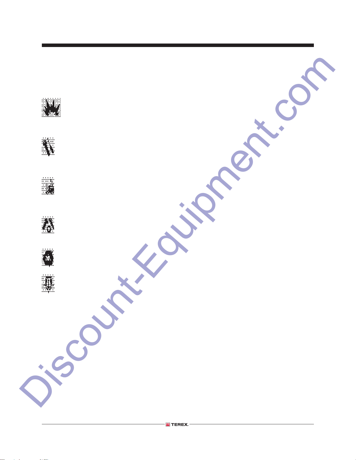
Maintenance Symbols Legend
Note: The following symbols have been used in
this manual to help communicate the intent of the
instructions. When one or more of the symbols
appears at the beginning of a maintenance
procedure, it conveys the meaning below.
Indicates that tools will be required to
perform this procedure.
Indicates that new parts will be required
to perform this procedure.
Indicates that a cold motor or pump will
be required to perform this procedure.
Indicates that dealer service will be
required to perform this procedure.
Maintenance Schedule
There are fi ve types of maintenance inspections
that must be performed according to a schedule—
daily, quarterly, semi-annually, annually, and
two year. The Scheduled Maintenance Procedures
Section and the Maintenance Inspection Report
have been divided into fi ve subsections—A, B,
C, D, and E. Use the following chart to determine
which group(s) of procedures are required to
perform a scheduled inspection.
Inspection Checklist
Daily or every 8 hours A
Quarterly or every 250 hours A + B
Semi-annually or every 500 hours A + B + C
Annually or every 1000 hours A + B + C + D
Two year or every 2000 hours A + B + C + D + E
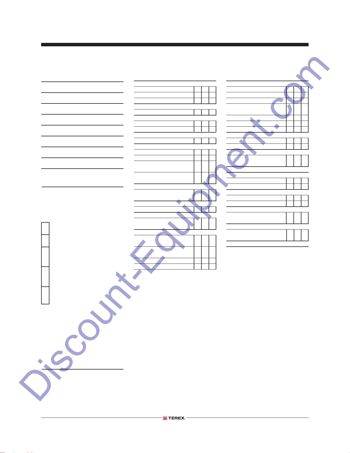
Maintenance Inspection Report
The maintenance inspection report contains
checklists for each type of scheduled inspection.
Make copies of the Maintenance Inspection Report
to use for each inspection. Maintain completed
forms in compliance with employer, job site and
governmental regulations.
3 - 2 AL4 • AL4000 Part No. 218567
Section 3 • Scheduled Maintenance ProceduresAugust 2016
Discount-Equipment.com
Maintenance Inspection Report
Model
Serial number
Date
Hour meter
Machine owner
Inspected by (print)
Inspector signature
Inspector title
Inspector company
Instructions
• Make copies of this report to use for
each inspection.
• Select the appropriate checklist(s) for
the type of inspection to be performed.
Daily or 8 hours
Inspection: A
Quarterly or 250 hours
Inspection: A+B
Semi-annually or
500 hours
Inspection: A+B+C
Annually or
1000 hours
Inspection: A+B+C+D
Two year or
2000 hours
Inspection: A+B+C+D+E
• Place a check in the appropriate box
after each inspection procedure is
completed.
• Use the step-by-step procedures in
this section to learn how to perform
these inspections.
• If any inspection receives an “N”, tag
and remove the machine from service,
repair and re-inspect it. After repair,
place a check in the “R” box.
Legend
Y = yes, acceptable
N = no, remove from service
R = repaired
Checklist A Y N R
A-1 Manuals and decals
A-2 Pre-operation inspect
A-3 Function tests
Perform every 8 hours:
A-4 Engine maintenance
Perform before towing:
A-5 Coupler
A-6 Brakes (if equipped)
Perform at 10 miles:
A-7 Lug nuts
Perform every week:
A-8 Tires and wheels
A-9 Engine air fi lter
A-10 Generator -
Leroy Somer Models
A-11 Engine maintenance -
Kubota models
Perform after 50 hours:
A-12 Engine maintenance -
Kubota models
Perform every month:
A-13 Cable and Pulleys
Perform every 100 hours:
A-14 Engine maintenance -
Kubota models
Perform every 200 hours:
A-15 Engine maintenance -
Kubota models
A-16 Generator
Marathon Models
A-17 Fuel/Water Separator
A-18 Brakes (if equipped)
Checklist B Y N R
B-1 Battery
B-2 Electrical wiring
B-3 Lug nuts
B-4 Engine maintenance -
Perkins models
B-5 Jack
B-6 Winch
B-7 T-bolt
Perform every 3000 miles:
B-8 Brakes (if equipped)
B-9 Suspension
Perform every 400 hours:
B-10 Engine maintenance -
Kubota models
Checklist C Y N R
C-1 Engine maintenance
C-2 Lights
Perform every 6000 miles:
C-3 Wheel bearings
C-4 Brakes (if equipped)
Perform every 800 hours:
C-5 Engine maintenance -
Kubota models
Perform every 2000 hours:
C-6 Generator -
Leroy Somer Models
Comments
Part No. 218567 AL4 • AL4000 3 - 3
Section 3 • Scheduled Maintenance Procedures
Discount-Equipment.com
MAINTENANCE INSPECTION REPORT
August 2016
Model
Serial number
Date
Hour meter
Machine owner
Inspected by (print)
Inspector signature
Inspector title
Inspector company
Instructions
• Make copies of this report to use for
each inspection.
• Select the appropriate checklist(s) for
the type of inspection to be performed.
Daily or 8 hours
Inspection: A
Quarterly or 250 hours
Inspection: A+B
Semi-annually or
500 hours
Inspection: A+B+C
Annually or
1000 hours
Inspection: A+B+C+D
Two year or
2000 hours
Inspection: A+B+C+D+E
• Place a check in the appropriate box
after each inspection procedure is
completed.
• Use the step-by-step procedures in
this section to learn how to perform
these inspections.
• If any inspection receives an “N”, tag
and remove the machine from service,
repair and re-inspect it. After repair,
place a check in the “R” box.
Legend
Y = yes, acceptable
N = no, remove from service
R = repaired
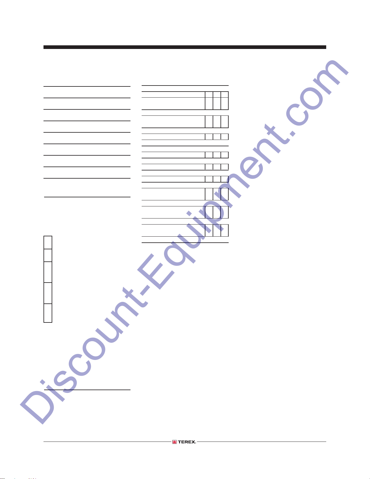
Checklist D Y N R
Perform every 1500 hours:
D-1 Engine maintenance -
Kubota models
Perform every 8000 hours:
D-2 Generator -
Leroy Somer Models
Perform annually:
D-3 Coupler
Checklist E Y N R
E-1 Cable
Perform every 2000 hours:
E-2 Engine maintenance
Perform every 3000 hours:
E-3 Engine maintenance
Perform every 10,000 hours:
E-4 Generator -
Marathon Models
Perform every 20,000 hours:
E-5 Generator -
Leroy Somer Models
Perform every 30,000 hours:
E-6 Generator -
Leroy Somer Models
Comments
3 - 4 AL4 • AL4000 Part No. 218567
Section 3 • Scheduled Maintenance ProceduresAugust 2016
Discount-Equipment.com
Checklist A Procedures
A-1
Inspect the Manuals and Decals
Terex specifi cations require that this procedure be
performed at the beginning of every work shift or
daily, whichever comes fi rst.
Maintaining the operator’s and safety manuals
in good condition is essential to safe machine
operation. Manuals are included with each
machine and should be stored in the container
provided in the cabinet. An illegible or missing
manual will not provide safety and operational
information necessary for a safe operating
condition.
In addition, maintaining all of the safety and
instructional decals in good condition is mandatory
for safe machine operation. Decals alert operators
and personnel to the many possible hazards
associated with using this machine. They also
provide users with operation and maintenance
information. An illegible decal will fail to alert
personnel of a procedure or hazard and could
result in unsafe operating conditions.
replaced.
3 Open the operator's manual to the decals
inspection section. Carefully and thoroughly
inspect all decals on the machine for legibility
and damage.
Result: The machine is equipped with all
required decals, and all decals are legible and
in good condition.
Result: The machine is not equipped with all
required decals, or one or more decals are
illegible or in poor condition. Remove the
machine from service until the decals are
replaced.
4 Always return the manuals to the storage
container after use.
Note: Contact your authorized Terex distributor
or Terex if replacement manuals or decals are
needed.
1 Check to make sure that the operator's and
safety manuals are present and complete in the
storage container in the cabinet.
2 Examine the pages of each manual to be sure
that they are legible and in good condition.
Result: The operator's manual is appropriate for
the machine and all manuals are legible and in
good condition.
Result: The operator's manual is not
appropriate for the machine or all manuals are
not in good condition or is illegible. Remove
the machine from service until the manual is
Part No. 218567 AL4 • AL4000 3 - 5
Section 3 • Scheduled Maintenance Procedures
Discount-Equipment.com
CHECKLIST A PROCEDURES
August 2016
A-2
Perform Pre-operation Inspection
Terex specifi cations require that this procedure be
performed at the beginning of every work shift or
daily, whichever comes fi rst.
Completing a Pre-operation Inspection is essential
to safe machine operation. The Pre-operation
Inspection is a visual inspection performed by the
operator prior to each work shift. The inspection
is designed to discover if anything is apparently
wrong with a machine before the operator
performs the function tests. The Pre-operation
Inspection also serves to determine if routine
maintenance procedures are required.
Complete information to perform this procedure
is available in the appropriate operator's manual.
Refer to the Operator's Manual on your machine.
A-3
Perform Function Tests
Terex specifi cations require that this procedure be
performed at the beginning of every work shift or
daily, whichever comes fi rst.
Completing the function tests is essential to safe
machine operation. Function tests are designed to
discover any malfunctions before the machine is
put into service. A malfunctioning machine must
never be used. If malfunctions are discovered,
the machine must be tagged and removed from
service.
Complete information to perform this procedure
is available in the appropriate operator's manual.
Refer to the Operator's Manual on your machine.
3 - 6 AL4 • AL4000 Part No. 218567

Section 3 • Scheduled Maintenance ProceduresAugust 2016
Discount-Equipment.com
CHECKLIST A PROCEDURES
A-4
Perform Engine Maintenance
Engine specifi cations require that this procedure
be performed every 8 hours or daily, whichever
comes fi rst.
• Check oil level
• Check radiator level
• Oil or coolant leaks
• Loose or missing fasteners
Required maintenance procedures and additional
engine information is available in the
Kubota D1105 Operator's Manual
(Kubota part number 16622-89166) OR the
Perkins 403D-11 User's Handbook
(Perkins part number SEBU8311-01)
Kubota D1105 Operator's Manual
Genie part number 131379
Perkins 403D-11 User's Handbook
Genie part number 131661
A-5
Perform Coupler Maintenance
Coupler specifi cations require that this procedure
be performed before towing.
Maintaining the coupler in good condition is
essential to safe operation and good performance.
Coupler failure could result in a machine tip-over
during transport, and component damage may
also result if problems are not discovered and
repaired in a timely fashion.
1 Check vehicle, mounting bracket, hitch ball and
coupler for signs of wear or damage and that
the coupler handle opens and closes freely.
Result: If coupler and/or mounting bracket
is deformed or damaged, replace complete
coupler and mounting bracket. Replace bent,
broken or worn parts before use.
2 Close coupler securely by ensuring that the
hitch ball is fully seated in the coupler ball
pocket and the pin is inserted behind the collar
or latch.
3 Check mounting bracket hardware for wear and
proper tightness.
Result: Replace bent, broken or worn hardware.
Part No. 218567 AL4 • AL4000 3 - 7
Section 3 • Scheduled Maintenance Procedures
Discount-Equipment.com
CHECKLIST A PROCEDURES
August 2016
A-6
Test the Brakes (if equipped)
Axle specifi cations require that this procedure be
performed before towing.
Maintaining the axle brakes in good condition is
essential to safe operation and good performance.
Brakes which are out of adjustment can result in
longer stopping distances and excessive brake
wear on the towing vehicle. Component damage
may also result if problems are not discovered and
repaired in a timely fashion.
1 Test the brakes for proper function. Repair or
replace any faulty components as needed.
A-7
Torque the Wheel Lug Nuts
Axle specifi cations require that this procedure be
performed initially at 10, 25 and 50 miles of use, or
after reinstallation of a tire.
Maintaining the wheel lug nuts at the proper torque
is essential to safe operation and good service life
of the tires, wheel and axle.
1 Check each lug nut for proper torque.
Specifi cation
Lug nut torque, dry 90 ft-lbs
122 Nm
Lug nut torque, lubricated 67.5 ft-lbs
91.5 Nm
3 - 8 AL4 • AL4000 Part No. 218567
 Loading...