

Page 1

Operating Manual
Page 2

Table of contents
Table of contents
1 Before you get started… .................................................................. 4
1.1 Intended use ....................................................................................... 4
1.2 What do the symbols used here mean? ............................................. 4
2 For your safety .................................................................................. 6
2.1 General safety information ................................................................. 6
2.2 About laser beams .............................................................................. 7
2.3 Workplace safety ................................................................................ 7
2.4 Electrical safety .................................................................................. 7
2.5 About strong magnets ........................................................................ 8
2.6 Human safety ..................................................................................... 8
2.7 Service ................................................................................................ 9
2.8 Special instructions concerning the device ........................................ 9
3 Description of product ................................................................... 11
3.1 Scope of delivery .............................................................................. 11
3.2 Your device at a glance .................................................................... 12
4 First operation ................................................................................ 14
4.1 Connection........................................................................................ 14
4.2 Connection of a LAP-TEQ Sensor PLUS (optional) ......................... 17
4.3 Fastening the magnetic mounting bracket ....................................... 18
5 Operation ......................................................................................... 19
5.1 Power on/off ..................................................................................... 19
2 V-11/2018
Page 3

Table of contents
6 Trigonometric correction / length unit ......................................... 20
7 Cleaning and care........................................................................... 22
8 Malfunctions and troubleshooting ............................................... 23
8.1 Service centre ................................................................................... 24
8.2 Observe ambient conditions ............................................................. 25
9 Storage ............................................................................................ 26
10 Disposal ........................................................................................... 27
11 Technical data ................................................................................. 28
12 Declaration of Conformity ............................................................. 29
LAP-TEQ Elevation 3
Page 4
Before you get started…
1 Before you get started…
1.1 Intended use
The LAP-TEQ Elevation Sensor is designed to determine the correct mounting
height for speakers.
The LAP-TEQ Elevation Sensor measures the vertical distance between the
unit and the surface directly beneath. The measured distance is displayed on a
LAP-TEQ Display PLUS or a LAP-TEQ Motion System, to be purchased
separately.
Any other use not described in this operating manual is unauthorised misuse.
The manufacturer will not be liable for damages incurred from such misuse.
Never use the device in public transport (road traffic, aviation, etc.).
1.2 What do the symbols used here mean?
Danger notices and warnings are clearly designated in the operating manual.
The following symbols are used:
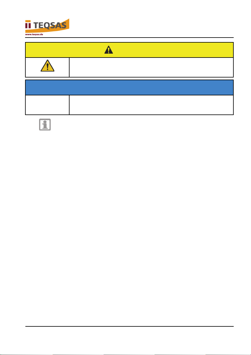
Danger!
Immediate danger of death or injury!
Immediately dangerous situation that will result in death or
severe injuries.
Warning!
Probable danger of death or injury!
4 V-11/2018
Generally dangerous situation that can result in death or
severe injuries.
Page 5
Before you get started…
Caution!
Potential danger of injury!
Dangerous situation that can result in injuries.
Attention!
Danger of damage to device!
Situation that can result in material damage.
Notice
Information provided for better understanding of the processes.
LAP-TEQ Elevation 5
Page 6
For your safety
2 For your safety
Warning!
Failure to comply with the safety information and
2.1 General safety information
Store all safety information and instructions for future reference. The term
device used in the safety information refers to mains-powered devices
(with a mains cable) and to battery-powered devices (without a mains
cable).
Danger of death and accident for small children and children! Never leave
children unattended with the packaging material and the product. There is
a danger of suffocation from the packaging material and danger of death
from strangulation. Children often underestimate dangers. Always keep
children away from the product. The product is not a toy.
For safe use of this device the user of the device must have read and
understand this operating manual prior to the first use of the device.
If you sell or pass on the device, be sure to include this operating manual
with the device.
This device is not intended for use by persons (including children) with
impaired physical, sensory or mental capacities or insufficient experience
and/or insufficient knowledge, unless they are supervised by a person who
is responsible for their safety or receive instructions from that person on
how to use the device.
The device may be used only if it is in perfect working order and
completely mounted. If the device or a component thereof is defective, it
must be taken out of operation and repaired by a specialist or properly
disposed of.
instructions can cause electric shock, fire and/or
severe injuries.
► Read all safety information and instructions.
6 V-11/2018
Page 7

For your safety
Use the device only for the purpose for which it is intended.
Keep children away from the device! Store the device safely out of the
reach of children and unauthorised persons.
Use and store the device only within the permissible ambient conditions
(temperatures, humidity, etc.).
2.2 About laser beams
Do not look into the beam, even at large distances.
Never point the measuring beam at people, other living beings or reflective
surfaces.
Commercially available laser glasses do not provide protection against the
dangers of laser beams. They only help to better recognise the laser
beam.
2.3 Workplace safety
Keep your workplace clean and well lighted. Disorder and unlighted
workplaces can cause accidents.
Observe the applicable workplace and accident prevention regulations for
your country.
Do not use the electrical device in potentially explosive environments
containing flammable liquids, gases or dusts. Electric tools generate
sparks, which can ignite dust or vapours.
2.4 Electrical safety
In dry environments it is possible for static electricity to occur. In dry
rooms, touch a metal object to discharge static electricity before operating
the device.
Do not misuse the cables to carry or suspend the device or to pull the plug
from the electrical outlet. Keep cables away from heat, oil, sharp edges or
moving device components. Damaged or tangled cables increase the risk
of damage to the device.
If you use the device outdoors, use only extension cables that are suitable
for outdoor use. The use of an extension cable that is suitable for outdoor
use reduces the risk of damage to the device.
LAP-TEQ Elevation 7
Page 8

For your safety
2.5 About strong magnets
Magnets can affect the functioning of pacemakers and implanted
defibrillators. If you wear one of these devices, stay out of the direct
vicinity of the magnets!
The holding force of magnets can weaken. Be aware at all times that a
magnet can become demagnetised, causing the unit to fall. The unit and
mounting brackets must therefore always be secured with arrester cables!
Magnets have a strong magnetic force. When handling magnets, be
careful that they do not pinch your fingers or skin. Wear safety gloves, if
necessary.
Magnets are brittle and can crack or shatter. Avoid magnets striking each
other or hard surfaces. Do not expose them to mechanical stress such as
drilling or grinding.
Magnets and their coatings can contain nickel. Regular contact with them
can trigger nickel allergies. Avoid contact between magnets and bare skin.
In persons with a nickel allergy, contact can cause allergic reactions. If you
have a nickel allergy, you should not handle magnets.
The magnetic field of a magnet can cause irreversible damage to objects.
Maintain a sufficient safety distance of at least 1 metre. Objects that can
be damaged include, for example:
- electronic devices such as hearing aids, laptops and monitors
- objects that contain iron, such as mechanical watches
- data carriers such as magnetic strips on credit cards, hard drives, etc.
2.6 Human safety
Be attentive, pay attention to what you are doing, and use common sense
while working. Do not use the device if you are tired or under the influence
of drugs, alcohol or medications. One moment of carelessness during use
of the device can result in serious injuries. The sensor and the magnetic
mounting bracket must be secured against falling by suitable means.
8 V-11/2018
Page 9

For your safety
2.7 Service
Have your device repaired only by qualified specialists, and only using
original replacement parts. This will ensure the long-term safety of the
electric tool.
Provide for adequate lighting when working with the device. Poor visibility
can increase the risk of accidents.
Use only accessories that are intended especially for use with this device
and recommended by the manufacturer. The fact that you can attach
accessories to the device is no guarantee for their safe and trouble-free
use.
The device can show signs of wear over time.
The use of non-approved accessories can result in damage or wear that is
not covered by the warranty.
2.8 Special instructions concerning the device
Do not use the device in potentially explosive areas or in the vicinity of
flammable liquids or gases!
Paint and labels can cause moving parts to stick, therefore impairing
correct operation.
If you are have an allergic reaction to the paint or metal parts of the
device, the result may be itching, eczemas or swelling of the skin. If this is
the case, discontinue using the device and consult a physician.
Broken glass or plastic can cause injuries. Have the device repaired in the
service centre.
Do not allow the device to fall or expose it to shocks.
The device or parts of it can become damaged from falling, bending or
deformation.
The device features safeguards to limit the emitted laser beam: Do not
make any modifications to the optical system.
This device is classified as a class 2 laser product in accordance with the
international standard IEC 60825. It operates with a visible laser beam,
which is not dangerous in normal operation.
Do not remove or cover symbols located on your device. Illegible
information must be replaced immediately.
LAP-TEQ Elevation 9
Page 10

For your safety
Read and comply with the operating manual prior to operating the
device.
Danger of eye injuries!
Never look directly into the laser beam.
10 V-11/2018
Page 11
3 Description of product
3.1 Scope of delivery
Description of product
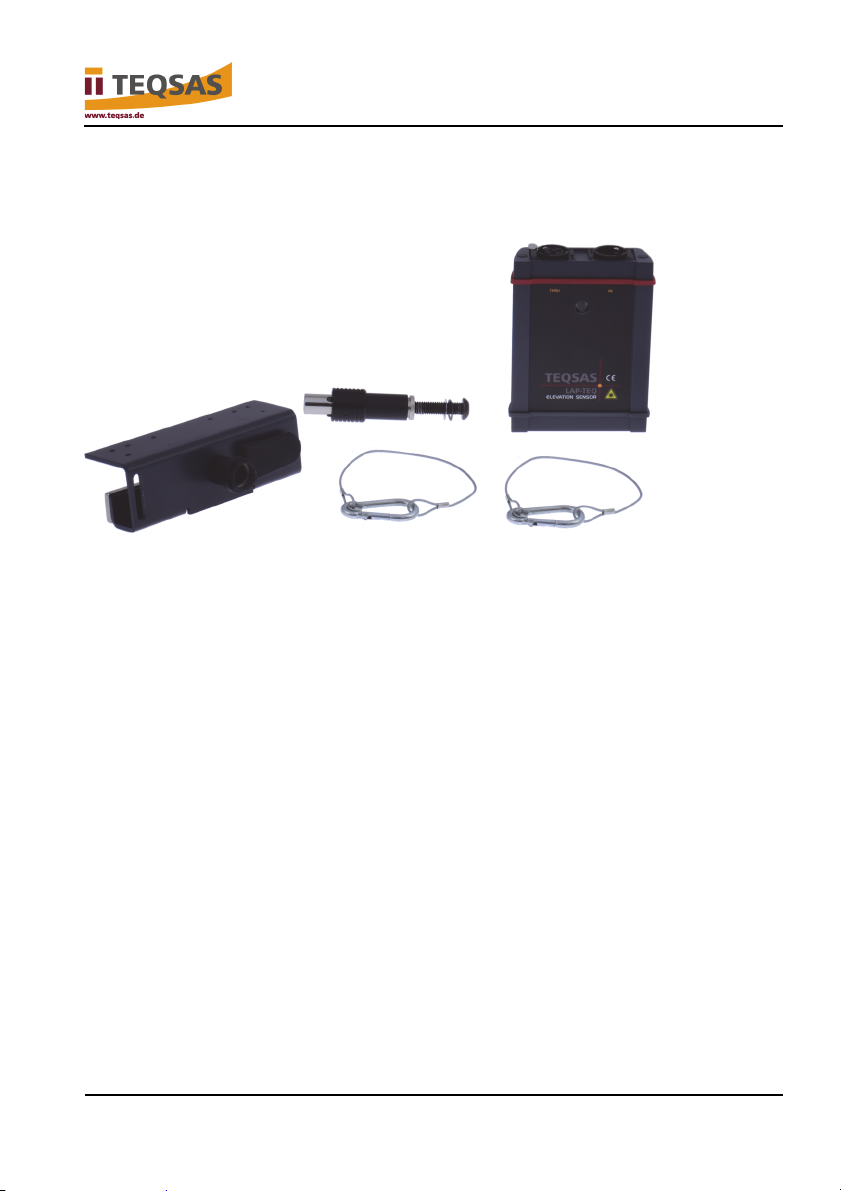
The standard set includes the following components:
2x: LAP-TEQ Elevation
2x: LAP-TEQ mounting bracket (magnetic)
2x: Mechanical quick-release connector (already mounted on the unit and
on the mounting bracket at time of delivery)
4x: Arrester cable
1x: Safety data sheet
1x: Transport case
Of course, all components can also be ordered separately.
LAP-TEQ Elevation 11
Page 12
Description of product
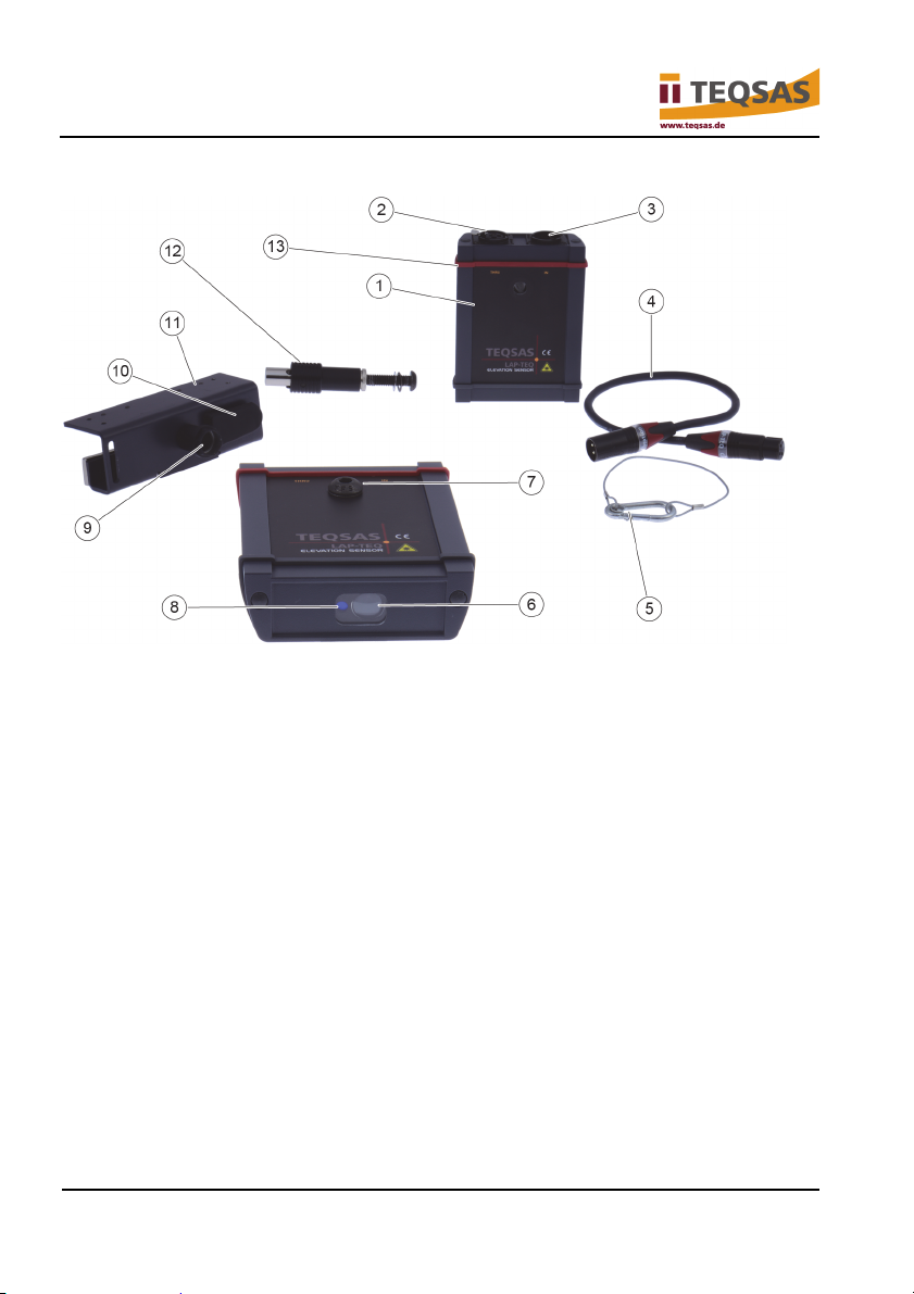
3.2 Your device at a glance
1. LAP-TEQ Elevation Sensor
2. Socket for XLR cable (for LAP-TEQ Sensor PLUS (optional))
3. Socket for XLR cable (to display unit)
4. XLR cable for display unit / LAP-TEQ Sensor PLUS (not included)
5. Arrester cable
6. Measuring optic
7. Holder for mechanical quick-release connector
8. Laser beam output
9. Holder for mechanical quick-release connector
10. Strain relief for XLR cable to display unit (or for XLR cable to LAP-TEQ
Sensor PLUS)
11. LAP-TEQ mounting bracket (magnetic)
12. Mechanical quick-release connector with swivel joint (already mounted on
unit at time of delivery)
13. The reference level for the height measurement is the RED bumper (zero
line).
12 V-11/2018
Page 13

Description of product
Notice
In the factory setting, the trigonometric correction is activated
and unit is set to “m” (metres). To deactivate the trigonometric
correction and/or to change the unit to “ft” (feet), refer to
“Trigonometric correction / length unit” on page 20 and follow
the instru
ctions provided there.
A complete LAP-TEQ Elevation distance measuring system consists of an
elevation unit mounted on a magnetic mount and a connected display system
such as LAP-TEQ Display PLUS or LAP-TEQ Motion System.
The elevation unit is designed for mounting on a flying frame, for example, and
measures the vertical distance between the zero line on the unit (see Your
device at a gl
ance on page 12 ) and the surface beneath. This provides
information on the height of the speaker element and/or of the entire array.
The laser beam of the elevation unit is used for visually checking the area of
the surface to which the measurement is made. This allows you to determine
whether the end point of the measurement is correct.
The magnetic mounting bracket can also be used to mount a LAP-TEQ Sensor
PLUS. It is then possible to simultaneously measure the height and the vertical
alignment. Both values are shown simultaneously on the display. Use of a
LAP-TEQ Motion System as the display unit allows simultaneous adjustment
of the height and alignment.
LAP-TEQ Elevation 13
Page 14
First operation
4 First operation
4.1 Connection
Danger of damage to device!
Moisture and liquids can damage the components or
electronic circuits in the device.
► Do not switch the device on if it is damp.
► If the device is already switched on, switch it off.
► If the device cannot be switched off, allow it to dry in
this state.
► Dry the device with a dry cloth and take it to the service
centre.
Danger of damage to device
► All components are maintenance free. Never open the
device; otherwise, the warranty will be voided. The only
exception is opening the lower cover to set the
measuring unit and the correction mode.
Attention!
Attention!
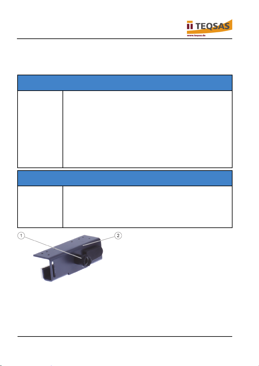
► If not already mounted, screw the sleeve of the mechanical quick-release
connector (1) into the magnetic mounting bracket (2).
14 V-11/2018
Page 15
First operation
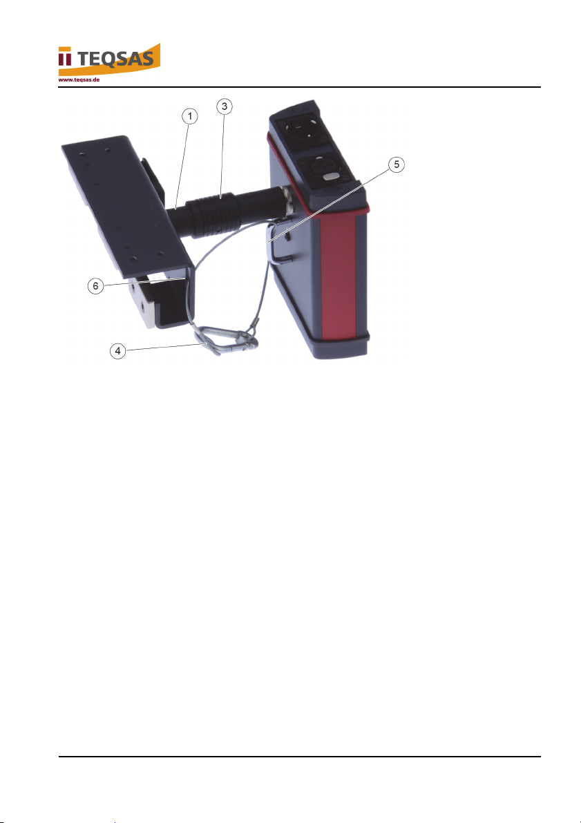
► Pull the ring (3) on the mechanical quick-release connector and press the
quick-release connector into the sleeve (1) of the magnetic mounting
bracket.
► Insert the arrester cable (4) through the safety shackle (5) and the slot (6)
on the magnetic mounting bracket.
► Connect the snap hook of the arrester cable (4) to the loop.
LAP-TEQ Elevation 15
Page 16
First operation
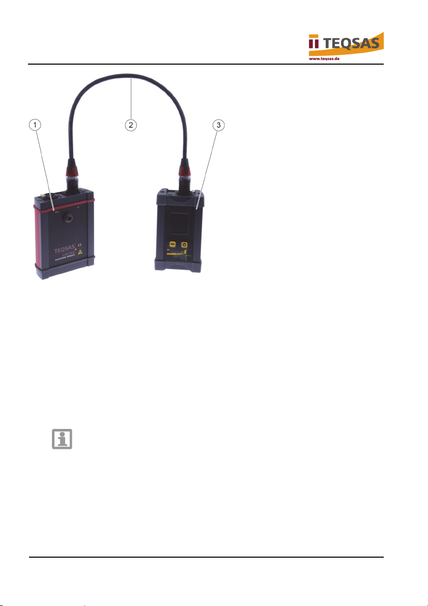
► Connect the elevation unit (1) to the input “IN”, and the display unit (3)
using a standard 3-pin XLR cable (2).
There is no limit to the number of elevation units that can be connected
successively to a display unit. For example, three elevation units can be used
to check the correct orientation of a left and right PA system, as well as a
centre cluster.
To function correctly, the display unit must be connected to a elevation unit
using a standard XLR connection cable. The elevation unit is supplied with
power by means of the XLR cable. There are no rechargeable batteries or
other batteries in the elevation unit.
Notice
The length of the cable (2) between the display unit and the
elevation unit must not exceed 70 m.
For a distance greater than 70 m, you must use an XLR cable
with a larger cross section than 0.22 mm². This will reduce the
16 V-11/2018
voltage drop along the cable route.
Page 17
First operation
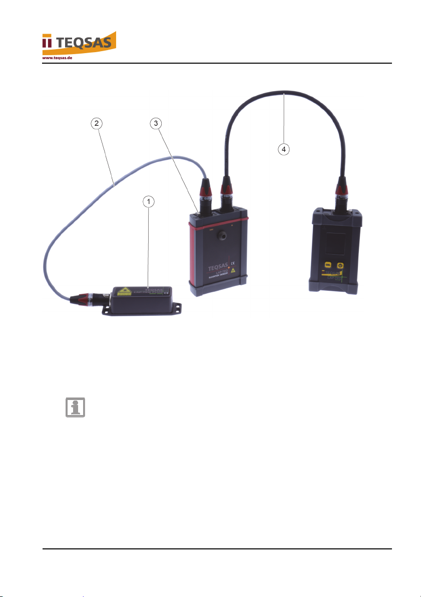
4.2 Connection of a LAP-TEQ Sensor PLUS (optional)
► Mount the LAP-TEQ Sensor PLUS (1) likewise on the flying frame of the
magnetic mounting bracket (see operating instructions for LAP-TEQ
PLUS).
► Connect the LAP-TEQ Sensor PLUS (1) to the “THRU” socket of the
elevation unit (3) by means of a standard 3-pin XLR cable (2).
Notice
The entire length of the cables (2) + (4) between the LAP-TEQ
Sensor PLUS, the elevation unit and the display unit must not
exceed 45 m.
For a distance greater than 45 m, you must use an XLR cable
with a larger cross section than 0.22 mm². This will reduce the
LAP-TEQ Elevation 17
voltage drop along the cable route.
Page 18
First operation
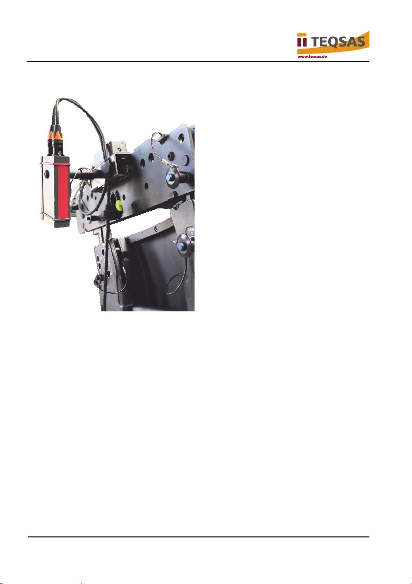
4.3 Fastening the magnetic mounting bracket
► Place the magnetic mounting bracket on the upper edge of the flying
frame.
► Use the arrester cable to secure the magnetic mounting bracket on the
flying frame against falling down.
► Insert the XLR cable in a loop through the strain relief on the magnetic
mounting bracket.
► Check to ensure that the elevation unit can stabilise freely.
► Make sure that there are no objects in the measuring path. This could
result in incorrect measurements.
18 V-11/2018
Page 19
Operation
5 Operation
5.1 Power on/off
Notice
Make sure that the reference point for the measurement is
correct. If the deviation to perpendicular is so large that the
laser detects an object, for example, this will result in an
Check the condition of the device:
► Check for visible defects.
► Check to make sure that all parts of the device are firmly mounted.
incorrect measurement.
Warning!
Danger of eye injuries from laser beams!
► Make sure that no one is within the effective range of the laser.
► Power on: Press the “Power” button on the display unit for about 3
seconds.
If the system has started up correctly, the red laser lights up and the current
distance is displayed. If a LAP-TEQ Sensor PLUS is connected in addition, the
current angle reading will be displayed simultaneously.
The measurement is refreshed continuously; in unfavourable conditions (cp.
Observe ambient conditions on page 25
► Power off: Press the “Power” button on the display unit again.
If the laser beam hits the eyes via optical devices, this can
result in irreparable damage.
► Never look into the laser or direct the laser beam onto
reflecting surfaces!
) this can take up to 3 seconds.
LAP-TEQ Elevation 19
Page 20
Trigonometric correction / length unit
6 Trigonometric correction / length unit
Notice
In the factory setting, the length unit is set to “m” (metres). It can
If the elevation unit cannot stabilise freely (e.g. due to cable tension), the
trigonometric correction can correct the deviation.
If the trigonometric correction is activated, a deviation from perpendicular is
corrected. The corrected value is shown on the display. If it is deactivated, the
actual reading of the crooked measurement, which could be incorrect, will be
displayed.
be changed to “ft” (feet).
Notice
In the factory setting, the trigonometric correction is activated.
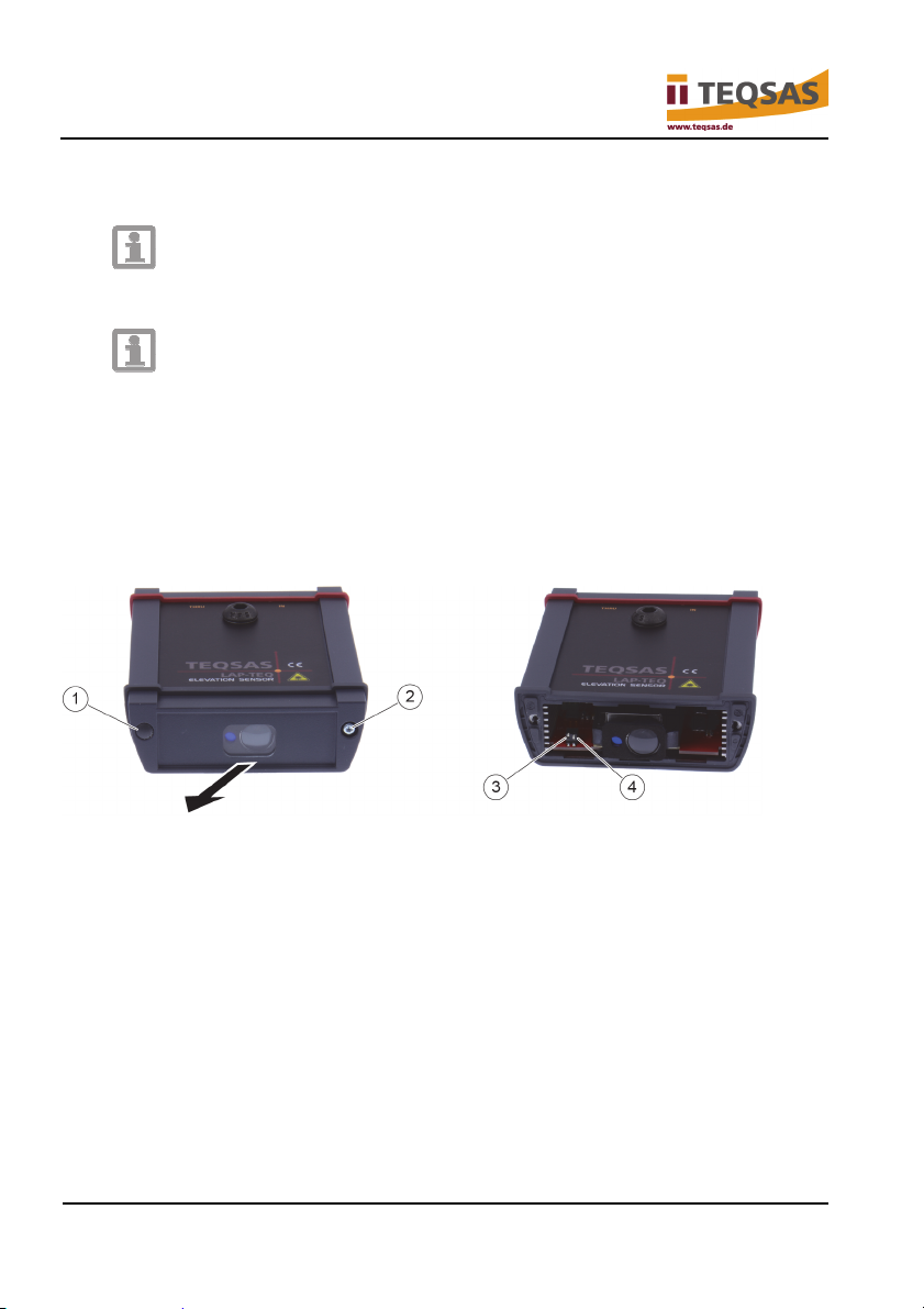
► Remove the two caps (1) on the display unit with a small screwdriver.
► Unscrew both screws (2).
► Remove the cover.
► Set DIP switches (3) and (4).
► Set length unit to metres or feet – DIP switch 1, left (3):
- Metres: Set DIP switch 1 to “ON”.
- Feet: Set DIP switch 1 to “OFF”.
► Activate/deactivate trigonometric correction – DIP switch 2, right (4):
20 V-11/2018
Page 21

Trigonometric correction / length unit
- Activate trigonometric correction: Set DIP switch 2 to “ON”.
- Deactivate trigonometric correction: Set DIP switch 2 to “OFF”.
► Replace cover.
► Screw in the two screws (2).
► Press on both caps (1).
LAP-TEQ Elevation 21
Page 22
Cleaning and care
7 Cleaning and care
Danger!
Risk of fatal injury from electric shock!
► Before working on the device, always disconnect the
XLR cable to the display unit (power supply).
Attention!
Danger of damage to device!
► Do not immerse the device in water for cleaning, since
water could penetrate and damage the electrical
components.
Attention!
Potential damage to product!
► To clean the housing, use a soft, lint-free cleaning cloth moistened with
mild soap suds.
► Avoid scouring movements on the display and the glass pane that closes
the laser beam exit opening.
► Never use chemicals, cleaning agents or solvents. This can cause
discolouration and corrosion on the outside of the device or can result in
electric shock or fire.
The surface can be damaged.
► Never use scratching or abrasive objects or aggressive
cleaners to clean the device.
22 V-11/2018
Page 23
Malfunctions and troubleshooting
8 Malfunctions and troubleshooting
Caution!
Danger of injury!
Malfunctions are often caused by minor errors. Usually you can remedy them
yourself. Please refer to the following table before contacting your dealer. It will
save you a great deal of trouble and possibly also expense.
If the device needs to be serviced, take it to your sales partner.
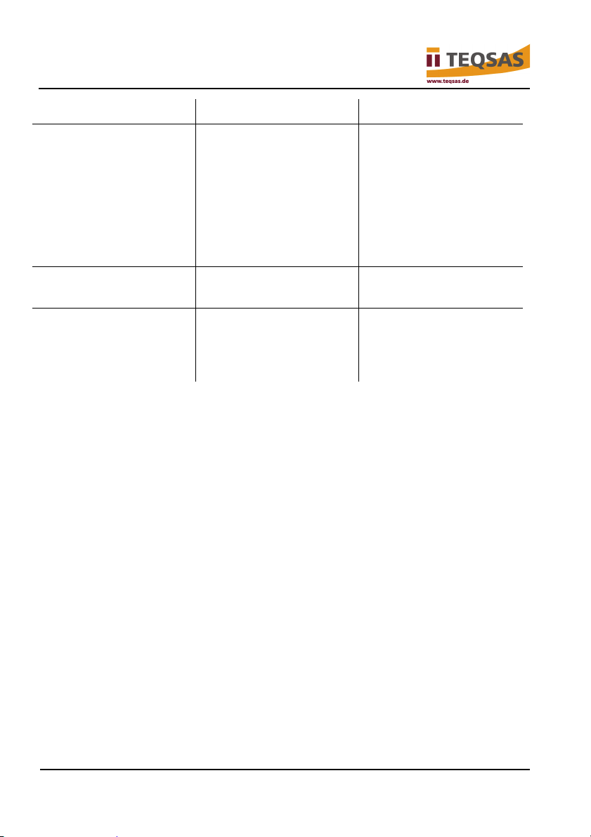
Error/malfunction Cause Remedy
Unauthorised repairs can have the result that your device
no longer functions safely. That endangers yourself and
your environment.
Device does not
function.
Laser not visible. Poor ambient
Device defective? Contact service
department.
Refer to information on
conditions?
ambient conditions in
this manual.
Cable too long? Use an XLR cable with
a larger cross section.
Measuring distance too
large?
LAP-TEQ Elevation 23
If possible, reduce the
measuring distance.
Page 24
Malfunctions and troubleshooting
Error/malfunction Cause Remedy
The display shows
“?.?m” or “?.?ft”
The unit can find no
end point for the
measurement.
Check the
measurement end point
and/or line of sight
between the unit and
the measurement end
point.
Can the elevation unit
stabilise freely?
Three dashes appear
on the display.
Magnetic mounting
bracket is not held or
not sufficiently held by
the magnets.
XLR cable not correctly
plugged in?
Magnets were
damaged by heat or
impact.
Push XLR cable in
firmly.
Replace magnetic
mounting bracket.
If you cannot remedy the error yourself, contact our service department.
Please note that unauthorised repairs will also void the warranty and can result
in additional costs.
8.1 Service centre
TEQSAS GmbH
Otto-Hahn-Straße 20a
50354 Hürth
Germany
Phone: +49 (0)2233 611-500
E-mail: [email protected]
24 V-11/2018
Page 25
8.2 Observe ambient conditions
Malfunctions and troubleshooting
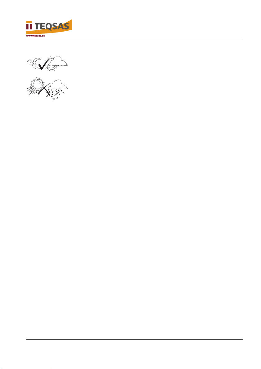
The visibility of the laser beam depends on the ambient brightness.
In general:
Subdued light = good visibility
Direct sunlight = poor visibility
Rain, dust or vapour = poor visibility
Other interfering influences:
Measurements through glass or plastic panes
Dirty laser beam exit opening
High temperature deviations: Before using in a very hot or cold
environment, allow the device to adjust to the ambient temperature while
in the transport case.
LAP-TEQ Elevation 25
Page 26
Storage
9 Storage
► Clean and dry all parts and store them in a clean and dry place.
► If you are not going to use or transport the device for an extended period,
store it in the original package.
Attention!
Danger of damage to device!
High temperatures can damage the device or permanently
weaken the magnetic force of the magnets.
► Do not store the device in very hot locations such as
the inside of a car in summer or at locations with
exposure to direct sunlight.
26 V-11/2018
Page 27

10 Disposal
The packaging consists of environmentally friendly materials that
can be disposed of at your local recycling centre.
Devices that are marked with the symbol opposite are not to be
disposed of with the household trash. You under obligation to
dispose of such electrical and electronic devices separately.
Disposal
Contact your local or municipal authority to find out more about
where to dispose of used appliances.
Separate disposal old appliances allows recycling or reuse of the
materials. This prevents pollution of the environment from
undesirable substances.
LAP-TEQ Elevation 27
Page 28

Technical data
11 Technical data
LAP-TEQ Elevation Sensor
Protection type IP40
Optic Spot optic
Laser class 2 (<1 mW)
Laser colour 635 nm (red)
Measuring range
0.05 m to 40 m (in
optimal conditions)
Measuring tolerance range +/-1 mm (in optimal
conditions), otherwise up
to +/-3 mm)
Permissible ambient temperature for operation 0 – 40 °C
Permissible ambient temperature for storage -20 – 50 °C
Dimensions 130 × 99 × 108 mm
(without magnetic
mounting bracket, with
mechanical quickrelease connector)
Weight 650 g
Total weight of set 905 g
Order number 1670
The manufacturer reserves the right to make technical modifications to the
product or product group without prior notice.
28 V-11/2018
Page 29
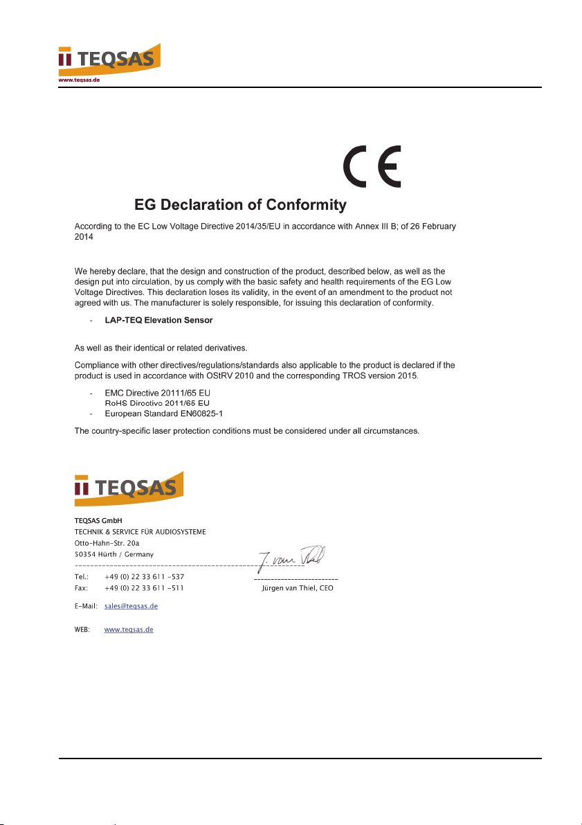
12 Declaration of Conformity
Declaration of Conformity
LAP-TEQ Elevation 29
Page 30

TEQSAS GmbH
Otto-Hahn-Str. 20a
50354 Hürth
Germany
Phone: +49 (0)2233 611-500
Fax: +49 (0)2233 611-511
E-mail: [email protected]
Web: www.teqsas.de
 Loading...