

Page 1
UUCC PPrroo SSeerrvveerr
Teo Technologies, Inc.
11609 49th Place West
Mukilteo, WA 98275-4255
(800) 524-0024 (425) 349-1000
Fax (425) 349-1010
www.teotech.com
IInnssttaallllaattiioonn IInnssttrruuccttiioonnss
13-280137 Rev. C
June 2013
Page 2

Teo UC Pro Server Installation Instructions
© 2013 Teo Technologies, Inc.. All rights reserved.
Page 2 13-280137 Rev. C
Page 3

C
o
n
t
e
n
t
s
C
o
n
t
e
C
o
n
Introduction ................................................................................................................................. 5
Using this Manual ................................................................................................................. 5
Front Panel ............................................................................................................................ 6
Back Panel ............................................................................................................................. 8
Installation ................................................................................................................................... 9
Installation Overview ............................................................................................................ 9
Safety Guidelines and General Installation ....................................................................... 10
Rack Mounting .................................................................................................................... 12
Power .................................................................................................................................. 17
Ethernet Network Connection ............................................................................................ 18
Telephony Connections...................................................................................................... 19
Configuration and Administration ........................................................................................... 27
Joining the Local Domain .................................................................................................. 27
Configuring System Options ............................................................................................. 27
User Configuration Options ............................................................................................... 29
n
t
e
n
t
s
t
s
Specifications ............................................................................................................................ 31
Service and Warranty ................................................................................................................ 33
Service ................................................................................................................................. 33
Teo Product Warranty ........................................................................................................ 33
Safety and Regulatory Requirements ...................................................................................... 35
Cautions .............................................................................................................................. 35
FCC Part 15 .......................................................................................................................... 35
National Electrical Code ..................................................................................................... 35
13-280137 Rev. C Page 3
Page 4

Teo UC Pro Server Installation Instructions
Page 4 13-280137 Rev. C
Page 5

I
n
t
r
o
d
u
c
t
i
o
n
I
n
t
r
o
d
u
c
t
I
n
t
r
o
d
u
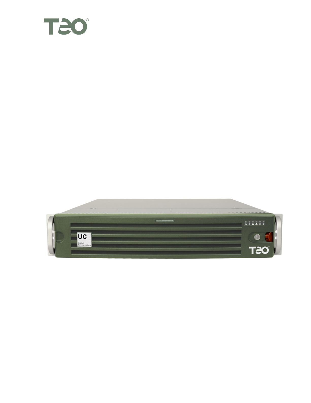
The Teo UC (Unified Communications) System is a SIP-based VoIP platform that integrates
a wide variety of communications services via a software-based solution that runs on the
UC Pro Server or the smaller-capacity UC Mini Server. The servers run proprietary Teo
software on a Linux operating system, and can be configured for a wide range of station
and call capacities.
Features of the UC system include:
• Automated Attendant
• Voicemail
• Conferencing
• Call reporting
• Call recording
• Mobile phone support
• Softphone
• Presence-based call routing
• Fax Server
• E911
• LDAP/Active Directory integration
• Mass provisioning of users
• Mass provisioning of devices
• Centralized administration of all system functions
c
i
t
o
n
o
n
i
UUssiinngg tthhiiss MMaannuuaall
This manual covers the hardware installation and initial configuration of the UC Pro Server.
• Connectors, switches, and indicators on the front and back panels are described in
this chapter.
• The Installation chapter covers rack mounting, line and device connection, and
power.
• The Configuration and Administration chapter gives a brief introduction to the web-
based Administration and User Portals. Detailed online help for these tools can be
accessed from the portal interfaces.
13-280137 Rev. C Page 5
Page 6
Teo UC Pro Server Installation Instructions
FFrroonntt PPaanneell
Seven computer and network status indicators are located on the UC Pro Server front
panel.
Remove the front bezel to access the reset button, power button, hard drive bays, USB and
serial ports, and a DVD drive.
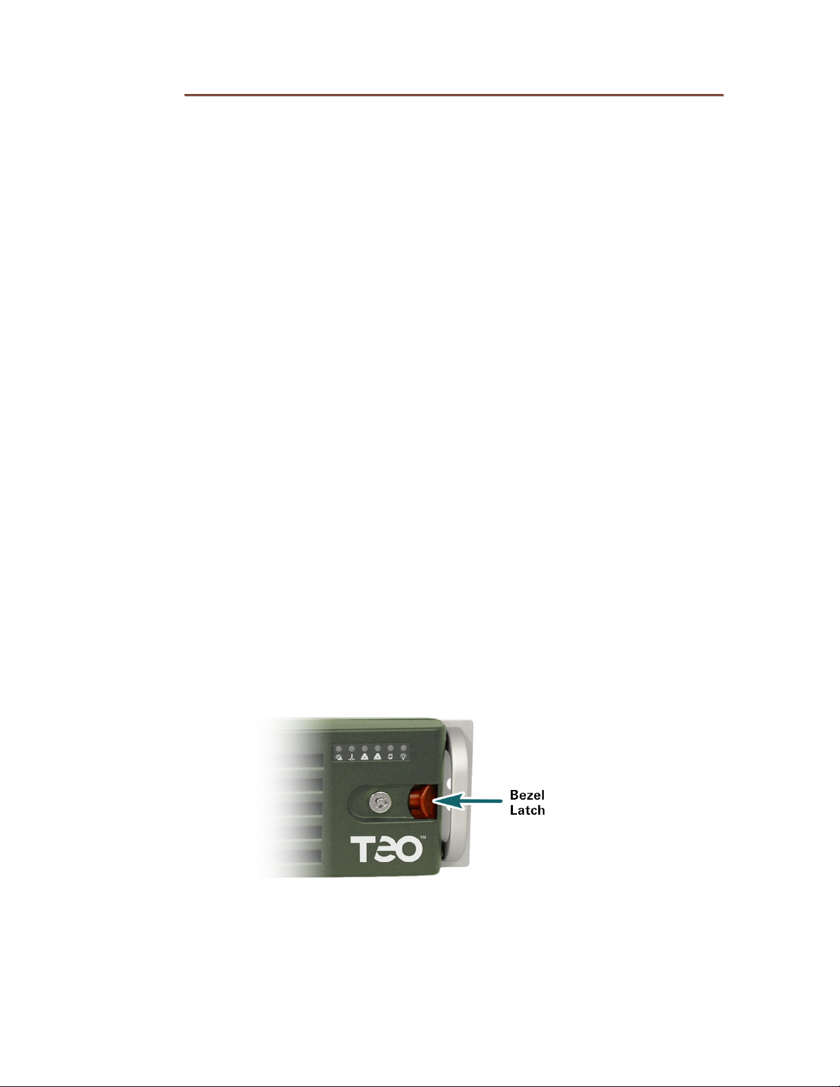
FFrroonntt BBeezzeell RReemmoovvaall
Press the red lever left to unlatch the front bezel, and then pull the bezel forward to
remove. The bezel may be locked (using the included key) to prevent removal.
Page 6 13-280137 Rev. C
Page 7
Introduction
CCoommppuutteerr//NNeettwwoorrkk CCoonnttrrooll PPaanneell
The UC Pro Server has a switch and indicator area on the front panel. Indicators can be
viewed with the front bezel in place; remove the bezel to access the reset and power
buttons.
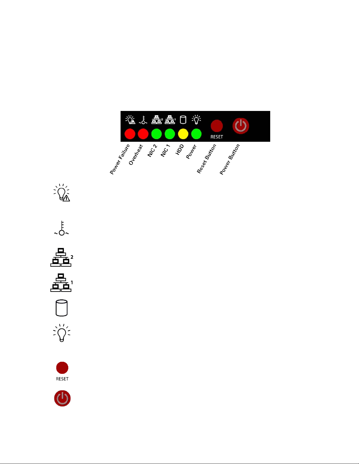
IInnddiiccaattoorrss aanndd SSwwiittcchheess
The indicators on this panel show the status of the internal computer system and network
connections. The power switch and reset button are also located here.
Power Failure – flashing indicates a failure in either of the two redundant hotswappable power supplies.
Overheat/Fan Fail – flashing indicates a fan failure. Continuously on (not
flashing) indicates an overheat condition, which may be caused by cables
obstructing the airflow in the system or the ambient room temperature being too
warm.
NIC 2 – flashing indicates network activity on Ethernet interface 2 (WAN).
NIC 1 – flashing indicates network activity on Ethernet interface 1 (LAN).
HDD – flashing indicates hard drive and/or DVD-ROM drive activity.
Power – indicates that power is being supplied to the system's power supply
units. This indicator should normally be illuminated when the system is
operating.
Reset Button – press to force a reboot of the system.
Power Button – used to apply or remove power from the power supplies to the
server system.Turning off system power with this button removes the main
power but keeps standby power supplied to the system.Therefore, you must
unplug both system power cords before servicing.
13-280137 Rev. C Page 7
Page 8

Teo UC Pro Server Installation Instructions
BBaacckk PPaanneell
The back panel has connectors for:
• Power supplies
• Ethernet ports
• PRI ports
• Analog ports
• Other computer connectors (typically used for troubleshooting only)
o Keyboard
o Mouse
o VGA video
o RS232 serial port
o USB ports
Page 8 13-280137 Rev. C
Page 9

I
n
s
t
a
l
l
a
t
i
o
n
I
n
s
t
a
l
l
a
t
I
n
s
t
a
l
IInnssttaallllaattiioonn OOvveerrvviieeww
The UC Pro Server is shipped with all ordered options installed at the factory.
You will need to perform the following steps to install the UC Pro Server:
1. Mount the UC Pro Server in the rack.
2. Connect the UC Pro Server to the LAN.
3. Connect the Telco ISDN-PRI port(s) to the UC Pro Server.
4. Connect AC power.
5. Connect optional analog lines and analog devices to the UC Pro Server.
6. Configure the UC Pro Server to join the network domain.
i
l
a
t
o
n
o
n
i
13-280137 Rev. C Page 9
Page 10
Teo UC Pro Server Installation Instructions
SSaaffeettyy GGuuiiddeelliinneess aanndd GGeenneerraall IInnssttaallllaattiioonn
SSaaffeettyy GGuuiiddeelliinneess
Prior to installing the system, read and follow all safety guidelines. The UC Pro Server must
be installed only by qualified personnel. The following warnings and cautions must be
observed during installation and operation of the system.
Never install telephone wiring during a lightning storm.
Never install telephone jacks in wet locations unless the jack is
specifically designed for wet locations.
Never touch uninsulated telephone wires or terminals unless the
telephone line has been disconnected at the network interface.
Do not attach or staple the AC power cord to any building surface.
WARNING!
RISK OF ELECTRICAL SHOCK!
CAUTION!
To reduce the risk of fire, use only No. 26 AWG UL Listed or CSA
Certified Telecommunications Line Cord for all connections to the
telephone network.
CAUTION!
This equipment shall be installed only in restricted access areas in
accordance with Articles 110-16, 110-17 and 110-18 of the National
Electrical Code ANSI/NFPA No. 70–1987 and any local codes as
required.
Page 10 13-280137 Rev. C
Page 11

Installation
UUnnppaacckk aanndd IInnssppeecctt tthhee EEqquuiippmmeenntt
Check the components for damage that might have occurred during shipment. If any
equipment is damaged, contact the carrier. Verify that the shipment is complete by
comparing the shipped equipment with the shipping list.
The following items are included:
(1) UC Pro Server
(2) Power cords
(2) Brackets for 19" rack mounting
(4) Mounting bracket thumbscrews
(2) Rack inner rails
(2) Rack inner rail extensions
(6) Rack inner rail screws
(2) Rack long (front) outer rails
(2) Rack short (rear) outer rails
(1) Front bezel key
(1) Installation Instructions (this manual)
LLooccaattiioonn RReeqquuiirreemmeennttss
The UC Pro Server installation requires a clean, secure room on the customer premises.
The room must have adequate ventilation and room for front and rear panel access. The
UC Pro Server must be installed per articles 115-15, 110-17 and 110-18 of the National
Electrical Code ANSI/MFPA.
The UC Pro Server must be mounted in a 19" equipment rack.
EEnnvviirroonnmmeennttaall CCoonnssiiddeerraattiioonnss
The UC Pro Server is designed to operate within the following environmental limits:
Operating Temperature: 0° to 40° C (outside the chassis)
Operating Humidity: Up to 95% (non-condensing)
13-280137 Rev. C Page 11
Page 12

Teo UC Pro Server Installation Instructions
RRaacckk MMoouunnttiinngg
RRaacckk PPrreeccaauuttiioonnss
• Ensure that the leveling jacks on the bottom of the rack are fully extended to the
floor with the full weight of the rack resting on them.
• In a single rack installation, stabilizers should be attached to the rack.
• In multiple rack installations, the racks should be coupled together.
• Always make sure the rack is stable before extending a component from the rack.
• You should extend only one component at a time – extending two or more
simultaneously may cause the rack to become unstable.
• Determine the placement of each component in the rack before you install the rails.
• Install the heaviest server components on the bottom of the rack first, and then work
up.
• Always keep the rack's front door and all panels and components on the servers
closed when not servicing to maintain proper cooling.
• Equipment should be mounted into a rack so that the amount of airflow required for
safe operation is not compromised.
• Equipment should be mounted into a rack so that a hazardous condition does not
arise due to uneven mechanical loading.
• A reliable ground must be maintained at all times. To ensure this, the rack itself
should be grounded. Particular attention should be given to power supply
connections other than the direct connections to the branch circuit (i.e. the use of
power strips, etc.).
• The UC Pro Server weighs approximately 40 lbs. Make sure that the rack unit is
capable of properly supporting this weight.
Page 12 13-280137 Rev. C
Page 13

Installation
MMoouunnttiinngg IInnssttrruuccttiioonnss
There are a variety of rack units on the market, which may mean that the assembly
procedure will differ slightly. You should also refer to the installation instructions that
came with the rack unit you are using.
IIddeennttiiffyyiinngg tthhee SSeeccttiioonnss ooff tthhee RRaacckk RRaaiillss
Two rack rail assemblies are included in the rack mounting kit. Each assembly consists of
two sections: an inner fixed chassis rail that secures directly to the server chassis, and an
outer fixed rack rail that secures directly to the rack itself.
SSeeppaarraattiinngg tthhee IInnnneerr aanndd OOuutteerr RRaaiillss
1. Locate the rail assembly in the chassis packaging.
2. Extend the rail assembly by pulling it outward.
3. Press the quick-release tab.
4. Separate the inner rail extension from the outer rail assembly.
13-280137 Rev. C Page 13
Page 14

Teo UC Pro Server Installation Instructions
IInnssttaalllliinngg tthhee IInnnneerr RRaaiill EExxtteennssiioonnss
The UC Pro Server includes a set of inner rails in two sections: inner rails and inner rail
extensions. The inner rails are pre-attached. The inner rail extension is attached to the
inner rail to mount the chassis in the rack.
1. Place the inner rack extensions on the side of the chassis, aligning the hooks of the
chassis with the rail extension holes. Make sure that the extension faces "outward"
just like the pre-attached inner rail.
2. Slide the extension toward the front of the chassis.
3. Secure the chassis with 2 screws as illustrated. Repeat steps for the other inner rail
extension.
Page 14 13-280137 Rev. C
Page 15

Installation
IInnssttaalllliinngg tthhee OOuutteerr RRaaiillss ttoo tthhee RRaacckk
Outer rails attach to the server rack and hold the server in place. The outer rails extend
between 30 inches and 33 inches.
1. Secure the back end of the outer rail to the rack, using the screws provided.
2. Press the button where the two outer rails are joined to retract the smaller outer rail.
3. Hang the hooks of the rails onto the rack holes and if desired, use screws to 3.
secure the front of the outer rail onto the rack.
4. Repeat steps 1-3 for the remaining outer rail.
13-280137 Rev. C Page 15
Page 16

Teo UC Pro Server Installation Instructions
IInnssttaalllliinngg tthhee CChhaassssiiss iinnttoo aa RRaacckk
1. Extend the outer rails as illustrated below.
2. Align the inner rails of the chassis with the outer rails on the rack.
3. Slide the inner rails into the outer rails, keeping the pressure even on both sides.
When the chassis has been pushed completely into the rack, it should click into the
locked position.
4. Optional screws may be used to secure the front of the server to the rack.
Page 16 13-280137 Rev. C
Page 17

Installation
PPoowweerr
The UC Pro Server is equipped with two redundant hot-swappable power supplies.
Connect the power connectors on the back panel to standard 120 VAC, 60 Hz power outlets
using the supplied IEC power cords.
If multiple circuits are available at the equipment site, connect each power cord to a
separate power circuit to ensure that the server will continue to operate if one circuit fails.
Your system is configured in the computer BIOS to automatically start when power is
connected. This setting ensures that the UC Pro Server will restart in the event of a
temporary loss of power.
To manually turn the UC Pro Server off or on, press the power button (page 7).
13-280137 Rev. C Page 17
Page 18

Teo UC Pro Server Installation Instructions
EEtthheerrnneett NNeettwwoorrkk CCoonnnneeccttiioonn
Use a Category 5 or better network cable.
• Connect the ETH0 port on the UC Pro Server to your LAN. The local SIP telephone
devices are on this LAN.
• DO NOT connect anything to the ETH1 port.
Page 18 13-280137 Rev. C
Page 19

Installation
TTeelleepphhoonnyy CCoonnnneeccttiioonnss
The UC Pro Server may be configured at the factory with one or more optional telephony
port cards, which can include PRI trunk, analog trunk (FXO), and analog device (FXS) ports.
Use the images below to identify the ports on your UC Pro Server.
PPoorrtt IIddeennttiiffiiccaattiioonn
Note – The connector orientation may be reversed (rotated 180°) on some cards.
PPRRII TTrruunnkk PPoorrtt
AAnnaalloogg PPoorrttss
Eight-position connector surrounded by a metal shield –
connects to an ISDN Primary Rate Interface (PRI) trunk.
To determine analog port configuration, apply power to the server before connecting any
analog trunks or station devices, this will illuminate the installed ports. The color and size
of the connector indicates the port configuration.
Analog Station Device (FXS) Port
Four- or six-position connector, lit green – connects to one
analog station device, such as a telephone or fax machine.
Analog Trunk (FXO) Port, 1 trunk
Four-position connector, lit red – connects to one analog loop
start trunk.
Analog Trunk (FXO) Port, 2 trunks
Six-position connector, lit red – connects to two analog loop
start trunks.
13-280137 Rev. C Page 19
Page 20

Teo UC Pro Server Installation Instructions
OOnnee,, TTwwoo,,
oorr FFoouurr
PPRRII PPoorrttss
CCaarrdd CCoonnffiigguurraattiioonnss
Available factory-installed telephony cards are shown in this section. Up to eight cards in
any combination can be installed in the UC Pro Server.
FFoouurr FFXXSS//FFXXOO PPoorrttss
This card can be
configured with
(4) FXS, (4) FXO, or
(2) FXS + (2) FXO ports.
OOnnee FFXXSS ++
FFoouurr FFXXOO PPoorrttss
Each FXO connector
on this card has two
ports.
Line splitter cords
are supplied with
this card option.
Page 20 13-280137 Rev. C
OOnnee PPRRII ++
OOnnee FFXXSS ++
FFoouurr FFXXOO PPoorrttss
This card is similar
to the one shown
at the left, with the
addition of (1) PRI
port.
Page 21

Installation
CCoonnnneeccttiinngg ttoo TTeellccoo PPRRII TTrruunnkkss
Connection to the external telephone network is typically through one or more ISDN PRI
trunks. Each PRI port can be configured to support up to 23 simultaneous calls.
Multiple cards with PRI ports may be installed; some cards may also include analog ports.
When facing the back of the server, card 1 is on the left, as shown below. Ports on each
card are numbered 1-4, with port 1 on the bottom.
Note – The connector arrangement and number of connectors per card may differ, depending on
the server configuration.
• Connect each PRI port to an ISDN PRI trunk, using standard Ethernet cables.
Note – Some installations may require a PRI swap cable or swap adapter to reverse the
transmit and receive pairs.
IISSDDNN PPRRII TTrruunnkk PPoorrtt CCoonnnneeccttoorr PPiinnoouutt ((wwiitthh CCrroossssoovveerr CCaabbllee))
Pin Number PRI Port Trunk
1 Transmit Tip Receive Tip
2 Transmit Ring Receive Ring
3 – –
4 Receive Tip Transmit Tip
5 Receive Ring Transmit Ring
6 – –
7 – –
8 – –
13-280137 Rev. C Page 21
Page 22

Teo UC Pro Server Installation Instructions
AAnnaalloogg CCoonnnneeccttiioonnss
WARNING! RISK OF EQUIPMENT DAMAGE!
The UC Pro Server supplies power on FXS device ports, and receives
power from the telephone trunks on FXO trunk ports.
Ensure that the correct UC Pro Server ports are used when connecting
analog trunks or station devices.
Multiple cards with analog ports may be installed; some cards may also include PRI ports.
When facing the back of the server, card 1 is on the left, as shown below. Ports on each
card are numbered 1-4, with port 1 on the bottom.
Note – The connector arrangement and number of connectors per card may differ, depending on
the server configuration.
• To determine analog port configuration, apply power to the UC Pro Server to
illuminate the ports (page 19).
Page 22 13-280137 Rev. C
Page 23

Installation
CCoonnnneeccttiinngg ttoo AAnnaalloogg TTrruunnkks
FXO ports connect to standard analog loop start (POTS) telephone trunks.
Your UC Pro Server may have 4-position connectors supporting one trunk, and/or 6position connectors supporting two trunks; follow the appropriate instructions below.
Note – The connector orientation may be reversed (rotated 180°) on some cards.
s
44--PPoossiittiioonn CCoonnnneeccttoorr
• Use the supplied yellow crossover cord. Connect the 4-position plug to the server,
and connect the 6-position plug to the analog trunk jack.
66--PPoossiittiioonn CCoonnnneeccttoorr
• Use the supplied line splitter cord as shown to connect to two individual 6-position
trunk jacks.
The lower numbered trunk port is labeled "Port N" on the cord, and the higher
numbered port is labeled "Port N+1".
13-280137 Rev. C Page 23
Page 24

Teo UC Pro Server Installation Instructions
AAnnaalloogg TTrruunnkk ((FFXXOO)) PPoorrtt CCoonnnneeccttoorr PPiinnoouuttss
Server Pin
Number
(4-Position Plug)
– – –
1 5 –
2 4 Tip
3 3 Ring
4 2 –
– – –
Server Pin
Number
(6-Position Plug)
Analog Trunk 1
Pin Number
(6-Position Plug)
Analog Trunk
Pin Number
(6-Position Plug)
Signal
Analog Trunk 2
Pin Number
(6-Position Plug)
Signal
1 –
2 4 Tip 2
3 4 Tip 1
4 3 Ring 1
5 3 Ring 2
6 –
Page 24 13-280137 Rev. C
Page 25

Installation
CCoonnnneeccttiinngg ttoo AAnnaalloogg SSttaattiioonn DDeevviicceess
FXS ports connect to analog (POTS) station devices, such as telephones or fax machines.
Your UC Pro Server may have 4-position or 6-position connectors; follow the appropriate
instructions below.
Note – The connector orientation may be reversed (rotated 180°) on some cards.
44--PPoossiittiioonn CCoonnnneeccttoorr
• Use the supplied yellow crossover cord. Connect the 4-position plug to the server,
and connect the 6-position plug to the analog device.
66--PPoossiittiioonn CCoonnnneeccttoorr
• Use a standard telephone line cord to connect to the analog device.
AAnnaalloogg DDeevviiccee ((FFXXSS)) PPoorrtt CCoonnnneeccttoorr PPiinnoouutt
Server Pin
Number
(4-Position Plug)
– 1 6 –
1 2 5 –
2 3 4 Tip
3 4 3 Ring
4 5 2 –
– 6 1 –
Server Pin
Number
(6-Position Plug)
Analog Device
Pin Number
(6-Position Plug)
Signal
13-280137 Rev. C Page 25
Page 26

Teo UC Pro Server Installation Instructions
Page 26 13-280137 Rev. C
Page 27

C
o
n
f
i
g
u
r
a
t
i
o
n
a
n
d
A
d
m
i
n
i
s
t
r
a
t
i
o
n
C
o
n
f
i
g
u
r
a
t
i
o
n
a
n
d
A
d
m
i
n
i
s
t
r
a
t
C
o
n
f
i
g
u
r
a
t
i
o
n
a
n
d
A
d
m
i
n
i
s
t
JJooiinniinngg tthhee LLooccaall DDoommaaiinn
The UC Pro Server may be preconfigured at the factory with a network address specified
by the customer. If no custom address was requested, the system will be configured with
DHCP enabled.
Network addresses can be changed from the System Configuration – Network Resources
options in the Administration portal.
CCoonnffiigguurriinngg SSyysstteemm OOppttiioonnss
1. All configurable options are set via a web-based remote administration session.
2. Open a web browser on any computer that has access to the LAN. A widescreen
display of at least 1680 x 1050 resolution is recommended. Adobe Flash Player is
required.
i
r
a
t
o
n
o
n
i
3. Browse to the address of the UC Pro Server.
4. When the login screen appears, log in to the UC Pro Server using the administration
username and password that was supplied by Teo (you can change the username
and password or add additional administration accounts later).
• The Administration Dashboard will be shown.
13-280137 Rev. C Page 27
Page 28

Teo UC Pro Server Installation Instructions
Use the menus at the top of the screen to access the configuration options.
Online help is available for most configuration options. Click the
icon to view help in a
new browser tab or window.
When finished with the administration session, click LOGOUT at the upper right of
the screen.
Page 28 13-280137 Rev. C
Page 29

Troubleshooting
UUsseerr CCoonnffiigguurraattiioonn OOppttiioonnss
Each telephone user can configure a limited set of options. The administrator must set up
an account name and password for each user.
• The user needs to browse to the login page (UC Pro Server address). A display
resolution of 1024 x 768 is sufficient for the User Portal interface. Adobe Flash Player
is required.
After logging in, the user can access their call history and configuration options.
Online help is available for most configuration options by clicking the
13-280137 Rev. C Page 29
icon.
Page 30

Teo UC Pro Server Installation Instructions
Page 30 13-280137 Rev. C
Page 31

S
p
e
c
i
f
i
c
a
t
i
o
n
s
S
S
p
p
e
e
c
c
i
f
i
c
a
t
i
a
o
t
i
o
i
f
i
c
n
n
s
s
PPoowweerr RReeqquuiirreemmeennttss
Voltage .................................. 100–240 VAC
Current................................... 10 A (@100 V) / 4 A (@240V) max. per outlet (2 required)
PPhhyyssiiccaall
Dimensions ........................... 3.5" H x 19" W x 27" D (including mounting brackets)
Weight ................................... 40 lbs.
EEnnvviirroonnmmeennttaall
Operating Temperature ........ 32° to 104° F (0° to 40° C)
Storage Temperature ........... -4° to 185° F (-20° to 85° C)
Humidity ................................ 0 to 95%, non-condensing
13-280137 Rev. C Page 31
Page 32

Teo UC Pro Server Installation Instructions
Page 32 13-280137 Rev. C
Page 33

S
e
r
v
i
c
e
a
n
d
W
a
r
r
a
n
t
y
S
e
r
v
i
c
e
a
n
d
W
a
r
r
a
S
e
r
v
i
c
e
a
n
d
W
a
SSeerrvviiccee
The Teo UC Pro Server has no user-serviceable parts inside; repair must be done by Teo.
Prior to equipment removal, call Teo Customer Technical Support for assistance in
determining the source of the problem. This critical action can often prevent needless
removal of equipment and subsequent customer inconvenience.
n
r
r
a
n
t
y
t
y
Teo
Technical Support Department
11609 49
Mukilteo, WA 98275-4255 USA
Teo is committed to meeting the product needs of our customers. Please write or call us
with any suggestions for improvement.
TTeeoo PPrroodduucctt WWaarrrraannttyy
For a period of one year from date of dealer purchase, but not to exceed 16 months from
date of manufacture, Teo Technologies, Inc. (Teo) warrants its products to be free from
defects in material and workmanship under conditions of normal use and service. Teo
shall, at its option, repair or replace any defective product which, in its opinion, has not
been misused, damaged, or improperly installed.
Repair or replacement under this warranty will be performed at Teo's factory.
Authorization must be obtained from Teo prior to returning a product for repair. Freight
must be prepaid for all units returned to Teo. Units repaired under warranty will be
shipped UPS Ground (or equivalent), freight prepaid by Teo.
th
Place West
Phone: (425) 349-1000
(800) 524-0024
Fax: (425) 349-1010
E-mail: tech@teotech.com
: www.teotech.com
Web
Products that are older than the warranty period, but less than 7 years old, or still
manufactured by Teo may be repaired at the factory for a flat rate charge. Repaired out-ofwarranty units are warranted for 90 days from the date of repair.
The repair or replacement of a product under this warranty represents the entire obligation
of Teo; Teo shall not be liable for any special or consequential damages resulting from or
caused by any defect, failure, incapacity or malfunction of any of its products.
The foregoing express warranty is in lieu of all other warranties, express or implied,
including but not limited to any implied warranty of merchantability, fitness, or
adequacy for any purpose or use, quality, productiveness or capacity; Teo, to the
extent permitted by law, hereby disclaims all such other warranties.
13-280137 Rev. C Page 33
Page 34

Teo UC Pro Server Installation Instructions
Page 34 13-280137 Rev. C
Page 35

S
a
f
e
t
y
a
n
d
R
e
g
u
l
a
t
o
r
y
R
e
q
u
i
r
e
m
e
n
t
s
S
S
a
a
f
e
t
y
a
n
d
R
e
g
u
l
a
t
o
r
y
R
e
q
u
i
r
e
m
e
f
e
t
y
a
n
d
R
e
g
u
l
a
t
o
r
y
R
e
q
u
i
r
e
m
e
n
n
t
s
t
s
CCaauuttiioonnss
• Power wiring must be 18 AWG or larger.
• Do NOT attach or staple any Power Wiring to any building surface.
• Risk of electrical shock! Disconnect power before opening unit.
• At no time during connecting or routing of cables should power be applied to the
• Use caution when installing or modifying telephone wiring.
• Never touch uninsulated telephone wiring unless it is disconnected at the network
• Never install telephone jacks in wet locations unless jack is designed for wet
• Do not use solvents or liquids to remove dust or dirt from the UC Pro Server.
FFCCCC PPaarrtt 1155
equipment.
interface.
locations.
This equipment has been tested and found to comply with the limits for a Class A digital
device, pursuant to the Part 15 of the FCC rules. These limits are designed to provide
reasonable protection against harmful interference when the equipment is operated in a
commercial environment. This unit generates, uses, and can radiate radio frequency
energy and, if not installed and used in accordance with the instruction manual, may cause
harmful interference to radio communications. Operation of this equipment in a residential
area is likely to cause harmful interference in which case the user will be required to
correct the interference at his own expense. Changes or modifications not expressly
approved by the party responsible for compliance could void the user’s authority to
operate the equipment.
NNaattiioonnaall EElleeccttrriiccaall CCooddee
This equipment shall be installed only in restricted access areas in accordance with Article
800 of the National Electrical Code ANSI/NFPA No. 70 1999 and any local codes as
required. All external wiring should follow current National Electrical Code requirements.
13-280137 Rev. C Page 35
Page 36

Teo UC Pro Server Installation Instructions
Page 36 13-280137 Rev. C
 Loading...