

Page 1
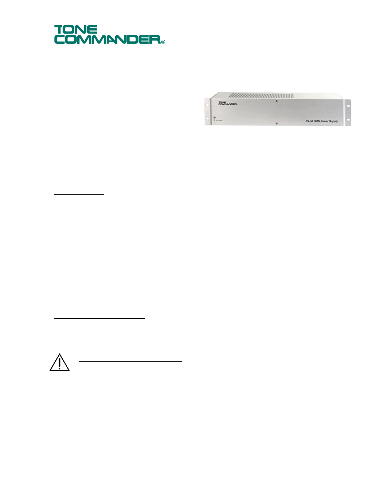
PS-50 ISDN Power Suppl
y
Installation
Instructions
The PS-50 is a rack- or wall-mountable bulk
power supply for powering ISDN telephones
and NT1 Network Terminations.
Fifty -48 VDC output connections are
provided. Each output has self-resetting
current limiting protection at 250 mA. The total
available output current is 2.8 A, which is
suitable to power up to 50 Tone Commander
ISDN telephones.
Optional NT1-200 Battery Backup Power Supply and NT1-200 Add-on Battery units can be added to the
PS-50 to enable uninterrupted ISDN power during a power failure.
Specifications
Power Requirements ................ 120 VAC, 60 Hz, single phase, 2 A maximum
Output Voltage .......................... -48 VDC nominal, -56 VDC maximum
Output Current .......................... current limited at 250 mA per output pair, 2.8 A total (50 pairs)
Output Power, Total................... 150 watts
Output Connectors .................... (2) 50-position ribbon cable connectors (Amphenol type)
Short Circuit Protection ............. individual self-resetting current limiting for each output
Available Power for Terminals .. 10 watts maximum per output circuit
2.5 watts average per output circuit with 50 loads
150 watts total maximum
Physical Dimensions ................. 3.5” H x 17.25” W x 4.6” D
Weight ....................................... 4.3 lbs.
Operating Temperature ............. 32° - 122° F (0° - 50° C)
Humidity .................................... 5% to 95%, non-condensing
Contents of Shipping Box
(1) PS-50 Power Supply (4) 10-24 x ¼” mounting bracket screws
(2) Mounting brackets (1) Installation Instructions (this document)
Important Safety Instructions
• This equipment is intended for installation in a restricted access location (dedicated equipment
rooms, equipment closets, or the like) in accordance with Articles 110-16, 110-17, and 110-18
of the National Electrical Code, ANSI/NFPA No. 70.
• Never install telephone wiring during a lightning storm.
• Never install telephone jacks in wet locations unless the jack is specifically designed for wet
locations
• Never touch uninsulated telephone wires or terminals unless the telephone line has been
disconnected at the network interface.
• Use caution when installing or modifying telephone wires.
• Do not mount the PS-50 within 12” of a heat source.
• Do not obstruct the heat vents on the top of the unit.
13-280105 Rev. A
March 2005
Page 2
Tone Commander PS-50 ISDN Power Supply Installation Instructions
• Do not obstruct the fan on the rear panel of the unit.
• The socket-outlet shall be installed near the equipment and shall be easily accessible.
Mounting
The PS-50 can be mounted in an EIA standard 19” commercial or 23” telco rack, or wall mounted.
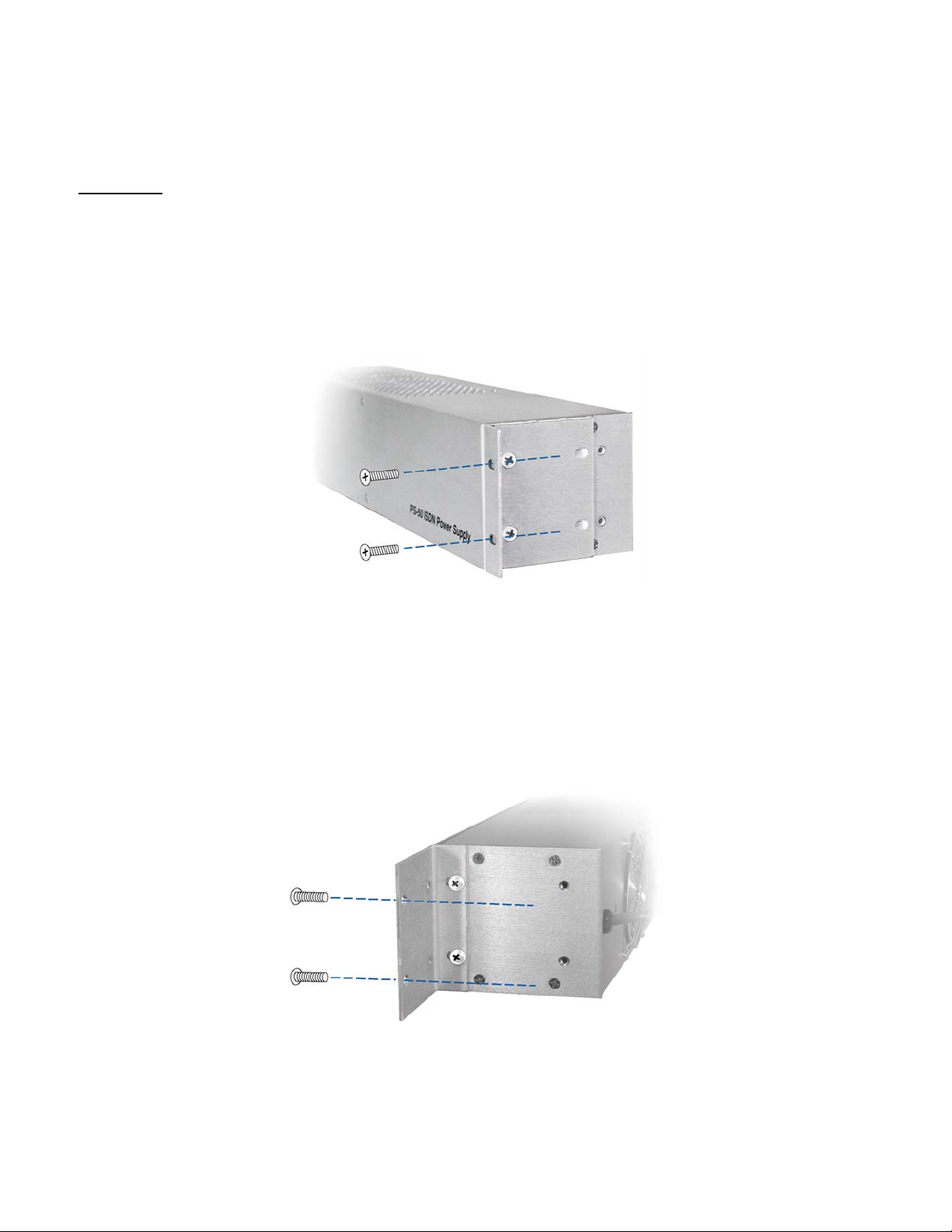
19” Rack Mounting
1. Attach the long sides of the mounting brackets to the PS-50 as shown in Figure 1, using the supplied
mounting bracket screws.
2. Mount the PS-50 to the rack standards using suitable fasteners.
Figure 1 – 19” Rack Mounting
23” Rack Mounting
1. Attach the short side of the mounting brackets to the PS-50 as shown in Figure 2, using the supplied
mounting bracket screws.
2. Mount the PS-50 to the rack standards using suitable fasteners.
Figure 2 – 23” Rack Mounting
Page 2 13-280105 Rev. A
Page 3

Wall Mounting
1. Attach the long side of the mounting brackets to the rear mounting holes on the PS-50 as shown in
Figure 3, using the supplied mounting bracket screws.
2. Mount the PS-50 to the wall using suitable fasteners. Do not obstruct the fan on the rear panel of
the unit.
3. To attach cables, remove the top mounting bracket screw from each side as shown, then tilt the PS-50
forward.
Figure 3 – Wall Mounting
Output Connections
Output connections are supplied on two 50-pin ribbon connectors.
1. Fill out the Number of Units column in Table 2 (on the back page) with the number of telephones, addon devices, NT1s, and/or Battery Backup units that will be powered from the PS-50. Multiply the
number of units by the wattage shown for each device, and enter the result in the Total Power column.
Add all of the entries in the Total Power column to determine the output power required form the PS-
50.
Total power for all devices must not exceed 150 watts.
2. Connect a male-ended ribbon cable from each 50-pin connector on the rear pa nel to a 50-pin
punchdown block. See Table 1 for connector pinout.
3. Cross-connect power pairs from the power punchdown block to the blocks for the devices to be
powered.
Observe correct polarity.
Figure 4 – PS-50 Rear Panel
13-280105 Rev. A Page 3
Page 4

Tone Commander PS-50 ISDN Power Supply Installation Instructions
Pin No. Wire Color Connector 1 Connector 2
26 WHT-BLU GRD 1 GRD 26
1 BLU-WHT -48 VDC 1 - 48 VDC 26
27 WHT-ORN GRD 2 GRD 27
2 ORN-WHT -48 VDC 2 -48 VDC 27
28 WHT-GRN GRD 3 GRD 28
3 GRN-WHT -48 VDC 3 -48 VDC 28
29 WHT-BRN GRD 4 GRD 29
4 BRN-WHT -48 VDC 4 -48 VDC 29
30 WHT-SLT GRD 5 GRD 30
5 SLT-WHT -48 VDC 5 -48 VDC 30
31 RED-BLU GRD 6 GRD 31
6 BLU-RED -48 VDC 6 -48 VDC 31
32 RED-ORN GRD 7 GRD 32
7 ORN-RED -48 VDC 7 -48 VDC 3 2
33 RED-GRN GRD 8 GRD 33
8 GRN-RED -48 VDC 8 -48 VDC 3 3
34 RED-BRN GRD 9 GRD 34
9 BRN-RED -48 VDC 9 - 48 VDC 34
35 RED-SLT GRD 10 GRD 35
10 SLT-RED -48 VDC 10 -48 VDC 35
36 BLK-BLU GRD 11 GRD 36
11 BLU-BLK -48 VDC 11 -48 VDC 36
37 BLK-ORN GRD 12 GRD 37
12 ORN-BLK -48 VDC 12 -48 VDC 37
38 BLK-GRN GRD 13 GRD 38
13 GRN-BLK -48 VDC 13 -48 VDC 38
39 BLK-BRN GRD 14 GRD 39
14 BRN-BLK -48 VDC 14 -48 VDC 39
40 BLK-SLT GRD 15 GRD 40
15 SLT-BLK -48 VDC 15 -48 VDC 40
41 YEL-BLU GRD 16 GRD 41
16 BLU-YEL -48 VDC 16 -48 VDC 41
42 YEL-ORN GRD 17 GRD 42
17 ORN-YEL -48 VDC 17 -48 VDC 42
43 YEL-GRN GRD 18 GRD 43
18 GRN-YEL -48 VDC 18 -48 VDC 43
44 YEL-BRN GRD 19 GRD 44
19 BRN-YEL -48 VDC 19 -48 VDC 44
45 YEL-SLT GRD 20 GRD 45
20 SLT-YEL -48 VDC 20 -48 VDC 45
46 VlO-BLU GRD 21 GRD 46
21 BLU-VlO -48 VDC 21 -48 VDC 46
47 VlO-ORN GRD 22 GRD 47
22 ORN-VlO -48 VDC 22 -48 VDC 47
48 VlO-GRN GRD 23 GRD 48
23 GRN-VIO -48 VDC 23 -48 VDC 48
49 VIO-BRN GRD 24 GRD 49
24 BRN-VIO -48 VDC 24 -48 VDC 49
50 VlO-SLT GRD 25 GRD 50
25 SLT-VlO -48 VDC 25 -48 VDC 50
Table 1 – 50-pin Output Connector Pinouts
Page 4 13-280105 Rev. A
Page 5

Input Power
1. Verify that the power output cable (red and black wires) is plugged into the rack’s POWER IN
connector on the rear panel of the PS-50.
2. Plug the power cord into a local 120 VAC, 60 Hz, single-phase power outlet.
Battery Backup Power Supply
Refer to the NT1-200 Battery Backup Installation Instructions (doc. #13-102688) for Battery Backup po wer
supply installation.
Service
Repair of the PS-50 ISDN Power Supply must be done by Tone Commander. Prior to equipment removal,
call Tone Commander Customer Technical Support for assistance in determining the source of the
problem. This critical action can often prevent needless removal of equipment and subsequent customer
inconvenience.
Tone Commander
Customer Technical Support Department
11609 49th Place West
Mukilteo, WA 98275-4255 USA
Tone Commander is committed to meeting the product needs of our customers. Please write or call us with
any suggestions for improvement.
Phone: (425) 349-1000
(800) 524-0024
Fax: (425) 349-1010
E-mail: tech@tonecommander.com
Web: www.tonecommander.com
Tone Commander Product Warranty
For a period of one year from date of end user purchase, but not to exceed 16 months from date of
manufacture, Tone Commander Systems, Inc. (Tone Commander) warrants its products to be free from
defects in material and workmanship under conditions of normal use and service. Tone Commander shall,
at its option, repair or replace any defective product which, in its opinion, has not been misused, damaged,
or improperly installed. Extension periods of this warranty for certain products may be available for
purchase upon request.
Repair or replacement under this warranty will be performed at Tone Commander's factory. Authorization
must be obtained from Tone Commander prior to returning a product for repair. Freight must be prepaid for
all units returned to Tone Commander. Units repaired under warra nty will be shipped UPS Ground (or
equivalent), freight prepaid by Tone Commander.
Products that are older than the warranty period, but less than 7 years old, or still manufactured by Tone
Commander may be repaired at the factory for a flat rate charge. Repaired out-of-warranty units are
warranted for 90 days from the date of repair.
The repair or replacement of a product under this warranty represents the entire obligation of Tone
Commander; Tone Commander shall not be liable for any special or consequential damages resulting from
or caused by any defect, failure, incapacity or malfunction of any of its products.
The foregoing express warranty is in lieu of all other warranties, express or implied,
including, but not limited to any implied warranty of merchantability, fitness, or adequacy
for any purpose or use, quality, productiveness or capacity; Tone Commander, to the
extent permitted by law, hereby disclaims all such other warranties.
13-280105 Rev. A Page 5
Page 6

Tone Commander PS-50 ISDN Power Supply Installation Instructions
Product
6210U / 6220U 2.2 x =
6210T / 6220T 1.5 x =
NT1U-220TC 1 x =
6030X 1 x =
6002TA 2 x =
6001TA 0 x =
NT1-200
Battery Backup
Power
(watts)
30 x =
Number of
Units
Total Power for
All Devices:
Must be less than 150 Watts
Table 2 – Total Power Requirements
Total Power
Page 6 13-280105 Rev. A
 Loading...