

Page 1
NT1B-300 Rac
k
Installation
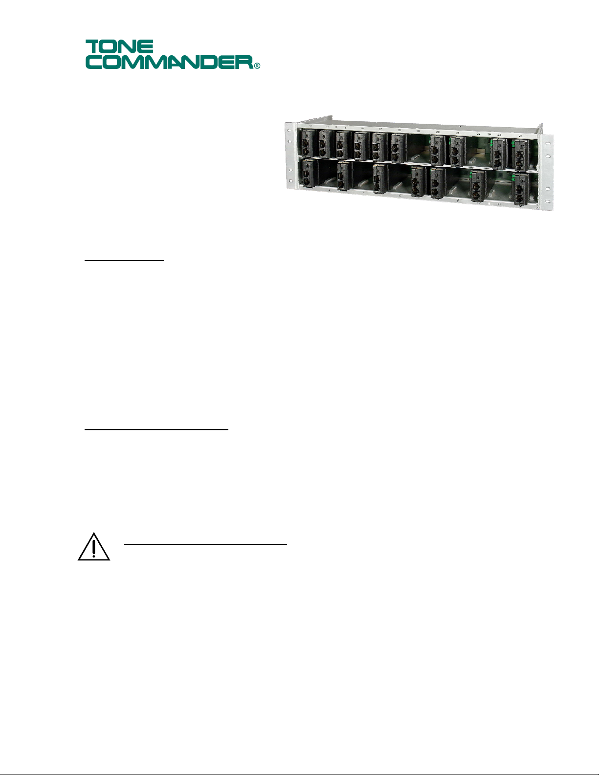
The NT1B-300 Rack houses 24 Tone Commander
NT1B-300TC ISDN Network Terminations
in a 19” rack, 23” rack, or wall mount
configuration. The rack is also compatible
with Lucent NT1B-300 NT1s.
The rack supplies power to the NT1 units
and terminal equipment connected to the
NT1s from an integral power supply. An
optional NT1-200 Battery Backup Power
Supply can be added to the NT1B-300
Rack to provide uninterrupted NT1 and
ISDN terminal power during a power failure.
Instructions
Specifications
NT1B-300 Rack with Power Supply
Capacity ......................................... 24 NT1s (48 ISDN BRI terminals)
Physical Dimensions ...................... 5.22” H x 17.25” W x 7” D (fits 19” or 23” rack, 3U rack height)
Weight ............................................ 7 lbs. without NT1s; 12 lbs. with 24 NT1s
Operating Temperature .................. 0° – 40° C (32° – 104° F)
Humidity ......................................... 5% to 95%, non-condensing
Short Circuit Protection ................... Individual self-resetting current limiting for each NT1; 20 W max. per NT1
Standards Compliance ................... UL, cUL 60950
Input Power Requirements ............. 120 VAC, 60 Hz, 5 A max.
Output Power ................................. 48-55 VDC, 240 W max.
Contents of Shipping Box
• NT1B-300 Rack with Power Supply
• 19”/23” mounting brackets (2 each)
• 10-24 x ¼” mounting bracket screws (4 each)
• Installation Instructions (this document)
Optional NT1B-300 Rack Locking Kit (Model 102933)
Important Safety Instructions
• This equipment is intended for installation in a restricted access location (dedicated equipment
rooms, equipment closets, or the like) in accordance with Articles 110-16, 110-17, and 110-18
of the National Electrical Code, ANSI/NFPA No. 70.
• Never install telephone wiring during a lightning storm.
• Never install telephone jacks in wet locations unless the jack is specifically designed for wet
locations
• Never touch uninsulated telephone wires or terminals unless the telephone line has been
disconnected at the network interface.
• Use caution when installing or modifying telephone wires.
• Do not mount the NT1B-300 Rack within 12” of a heat source.
• The socket-outlet shall be installed near the equipment and shall be easily accessible.
13-280113 Rev. B
September 2007
Page 2
Tone Commander NT1B-300 Rack Installation Instructions
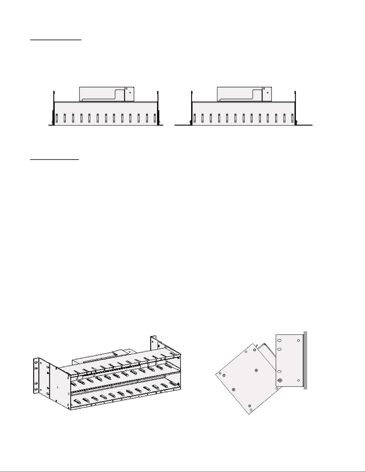
Rack Mounting
1. The NT1B-300 Rack can be mounted in a n EIA standard 19” commercial or 23” telco rack.
2. Attach the mounting brackets to the rack in a 19” or 23” mounting position as needed, using the
supplied mounting bracket screws.
3. Mount the rack to the 19” or 23” rack standards using suitable fasteners.
Bracket Positions – 19” Rack Bracket Positions – 23” Rack
Wall Mounting
Note – When mounting the NT1B-300 Rack in conjunction with a Battery Backup unit, refer to the
NT1-200 Battery Backup/NT1-200 Add-on Battery Installation Instruc tions (doc. #13-102688)
for proper mounting positions.
1. Remove all NT1 units from the rack. Unplug the power supply from the wall outlet.
2. Attach the mounting brackets to the rack in the wall mounting position, using the supplied mounting
bracket screws.
3. Fasten a ¾” plywood sheet to the wall.
4. Hold the rack up to the wall to mark the hole locations, then pre-drill the mounting holes for the rack.
When locating the rack make sure:
• the power supply fan and vents are not obstructed and there is good air flow around the rack.
• there is enough room to tilt the rack forward to access the cables on the back and enough room to
route cables. When mounted with NT1s installed, the rack extends 9.25” from the wall.
• the power cord can reach a local 120 VAC, 60 Hz, single phase grounded power outlet.
5. Attach the rack to the plywood using four suitable fasteners (such as #10x¾” pan head self-tapping
screws). A fully loaded NT1B-300 Rack weighs 12 lbs.
6. With no NT1s installed in rack, remove the top bracket mounting screw on each side of the rack and
carefully tilt the rack forward to connect ribbon cable connectors. Leave enough slack in the ribbon
cables to allow the rack to properly tilt forward for access after installation. After all cables are
connected, replace and tighten mounting screws and install the NT1s.
Wall Mount Bracket Positions Tilting Rack for Cable Access
Page 2 13-280113 Rev. B
Page 3
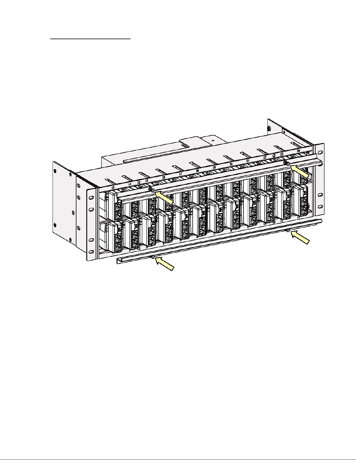
NT1B-300TC Installation
Carefully insert each NT1B-300TC into the appropriate slot in the NT1B-300 rack, with the indicator lights
oriented at the top left. The rack connectors are offset to prevent incorrect installation. Slot numbers on the
front of the rack correspond to 50-pin connector pinouts listed in Table 2. NT1s may be inserted or
removed from an operational rack without affecting the performance of other NT1 units. Make sure all NT1s
are oriented properly and fully seated in their rack connectors and verify that the termination switch settings
are correct. Refer to the NT1B-300TC installation manual (doc. # 13-280111).
To prevent unintentional removal of NT1 units, install optional locking brackets (Tone Commander Model
102933) after all NT1s are installed. Align the brackets with the mounting holes on the front of the rack and
push in the plunger on each panel fastener to secure them.
Rack with NT1B-300TCs Installed – Locking Bracket Installation
13-280113 Rev. B Page 3
Page 4

Tone Commander NT1B-300 Rack Installation Instructions
Cable Connections
Back Panel Connectors
All rack S/T and U ribbon connectors are female; male connectors are required on the cable
ends.
U lnterface
Connect each U interface pair from the network interface block into the appropriate position on the 50-pin U
interface connector on the rack rear panel. See Table 2 for connector pinouts. The rack uses self-locking
connectors; to remove a cable, use a small tool to press in the tabs on the ends of the connector.
S/T Interface
The S/T interface for each terminal can be connected one of two ways:
1. Modular jacks on the front of the NT1B-300TC units – for terminal equipment or patch panel connection
via an 8-position modular phone cord. Connecting cords must be Category 3 or higher with T568 A or
T568 B wiring. See Table 1 and the figure below for jack pinout.
Two parallel-wired jacks are provided on each NT1, for two terminals connected in a multipoint
arrangement.
2. 50-pin ribbon connectors on the rack back panel – for terminal equipment connection via a punch-down
block. See Table 2 for connector pinouts.
Connect the terminal wall jacks to 4-pair cables as shown in Table 1. Punch down the cables to the crossconnect blocks in the order shown in Table 1. Note that pairs 1-2 and 3-6 for T568A jacks are reversed
from T568B jacks.
Wire Color
Pin # Signal
5Tx- WHT-BLUWHT-BLU
4Tx+ BLU BLU
1 unused WHT-GRN WHT-ORN
2 unused GRN ORN
3 Rx+ WHT-ORN WHT-GRN
6Rx- ORN GRN
7 -48V WHT-BRN WHT-BRN
8 -48VRTN BRN BRN
T568 A
T568 B *
(AT&T)
Table 1 – Modular Jack Pinout
Page 4 13-280113 Rev. B
Page 5

Pin No. Wire Color
26 WHT-BLU TIP 1 Tx1 -Tx7 - Tx13- Tx19 -
1 BLU-WHT RING 1 Tx1+ Tx7+ Tx13+ Tx19+
27 WHT-ORN TIP 2 – – – –
2 ORN-WHT RING 2 – – – –
28 WHT-GRN TIP 3 Rx1+ Rx7+ Rx13+ Rx19+
3 GRN-WHT RING 3 Rx1 -Rx7 - Rx13 - Rx19 -
29 WHT-BRN TIP 4 -48V -48V -48V -48V
4 BRN-WHT RING 4 -48VRTN -48VRTN -48VRTN -48VRTN
30 WHT-SLT TIP 5 Tx2 -Tx8 -Tx14 -Tx20 -
5 SLT-WHT RING 5 Tx2+ Tx8+ Tx14+ Tx20+
31 RED-BLU TIP 6 – – – –
6 BLU-RED RING 6 – – – –
32 RED-ORN TIP 7 Rx2+ Rx8+ Rx14+ Rx20+
7 ORN-RED RING 7 Rx2 -Rx8 - Rx14 - Rx20 -
33 RED-GRN TIP 8 -48V -48V -48V -48V
8 GRN-RED RING 8 -48VRTN -48VRTN -48VRTN -48VRTN
34 RED-BRN TIP 9 Tx3 -Tx9 -Tx15 -Tx21 -
9 BRN-RED RING 9 Tx3+ Tx9+ Tx15+ Tx21+
35 RED-SLT TIP 10 – – – –
10 SLT-RED RING 10 – – – –
36 BLK-BLU TIP 11 Rx3+ Rx9+ Rx15+ Rx21+
11 BLU-BLK RING 11 Rx3 -Rx9 - Rx15 - Rx21 -
37 BLK-ORN TIP 12 -48V -48V -48V -48V
12 ORN-BLK RING 12 -48VRTN -48VRTN -48VRTN -48VRTN
38 BLK-GRN TIP 13 Tx4 -Tx10 -Tx16 -Tx22 -
13 GRN-BLK RING 13 Tx4+ Tx10+ Tx16+ Tx22+
39 BLK-BRN TIP 14 – – – –
14 BRN-BLK RING 14 – – – –
40 BLK-SLT TIP 15 Rx4+ Rx10+ Rx16+ Rx22+
15 SLT-BLK RING 15 Rx4 - Rx10 - Rx16 - Rx22 -
41 YEL-BLU TIP 16 -48V -48V -48V -48V
16 BLU-YEL RING 16 -48VRTN -48VRTN -48VRTN -48VRTN
42 YEL-ORN TIP 17 Tx5 -Tx11 -Tx17 -Tx23 -
17 ORN-YEL RING 17 Tx5+ Tx11+ Tx17+ Tx23+
43 YEL-GRN TIP 18 – – – –
18 GRN-YEL RING 18 – – – –
44 YEL-BRN TIP 19 Rx5+ Rx11+ Rx17+ Rx23+
19 BRN-YEL RING 19 Rx5 - Rx11 - Rx17 - Rx23 -
45 YEL-SLT TIP 20 -48V -48V -48V -48V
20 SLT-YEL RING 20 -48VRTN -48VRTN -48VRTN -48VRTN
46 VlO-BLU TIP 21 Tx6 -Tx12 -Tx18 -Tx24 -
21 BLU-VlO RING 21 Tx6+ Tx12+ Tx18+ Tx24+
47 VlO-ORN TIP 22 – – – –
22 ORN-VlO RING 22 – – – –
48 VlO-GRN TIP 23 Rx6+ Rx12+ Rx18+ Rx24+
23 GRN-VIO RING 23 Rx6 - Rx12 - Rx18 - Rx24 -
49 VIO-BRN TIP 24 -48V -48V -48V -48V
24 BRN-VIO RING 24 -48VRTN -48VRTN -48VRTN -48VRTN
50 VlO-SLT – – – – –
25 SLT-VlO – – – – –
U Lines
1-24
S/T Ports
1-6
S/T Ports
7-12
S/T Ports
13-18
S/T Ports
19-24
Table 2 – 50-pin Ribbon Connector Pinouts
13-280113 Rev. B Page 5
Page 6

Tone Commander NT1B-300 Rack Installation Instructions
Power
Rack Power Supply
1. Verify that the power output cable (red and black wires) is plugged into the rack’s POWER connect or.
2. Plug the power cord into a local 120 VAC, 60 Hz, single phase power outlet.
Battery Backup Power Supply
Refer to the NT1-200 Battery Backup Installation Instructions (doc. #13-102688) for Backup Battery power
supply installation.
ISDN Terminal Power
ISDN terminals connected to the NT1s installed in the rack are powered from the NT1B-300 Rack power
supply. Terminal power can be provided by either of the following methods:
PS-2 – Direct power feed on Terminal jack pin 7 (-) and pin 8 (+), approximately 4.5 watts average per
terminal for a fully loaded rack (240 watts maximum per rack).
PS-1 – Phantom power feed over the transmission pairs, Terminal jack pins 3/6 (+) and pins 4/5 (-), 4 watts
maximum per NT1 circuit.
Power connections to each NT1 are individually short circuit protected.
Power Up Test
Refer to the NT1B-300TC installation manual (doc. # 13-280111) for power up test information.
Service
Repair of the NT1B-300 Rack and NT1B-300TC must be done by Tone Commander. Prior to equipment
removal, call Tone Commander Customer Technical Support for assistance in determi ning the source of
the problem. This critical action can often prevent needless removal of equipment and subsequent
customer inconvenience.
Tone Commander
Customer Technical Support Department
11609 49th Place West
Mukilteo, WA 98275-4255 USA
Phone: (425) 349-1000
(800) 524-0024
Fax: (425) 349-1010
E-mail: tech@tonecommander.com
Web: www.tonecommander.com
Tone Commander is committed to meeting the product needs of our customers. Please write or call us with
any suggestions for improvement.
Page 6 13-280113 Rev. B
Page 7

FCC Requirements
The Tone Commander Models NT1B-300 Rack and NT1B-300TC comply with Part 68 of the FCC Rules.
The label affixed to this equipment contains, among other information, the FCC Registration for this
equipment. You must, upon request, provide this information to your telephone company.
The following jacks must be ordered from the telephone company in order to interconnect this product with
the public communication network: RJ21X.
If your NT1B-300 Rack or NT1B-300TC causes harm to the telephone network, the Telephone Company
may discontinue your service temporarily. if possible, they will notify you in advance. But if advance notice
is not practical you will be notified as soon as possible. You will be informed of your right to file a complaint
with the FCC.
Your telephone company may make changes in its facilities, equipment, operations or procedures that
could affect the proper functioning of your equipment. If they do, you will be notified in advance to give you
an opportunity to maintain uninterrupted telephone service.
If you have trouble with the NT1B-300 Rack and NT1B-300TC, contact us at the address listed on page 6
of this manual for information on obtaining service or repairs. The telephone company may ask that you
disconnect the telephone from the network until the problem has been corrected or until you are sure that
the equipment is not malfunctioning.
The Tone Commander NT1B-300 Rack and NT1B-300TC have been tested and found to comply with the
limits for a Class B digital device, pursuant to Part 15 of the FCC Rules. These limits are designed to
provide reasonable protection against harmful interference when the equipment is operated in a residential
environment. This equipment generates, uses, and can radiate radio frequency energy and, if not installed
and used in accordance with the instruction manual, may cause harmful interference to radio
communications. However, there is no guaranty that interference will not occur in a particular installation. If
this equipment does cause harmful interference to radio or television reception, which can be determined
by turning the equipment off and on, the user is encouraged to try to correct the interference by one of the
following measures:
• Where it can be done safely, re-orient the receiving television or radio antenna.
• To the extent possible, increase the separation between the telephone equipment and
the television, radio, or other equipment.
• If your telephone equipment runs on AC power, plug your product into an AC outlet that
is not on the same circuit as the one used by your radio or television receiver.
13-280113 Rev. B Page 7
Page 8

Tone Commander NT1B-300 Rack Installation Instructions
Tone Commander Product Warranty
For a period of one year from date of dealer purchase, but not to exceed 16 months from date of
manufacture, Tone Commander Systems, Inc. (Tone Commander) warrants its products to be free from
defects in material and workmanship under conditions of normal use and service. Tone Commander shall,
at its option, repair or replace any defective product which, in its opinion, has not been misused, damaged,
or improperly installed.
Repair or replacement under this warranty will be performed at Tone Commander's factory. Authorization
must be obtained from Tone Commander prior to returning a product for repair. Freight must be prepaid for
all units returned to Tone Commander. Units repaired under warra nty will be shipped UPS Ground (or
equivalent), freight prepaid by Tone Commander.
Products that are older than the warranty period, but less than 7 years old, or still manufactured by Tone
Commander may be repaired at the factory for a flat rate charge. Repaired out-of-warranty units are
warranted for 90 days from the date of repair.
The repair or replacement of a product under this warranty represents the entire obligation of Tone
Commander; Tone Commander shall not be liable for any special or consequential damages resulting from
or caused by any defect, failure, incapacity or malfunction of any of its products.
The foregoing express warranty is in lieu of all other warranties, express or im plied,
including, but not limited to any implied warranty of merchantability, fitness, or adequacy
for any purpose or use, quality, productiveness or capacity; Tone Commander, to the
extent permitted by law, hereby disclaims all such other warrant ies.
Page 8 13-280113 Rev. B
 Loading...