

Page 1
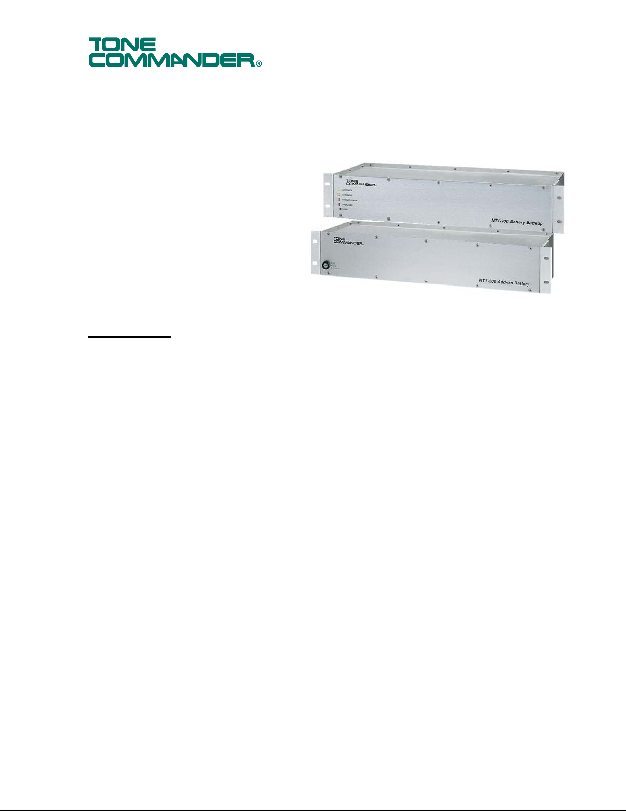
The Battery Backup units for Tone
6
y
Commander NT1 Racks and ISDN Power
Supplies provide backup NT1 and terminal
power (PS1 and PS2) during a power failure.
The NT1-200 Battery Backup is used with the
NT1B-300 Rack, NT1-220 Rack, and PS-50
ISDN Power Supply; the NT1-200/296 version
is used with the NT1-296 Rack. An optional
Add-on Battery is available to increase the
duration of backup power.
Specifications
NT1-200, NT1-200/29
Battery Backup
NT1-200 Add-on Batter
NT1-200, NT1-200/296 Battery Backup
Built-in management circuit (protection, charging, and monitor display).
Output Voltage ............................... 42 - 55 VDC
Charging Current ............................ 700 mA max. (shared with the NT1-200 Add-on Battery if present)
Battery Capacity ............................. 7 AH
Overcurrent Protection ................... 6.25 A, 250 V Slow Blow fuse
Physical Dimensions ...................... 3.5” H x 17.3” W x 6.2” D
Weight ............................................ 27 lbs.
Operating Temperature .................. 0° - 40° C (32° - 104° F) Note: Battery life decreases above 20° C (68° F)
Humidity ......................................... 5% to 95%, non-condensing
Alarm Contacts ............................... 48 VDC @ 0.5A max. (resistance load)
Battery Type ................................... Sealed lead-acid, maintenance-free
In-service Battery Life ..................... 3 - 6 years @ 20° C (68° F)
NT1-200 Add-on Battery
Output Voltage ............................... 42 - 55 VDC
Charging Current ............................ shared with NT1-200(/296) Battery Backup
Battery Capacity ............................. 7 AH
Overcurrent Protection ................... 6.25 A, 250 V Slow Blow fuse
Physical Dimensions ...................... 3.5” H x 17.3” W x 6.2” D
Weight ............................................ 27 lbs.
Operating Temperature .................. 0° - 40° C (32° - 104° F) Note: Battery life decreases above 20° C (68° F)
Humidity ......................................... 5% to 95%, non-condensing
Battery Type ................................... Sealed lead-acid, maintenance-free
In-service Battery Life ..................... 3 - 6 years @ 20° C (68° F)
13-102688 Rev. G
February 2006
Page 2
Important Safety Instructions
• To be installed only in restricted access areas (dedicated equipment rooms, equipment clo sets,
or the like) in accordance with Articles 110-16, 110-17, and 110-18 of the National Electrical
Code, ANSI/NFPA No. 70.
• Never install telephone wiring during a lightning storm.
• Never install telephone jacks in wet locations unless the jack is specifically designed for wet
locations.
• Never touch uninsulated telephone wires or terminals unless the telephone line has been
disconnected at the network interface.
• Use caution when installing or modifying telephone wires.
• Do not mount the NT1-200(/296) Battery Backup or the NT1-200 Add-on Battery within 12” of a
heat source.
Contents of Shipping Box
NT1-200, NT1-200/296 Battery Backup NT1-200 Add-on Battery
(1) Battery Backup (1) NT1-200 Add-on Battery
(1) Interconnecting “Y” Cable (2) Mounting brackets
(2) Mounting brackets (4) Mounting bracket screws
(4) Mounting bracket screws (1) Fuse cap and fuse
(1) Fuse cap and fuse
Installation
Rack Mounting
The NT1-200(/296) Battery Backup and the NT1-200 Add-on Battery can be mounted in an EIA standard
19” commercial or 23” Telco rack.
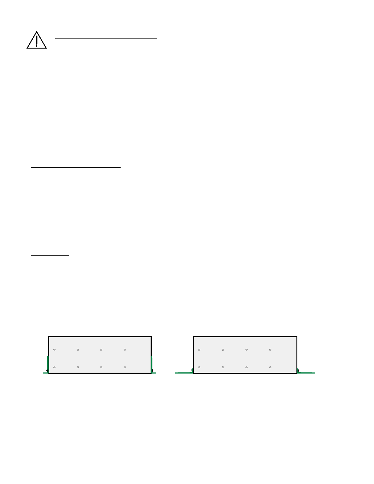
1. Attach the mounting bra c kets to the Battery Backup and/or Add -on Battery in the 19 ” or 23” mounting
position as needed, using the supplied mounting bracket screws (see Figure 1).
2. Mount the battery units to the 19” or 23” rack using suitable fasteners.
Refer to Figures 2-5 for mounting positions and required clearances.
Bracket Positions – 19” Rack Bracket Positions – 23” Rack
Figure 1 – Rack Mount Bracket Positions
Page 2 Tone Commander NT1-200, NT1-200/296 Battery Backup / NT1-200 Add-on Battery
Page 3

13 "
1" min.
clearance
3.5 "
1.75 "
3.5 "
3.5 "
19 "
Figure 2 – Rack Mounting with PS-50
15 "
1" min.
clearance
5.25 "
1.75 "
3.5 "
3.5 "
19 "
Figure 3 – Rack Mounting with NT1B-300 Rack
Tone Commander NT1-200, NT1-200/296 Battery Backup / NT1-200 Add-on Battery Page 3
Page 4

1" min.
clearance
5.25 "
15 "
1" min.
clearance
1.75 "
3.5 "
3.5 "
19 "
Figure 4 – Rack Mounting with NT1-296 Rack
5.25 "
15 "
1.75 "
3.5 "
3.5 "
19 "
Figure 5 – Rack Mounting with NT1-220 Rack
Page 4 Tone Commander NT1-200, NT1-200/296 Battery Backup / NT1-200 Add-on Battery
Page 5

Wall Mounting
1. Attach mounting bra c kets to the Battery Backup and/or Add-on Battery in the wall mounting position
using the supplied mounting bracket screws (see Figure 6).
2. Fasten a plywood sheet to the wall, ¾” minimum thickness. Do not mount the rack or battery units
directly to drywall material.
3. Mark and pre-drill the mounting holes for the battery backup and/or add-on battery.
Refer to Figures 7–10 for hole locations and required clearances.
4. Attach the battery backup an d/or add-on battery to the plywood using four suitable fasteners.
The Battery Backup and Add-on Battery must be fastened securely;
these units weigh 27 lbs. each!
clearance
14 " min.
19.5 " max.
1" min.
2.5 " min.
3.5 "
8 " max.
3.5 "
3.5 "
Figure 6 – Wall Mount Bracket Positions
1.75 "
4.25 "
min.
1.75 "
1.75 "
1.75 "
18.25 "
19 "
Figure 7 – Wall Mounting with PS-50
Tone Commander NT1-200, NT1-200/296 Battery Backup / NT1-200 Add-on Battery Page 5
Page 6

1" min.
clearance
15.00 "
1" min.
clearance
5.25 "
1.75 "
3.5 "
3.5 "
18.25 "
19 "
Figure 8 – Wall Mounting with NT1B-300 Rack
4 "
3.25 "
1.75 "
1.75 "
1.75 "
18.47 "
3.5 "
5.25 "
1.75 "
3.5 "
3.5 "
4 "
3.25 "
1.75 "
1.75 "
1.75 "
18.25 "
19 "
Figure 9 – Wall Mounting with NT1-296 Rack
Page 6 Tone Commander NT1-200, NT1-200/296 Battery Backup / NT1-200 Add-on Battery
Page 7

20.5 "
19 " 18.25 "
4 "
9.75 "
1.75 " 1.75 " 1.75 "
Figure 10 – Wall Mounting with NT1-220 Rack
Tone Commander NT1-200, NT1-200/296 Battery Backup / NT1-200 Add-on Battery Page 7
Page 8

Cable Connection
To avoid power supply connector damage due to load inrush currents, make sure all NT1s are removed
from the rack before cable connections are made.
Refer to Figure 11.
1. Make sure that no NT1s are inserted in the rack.
2. Unplug the power supply output cable from the NT1 rack or PS-50.
3. Plug the 4-pin connector on the “Y” cable into the upper connector on the back panel of the Battery
Backup.
4. Connect the short wires on the “Y” cable to the power supply output cable female connector.
5. Plug the long wires on the “Y” cable into the NT1B-300 Rack, NT1-296 Rack, NT1-220 Rack, or PS-50
“POWER” connector.
6. Insert the fuse into the fuse holder on the Battery Backup front panel and secure with the supplied fuse
cap. The Backup Power indicator will light.
7. Connect AC power to the power supply.
8. Install NT1s in the rack.
Add-on Battery
Refer to Figure 11.
1. Insert the fuse into the fuse holder on the Add-on Battery front panel and secure with the supplied fuse
cap.
2. Plug the Add-on Battery wires into the center connector on the back panel of the Battery Backup (AC
power may be connected).
Figure 11 – Battery Connections
Page 8 Tone Commander NT1-200, NT1-200/296 Battery Backup / NT1-200 Add-on Battery
Page 9

Alarm
The alarm modular jack provides two relay contact circuits for alarm monitoring. Make sure that you do not
exceed the relay contact rating of 48 VDC @ 0.5 A (resistive). During AC power loss, pins 2 and 5 are
shorted and pins 3 and 4 are open as shown in Figure 12.
Figure 12 – Alarm (6 Position Modular Jack)
Status Indicators
The Battery Backup has four status indicator LEDs on the front panel.
Status Indicator LED Description
AC Power
(green)
Charging
(Yellow)
Backup Power
(Red)
Overload
(Red)
all LEDs off Batteries are fully discharged, or a fuse is blown.
Battery Backup is connected to the rack and the rack is currently being fed
from the power supply.
The Battery Backup (and the Add-on Battery, if present) are currently being
charged. Does not light when the rack is on backup power.
The rack is currently being powered by the Battery Backup (and the Add-on
Battery, if present).
Too much power is being drawn from the Backup Battery and/or the Add-on
Battery. Investigate and remove the fault condition.
Tone Commander NT1-200, NT1-200/296 Battery Backup / NT1-200 Add-on Battery Page 9
Page 10

Service
Repair of the NT1-200 or NT1-200/296 Battery Backup and the NT1-200 Add-on Battery must be done by
Tone Commander. Prior to equipment removal, call Tone Commander Customer Service for assistance in
determining the source of the problem. This critical action can often prevent needless removal of
equipment and subsequent customer inconvenience.
Tone Commander
Technical Support Department
11609 49th Place West
Mukilteo, WA 98275-4255 USA
Phone: (425) 349-1000
(800) 524-0024
Fax: (425) 349-1010
E-mail: tech@tonecommander.com
Web: www.tonecommander.com
Tone Commander is committed to meeting the product needs of our customers. Please write or call us with
any suggestions for improvement.
Tone Commander Product Warranty
For a period of one year from date of dealer purchase, but not to exceed 16 months from date of manufacture, Tone
Commander Systems, Inc. (Tone Commander) warrants its products to be free from defects in material and
workmanship under conditions of normal use and service. Tone Commander shall, at its option, repa ir or replace any
defective product which, in its opinion, has not been misused, damaged, or improperly installed.
Repair or replacement under this warranty will be performed at Tone Commander's factory. Authorization must be
obtained from Tone Commander prior to returning a product for repair. Freight must be prepaid for all units retur ne d to
Tone Commander. Units repaired under warranty will be shippe d UPS Ground (or equivalent), freight prepaid by Tone
Commander.
Products that are older than the warranty period, but less than 7 years old, or still manufactured by Tone Commander
may be repaired at the factory for a flat rate charge. Repaired out-of-warranty units are warranted for 90 days from the
date of repair.
The repair or replacement of a product under this warranty represents the entire obligation of T one Commander; Tone
Commander shall not be liable for any special or consequential damages resulting from or caused by any defect,
failure, incapacity or malfunction of any of its products.
The foregoing express warranty is in lieu of all other warranties, express or implied, including but not
limited to any implied warranty of merchantability, fitness, or adequacy for any purpose or use,
quality, productiveness or capacity; Tone Commander, to the extent permitted by law, hereby
disclaims all such other warranties.
Page 10 Tone Commander NT1-200, NT1-200/296 Battery Backup / NT1-200 Add-on Battery
 Loading...