

Page 1
EE991111 RReessppoonnssee SSeerrvveerr
Teo Technologies
11609 49th Place West
Mukilteo, WA 98275-4255
(800) 524-0024 (425) 349-1000
Fax (425) 349-1010
www.teotech.com
9911445
5
IInnssttaallllaattiioonn IInnssttrruuccttiioonnss
13-280133 Rev. C
May 2014
Page 2

Teo E911 Response Server 9145 Installation Instructions
© 2014, Teo Technologies. All rights reserved.
Page 2 13-280133 Rev. C
Page 3

C
o
n
t
e
n
t
s
C
o
n
t
e
C
o
n
Introduction ................................................................................................................................. 5
Product Description .............................................................................................................. 6
Operational Overview .......................................................................................................... 8
Front Panel Indicators and Switches ................................................................................... 9
Installation ................................................................................................................................. 11
Installation Overview .......................................................................................................... 11
Safety Guidelines and General Installation ....................................................................... 12
Rack Mounting .................................................................................................................... 14
Connecting to the LAN ....................................................................................................... 19
Connecting to the PBX PRI-U Port ..................................................................................... 20
Connecting to the Telco Network PRI-N Port .................................................................... 22
Configuring the PBX ........................................................................................................... 24
Configuring the Administration PC ................................................................................... 24
Reporting Devices............................................................................................................... 25
Monitoring and Recording 911 Calls ................................................................................. 27
Power .................................................................................................................................. 28
n
t
e
n
t
s
t
s
Initial Configuration .................................................................................................................. 29
Joining the Local Domain .................................................................................................. 29
Remote Monitor Configuration .......................................................................................... 34
System Administration ............................................................................................................. 35
Using the System Administration Program ...................................................................... 36
Using the Event Log Viewer ............................................................................................... 53
System Operation ..................................................................................................................... 57
Overview ............................................................................................................................. 57
Line Status Indicators ......................................................................................................... 58
Switches .............................................................................................................................. 60
Reporting ............................................................................................................................ 61
Call Monitoring and Recording .......................................................................................... 62
Alarms ........................................................................................................................................ 63
Overview ............................................................................................................................. 63
Alarm Records .................................................................................................................... 63
File Alarms .......................................................................................................................... 64
Hardware Alarms ................................................................................................................ 65
ISDN PRI-U Alarms ............................................................................................................. 66
ISDN PRI-N Alarms ............................................................................................................. 67
Status Messages ................................................................................................................. 68
Alarm Status ....................................................................................................................... 68
Testing ....................................................................................................................................... 69
Verifying Proper Operation ................................................................................................ 69
Generating Test Calls ......................................................................................................... 70
13-280133 Rev. C Page 3
Page 4

Teo E911 Response Server 9145 Installation Instructions
Generating Alarms .............................................................................................................. 71
PBX Configuration Testing ................................................................................................. 72
Troubleshooting ......................................................................................................................... 73
Status Indicators ................................................................................................................. 73
Unable to Connect with Administration PC ....................................................................... 76
Reporting Devices Do Not Work......................................................................................... 79
Specifications ............................................................................................................................. 83
Service and Warranty ................................................................................................................ 85
Service ................................................................................................................................. 85
Teo Product Warranty ......................................................................................................... 86
Safety and Regulatory Requirements ...................................................................................... 87
Cautions ............................................................................................................................... 87
FCC Part 15 .......................................................................................................................... 87
FCC Part 68 .......................................................................................................................... 88
National Electrical Code ...................................................................................................... 88
Glossary ...................................................................................................................................... 89
Page 4 13-280133 Rev. C
Page 5

I
n
t
r
o
d
u
c
t
i
o
n
I
n
t
r
o
d
u
c
t
I
n
t
r
o
d
u
Businesses, shared tenant services, college campuses, and other institutions are
sometimes distributed geographically among several locations or dispersed over a large
area with their telephone extensions linked to a single Private Branch Exchange (PBX)
switch. In such a geographic environment, telephone extensions are often not in the same
physical location as the PBX. They may be located on different floors, buildings or
campuses.
Most telephone systems are configured such that only the main PBX Telephone Number
and its location information are sent to emergency services when 911 is dialed.
Consequently, the exact physical location of the emergency must be determined by
questioning the caller. When the caller does not know or cannot respond, critical time is
spent searching for the person in distress when emergency services arrive on the scene.
The Teo E911 Response Server 9145 resolves these issues. The 9145 contains a station
data table that has an exact location description for each PBX station set. Every time any
PBX phone is used to dial 911, the 9145 ensures that the correct ANI (Automatic Number
Identification) is sent to the PSAP 911 Call Taker and then it instantly sends a text message
alert to every need-to-know person you want notified about the emergency event. In a true
emergency every second counts; your safety staff members, security team, key
management personnel, and anyone else instrumental in your Emergency Procedures Plan
will be appropriately notified well before the public Emergency Responders arrive. The
E911 Response Server 9145 provides audio recording and real-time audio monitoring.
Prank 911 call activity will be instantly identified and you will have the opportunity to take
corrective action seconds after the prank call is originated. This is also a valuable tool for
validating when an abandoned 911 call has occurred.
c
i
t
o
n
o
n
i
The E911 Response Server 9145 is designed for long term reliability and nonstop service,
even if hardware maintenance is ever required. The system is designed with redundant
hot-swappable power supplies and redundant hot-swappable drives that may be replaced
while the system remains in a fully operational mode.
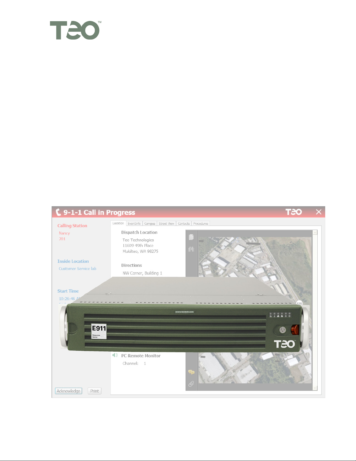
The Emergency alert notifications include PC pop-up screen views with both text and
graphic presentation containing calling party information, location information, who’s been
notified, direction and map information, as well as emergency response procedure
documentation, all customizable. Alerts about emergency calls will generate audible
attention-getting sound and all recipients will get detailed text and supporting information.
The alerting devices can be PC screens, cell phones, pagers, or even alerts via email
messaging. Everyone who needs to know will be alerted.
13-280133 Rev. C Page 5
Page 6
Teo E911 Response Server 9145 Installation Instructions
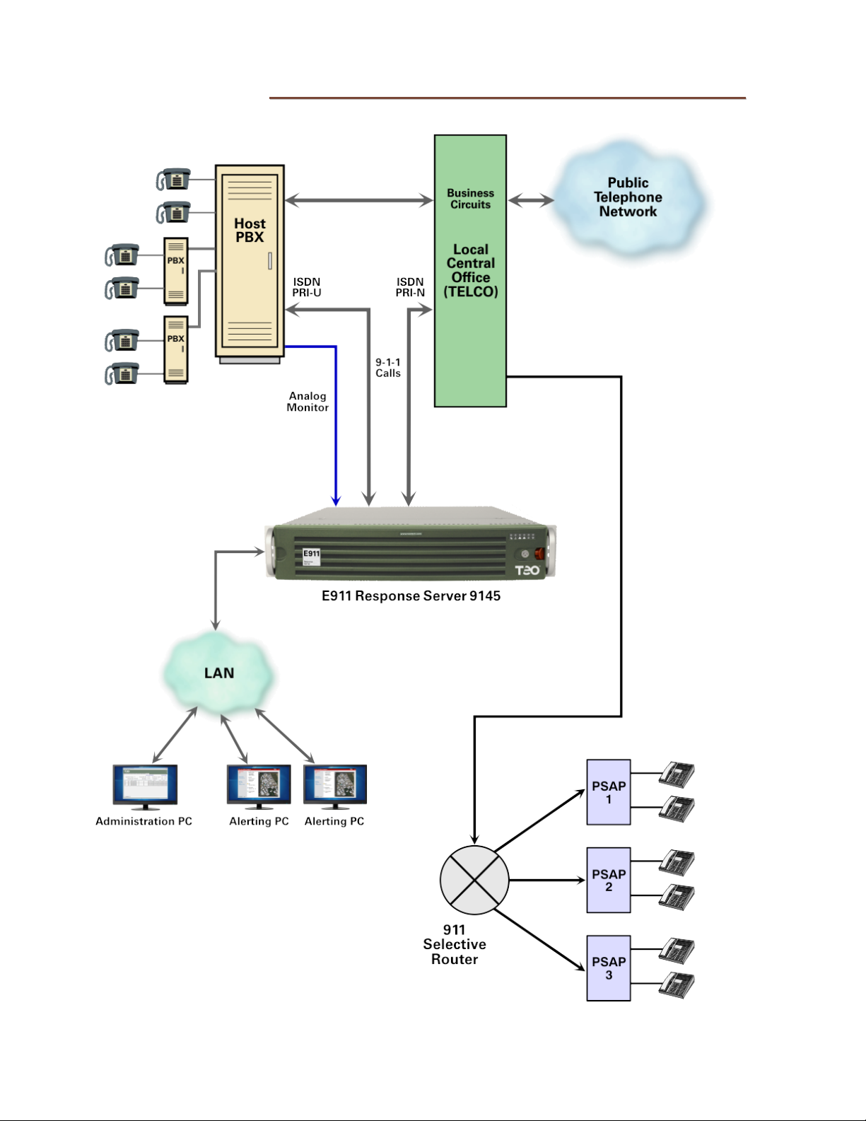
PPrroodduucctt DDeessccrriippttiioonn
E911 Response Server 9145 Typical Installation
Page 6 13-280133 Rev. C
Page 7

Introduction
SSyysstteemm FFeeaattuurreess
The E911 Response Server 9145 provides Enhanced 911 (E911) connectivity to any PBX
capable of supporting an ISDN-PRI connection. The 9145 provides the following features:
• Direct connection to PBX and Telco ISDN-PRI ports with no other interface
equipment required.
• Windows PC Administration Program with help to support system configuration and
maintenance.
• Internal database to translate/change PBX station numbers to any 10-digit (ANI).
• Supports text messaging cellular telephones, alphanumeric pagers, printers, and PC
“pop-up” screens to report 911 call activity and system alarms.
• An internal log file records and date/time stamps call and alarm records.
• Supports LAN access for remote system administration.
• Built in self-test modes and operational monitoring functions.
• Multicolored front panel indicators show system status, call activities and alarms.
• Fuseless (solid state) line protection on all system interfaces.
• Redundant power supplies.
• Redundant drives.
• Two recording ports are supplied with all systems; two additional recording ports
can be ordered.
• Up to four monitoring ports can be ordered.
• Installs in a four post server rack (2U rack height).
SSyysstteemm CCoonnffiigguurraattiioonnss
The 9145 E911 Response Server can be purchased in a variety of factory configurations.
• PBX Stations (100 – 60,000, in 100 station increments)
• Ports, up to (6) total:
o (2 or 4) Recording Ports
o (0, 2, or 4) Monitor Ports
13-280133 Rev. C Page 7
Page 8

Teo E911 Response Server 9145 Installation Instructions
OOppeerraattiioonnaall OOvveerrvviieeww
The 9145 monitors calls that originate from the PBX towards the Telco network. When a
911 call is detected, the 9145 changes or passes through the 911 network-bound callers
telephone number (ANI) according to a user programmed database (station table).
The PBX must be programmed to route 911 calls to the ISDN-PRI port that is connected to
the 9145. Once a caller using the PBX goes off hook and dials 911, the calling party's 3- to
10-digit station number is sent to the 9145 via the ISDN-PRI Data Channel (D Channel). This
number is then used as the input to the internal station table database to retrieve the
translated 10-digit ANI for the caller's station.
The 10-digit translated ANI is forwarded via the Telco ISDN-PRI D channel toward the 911
network. The ANI is sent to the 911 Call Taker and the Automatic Location Information (ALI)
is retrieved from the Telco ALI database using the received ANI. Upon answer of the 911
call, the voice connection is then completed between the PBX caller and the 911 Call Taker.
The 9145 generates a call start record at the time it receives the 911 call from the ISDN-PRI
connection. The call start record is recorded in the system's Log file and, if programmed to
do so, the system will report the event to PC Popup Displays and other reporting devices.
When the 911 call ends, the 9145 will generate a call disconnect record that is also logged
and reported. The call disconnect record is sent to the reporting devices.
The 9145 also has the ability to “mask” the outgoing caller ID on non-911 calls. If call
masking is enabled, the caller ID sent for non-911
or pilot number. Sensitive areas such as school classrooms may want a pilot number or
administration number presented as the caller ID for non-911 calls.
calls may be replaced with another local
Page 8 13-280133 Rev. C
Page 9

Introduction
FFrroonntt PPaanneell IInnddiiccaattoorrss aanndd SSwwiittcchheess
The E911 Response Server has two switch and indicator areas on the front panel.
FFrroonntt BBeezzeell RReemmoovvaall
Press the red lever left to unlatch the front bezel, and then pull the bezel forward to
remove. The bezel may be locked (using the included key) to prevent removal.
LLiinnee SSttaattuuss CCoonnttrrooll PPaanneell
This control panel has indicators for line and internal processor functions, and a self test
switch.
STATUS – indicates that the processor and software are functioning correctly.
PRI-U (PBX) – shows the communication status of the ISDN PRI-U → PBX port.
PRI-N (CO) – shows the communication status of the ISDN PRI-N → Central Office port.
ALARM – indicates an alarm condition.
911 CALL IN PROGRESS – indicates 911 call activity.
SELF TEST Switch – initiates a test of the E911 Response Server (page 69).
Switches 2 – 4 are reserved for factory use only; they should be left in the OFF (down)
position.
13-280133 Rev. C Page 9
Page 10

Teo E911 Response Server 9145 Installation Instructions
CCoommppuutteerr//NNeettwwoorrkk CCoonnttrrooll PPaanneell
The indicators on this panel show the status of the internal computer system and network
connections. The power switch and reset button are also located here.
Power Failure –flashing indicates a failure in either of the two power supplies.
Overheat/Fan Fail –flashing indicates a fan failure. Continuously on (not
flashing) indicates an overheat condition, which may be caused by cables
obstructing the airflow in the system or the ambient room temperature being too
warm.
NIC 2 – flashing indicates network activity on LAN interface 2.
NIC 1 – flashing indicates network activity on LAN interface 1.
HDD – flashing indicates drive activity.
Power – indicates that power is being supplied to the system's power supply
units. This indicator should normally be illuminated when the system is
operating.
Reset Button – press to force a reboot of the system.
Power Button – used to apply or remove power from the power supplies to the
server system.Turning off system power with this button removes the main
power but keeps standby power supplied to the system.Therefore, you must
unplug system power cords before servicing.
Page 10 13-280133 Rev. C
Page 11

I
n
s
t
a
l
l
a
t
i
o
n
I
n
s
t
a
l
l
a
t
I
n
s
t
a
l
IInnssttaallllaattiioonn OOvveerrvviieeww
Refer to the illustration on page 6 for the typical installation environment. The 9145 is
connected between the PBX network and the Telco network and is typically located in the
PBX room.
The following steps must be performed before system installation is complete:
1. Mount the 9145 in the rack.
2. Connect the 9145 to the LAN.
3. Connect both the PBX and Telco ISDN-PRI ports to the 9145.
4. Configure the PBX to route calls from a test number (e.g. ‘711’) to the ISDN-PRI port.
5. Configure the Administration PC.
6. Connect and configure desired Reporting Devices.
i
l
a
t
o
n
o
n
i
7. Connect and configure optional monitor ports.
8. Connect AC power.
9. Configure the 9145 to join the network domain.
10. Initiate an administration session between the Administration PC and the 9145.
11. Using the Administration PC, create and send valid Configuration and Station Table
data to the 9145.
12. Verify proper operation by observing status indicators and checking for alarms.
13. Using a test number (e.g. ‘711’), place a test call from the PBX to the system.
14. On the Administration PC, use the Log Viewer to verify the correct calling station
number and ANI number.
15. Configure the PBX to route 911 calls to the ISDN-PRI port.
16. Dial ‘911’ to place a live test call to the 911 Call Taker.
17. Communicate with the 911 Call Taker to obtain the ANI and verify voice call quality.
18. Connect, configure and test desired Reporting Devices.
19. Connect, configure and test optional monitor ports.
20. Verify PBX Overflow (Alternate Routing) and remote PBX 911 call operation.
To ensure proper operation of the 9145, ALL of the above tasks must be completed
before placing the unit into operation. Make sure that the Configuration and Station
data is set up correctly prior to sending to the 9145, and perform all tests described in
the Testing section.
Ongoing administration must be performed to keep the 9145 configuration current
with any changes to the telephone system.
Teo’s liability is limited to replacement of a defective 9145 as stated in the Product
Warranty (page 85).
13-280133 Rev. C Page 11
Page 12

Teo E911 Response Server 9145 Installation Instructions
SSaaffeettyy GGuuiiddeelliinneess aanndd GGeenneerraall IInnssttaallllaattiioonn
SSaaffeettyy GGuuiiddeelliinneess
Prior to installing the system, read and follow all safety guidelines. The 9145 must be
installed only by qualified personnel. The following warnings and cautions must be
observed during installation and operation of the system.
Never install telephone wiring during a lightning storm.
Never install telephone jacks in wet locations unless the jack is
specifically designed for wet locations.
Never touch uninsulated telephone wires or terminals unless the
telephone line has been disconnected at the network interface.
Do not attach or staple the AC power cord to any building surface.
WARNING!
RISK OF ELECTRICAL SHOCK!
CAUTION!
To reduce the risk of fire, use only No. 26 AWG UL Listed or CSA
Certified Telecommunications Line Cord for all connections to the
telephone network.
CAUTION!
This equipment shall be installed only in restricted access areas in
accordance with Articles 110-16, 110-17 and 110-18 of the National
Electrical Code ANSI/NFPA No. 70–1987 and any local codes as
required.
Page 12 13-280133 Rev. C
Page 13

Installation
UUnnppaacckk aanndd IInnssppeecctt tthhee EEqquuiippmmeenntt
Check the components for damage that might have occurred during shipment. If any
equipment is damaged, contact the carrier. Verify that the shipment is complete by
comparing the shipped equipment with the shipping list.
The following items are included:
(1) E911 Response Server 9145
(2) Power cords
(2) Brackets for 19" rack mounting
(4) Mounting bracket thumbscrews
(2) Rack inner rails
(2) Rack inner rail extensions
(6) Rack inner rail screws
(2) Rack long (front) outer rails
(2) Rack short (rear) outer rails
(1) Front bezel key
(1) Installation Instructions (this manual)
(1) CD with Administration Program, Event Log Viewer, and Alert Responder software
LLooccaattiioonn RReeqquuiirreemmeennttss
The 9145 installation requires a clean, secure room on the customer premises. The room
must have adequate ventilation and room for front and rear panel access. The 9145 must
only be installed in dedicated equipment rooms or restricted areas when the equipment is
mounted to a wall (backboard) or equipment rack, and it must be installed per articles 11515, 110-17 and 110-18 of the National Electrical Code ANSI/MFPA.
The 9145 must be mounted in a 19" equipment rack.
EEnnvviirroonnmmeennttaall CCoonnssiiddeerraattiioonnss
The 9145 is designed to operate within the following environmental limits:
Operating Temperature: 0° to 40° C (outside the chassis)
Operating Humidity: Up to 95% (non-condensing)
13-280133 Rev. C Page 13
Page 14

Teo E911 Response Server 9145 Installation Instructions
RRaacckk MMoouunnttiinngg
RRaacckk PPrreeccaauuttiioonnss
• Ensure that the leveling jacks on the bottom of the rack are fully extended to the
floor with the full weight of the rack resting on them.
• In single rack installation, stabilizers should be attached to the rack.
• In multiple rack installations, the racks should be coupled together.
• Always make sure the rack is stable before extending a component from the rack.
• You should extend only one component at a time – extending two or more
simultaneously may cause the rack to become unstable.
• Determine the placement of each component in the rack before you install the rails.
• Install the heaviest server components on the bottom of the rack first, and then work
up.
• Always keep the rack's front door and all panels and components on the servers
closed when not servicing to maintain proper cooling.
• Equipment should be mounted into a rack so that the amount of airflow required for
safe operation is not compromised.
• Equipment should be mounted into a rack so that a hazardous condition does not
arise due to uneven mechanical loading.
• A reliable ground must be maintained at all times. To ensure this, the rack itself
should be grounded. Particular attention should be given to power supply
connections other than the direct connections to the branch circuit (i.e. the use of
power strips, etc.).
• The 9145 weighs approximately 40 lbs. Make sure that the rack unit is capable of
properly supporting this weight.
Page 14 13-280133 Rev. C
Page 15

Installation
MMoouunnttiinngg IInnssttrruuccttiioonnss
There are a variety of rack units on the market, which may mean the assembly procedure
will differ slightly. You should also refer to the installation instructions that came with the
rack unit you are using.
IIddeennttiiffyyiinngg tthhee SSeeccttiioonnss ooff tthhee RRaacckk RRaaiillss
Two rack rail assemblies are included in the rack mounting kit. Each assembly consists of
two sections: an inner fixed chassis rail that secures directly to the server chassis, and an
outer fixed rack rail that secures directly to the rack itself.
LLoocckkiinngg TTaabbss
Both chassis rails have a locking tab. The tabs lock the server into place when installed and
pushed fully into the rack. These tabs also lock the server in place when fully extended
from the rack. This prevents the server from coming completely out of the rack when you
pull it out for servicing.
13-280133 Rev. C Page 15
Page 16

Teo E911 Response Server 9145 Installation Instructions
IInnssttaalllliinngg tthhee IInnnneerr RRaaiill EExxtteennssiioonnss
The SC825 chassis includes a set of inner rails in two sections: inner rails and inner rail
extensions. The inner rails are pre-attached. Attach the inner rail extensions to stabilize the
chassis within the rack.
1. Place the inner rack extensions on the side of the chassis aligning the hooks of the
chassis with the rail extension holes. Make sure the extension faces "outward" just
like the pre-attached inner rail.
2. Slide the extension toward the front of the chassis.
3. Secure the chassis with 2 screws as illustrated. Repeat steps for the other inner rail
extension.
Page 16 13-280133 Rev. C
Page 17

Installation
IInnssttaalllliinngg tthhee OOuutteerr RRaaiillss ttoo tthhee RRaacckk
Outer rails attach to the server rack and hold the server in place. The outer rails extend
between 30 inches and 33 inches.
1. Attach the short bracket to the outside of the long bracket. You must align the pins
with the slides. Also, both bracket ends must face the same direction.
2. Adjust both the short and long brackets to the proper distance so that the rail fits
snugly into the rack.
3. Secure the long bracket to the front side of the outer rail with two M5 screws and the
short bracket to the rear side of the outer rail with three M5 screws.
4. Repeat steps 1-4 for the left outer rail.
13-280133 Rev. C Page 17
Page 18

Teo E911 Response Server 9145 Installation Instructions
IInnssttaalllliinngg tthhee CChhaassssiiss iinnttoo aa RRaacckk
1. Confirm that chassis includes the inner rails (A) and rail extensions (B). Also, confirm
that the outer rails (C) are installed on the rack.
2. Line chassis rails (A and B) with the front of the rack rails (C).
3. Slide the chassis rails into the rack rails, keeping the pressure even on both sides
(you may have to depress the locking tabs when inserting). When the server has
been pushed completely into the rack, you should hear the locking tabs "click".
4. (Optional) Insert and tighten the thumbscrews that hold the front of the server to the
rack.
Page 18 13-280133 Rev. C
Page 19

Installation
CCoonnnneeccttiinngg ttoo tthhee LLAANN
Connect one of the LAN ports on the 9145 to the LAN using a Category 5 network cable.
Two LAN ports are provided on the 9145 for redundancy; use either port.
13-280133 Rev. C Page 19
Page 20

Teo E911 Response Server 9145 Installation Instructions
CCoonnnneeccttiinngg ttoo tthhee PPBBXX PPRRII--UU PPoorrtt
The PRI-U port supporting 911 calls on the PBX requires a physical connection to the 9145.
Four wires connect the PBX to the 9145 via the PRI-U port connector. Use a suitable
straight-through cable such as Category 3 or better twisted pair for this connection.
Page 20 13-280133 Rev. C
Page 21

Installation
IISSDDNN PPRRII--UU CCoonnnneeccttoorr PPiinnoouutt ((PPBBXX))
The two transmit wires from the PBX must connect to the two receive wires of the 9145,
and the two transmit wires from the 9145 must connect to the two receive wires of the
PBX.
9145 PRI-U
Pin Number
1 Transmit Tip PBX Receive Tip
2 Transmit Ring PBX Receive Ring
3 – –
4 Receive Tip PBX Transmit Tip
5 Receive Ring PBX Transmit Ring
6 – –
7 – –
8 – –
Signal
Destination
(pin numbers may vary)
13-280133 Rev. C Page 21
Page 22

Teo E911 Response Server 9145 Installation Instructions
CCoonnnneeccttiinngg ttoo tthhee TTeellccoo NNeettwwoorrkk PPRRII--NN PPoorrtt
The ISDN-PRI port from the Telco Network requires a physical connection to the 9145. This
connection is usually made at a predetermined demarcation point such as a 66 or 110
punch down block. Four wires connect the Network to the 9145 via the PRI-N port
connector. Use a suitable crossover cable such as Category 3 or better twisted pair for this
connection.
Page 22 13-280133 Rev. C
Page 23

Installation
IISSDDNN PPRRII--NN CCoonnnneeccttoorr PPiinnoouutt ((NNeettwwoorrkk))
The two receiver wires from the Telco Network must connect to the two transmit wires of
the 9145, and the two transmit wires from the 9145 must connect to the two receiver wires
of the Telco Network.
9145 PRI-U
Pin Number
1 Receive Tip Telco Network Transmit Tip
2 Receive Ring Telco Network Transmit Ring
3 – –
4 Transmit Tip Telco Network Receive Tip
5 Transmit Ring Telco Network Receive Ring
6 – –
7 – –
8 – –
Signal
Destination
(pin numbers may vary)
13-280133 Rev. C Page 23
Page 24

Teo E911 Response Server 9145 Installation Instructions
CCoonnffiigguurriinngg tthhee PPBBXX
The PBX must have the proper hardware and software configuration to function correctly
with the 9145. The only hardware required is the ISDN-PRI port. The port must be
configured to provide the following:
• Extended Super Frame (ESF) line framing
• B8ZS line coding
• Recovered loop or line clocking
• 100 ohm line impedance
In addition to the above ISDN-PRI port configuration, the PBX must also:
• Route all ‘911’ or ‘9+911’ calls to the ISDN-PRI port.
• Alternate route all ‘911’ or ‘9+911’ calls to other local CO trunks if the dedicated 911
ISDN-PRI port is busy or out of service.
• Provide the 911 calling party’s station number over the ISDN-PRI port.
The goal of the PBX configuration is to deliver all 911 calls to the 9145 so it can process
them through to the 911 Network and report the event.
CCoonnffiigguurriinngg tthhee AAddmmiinniissttrraattiioonn PPCC
A personal computer (PC) is required to configure and maintain the system. The PC is used
to create, send and receive files to/from the 9145 and does not have to be dedicated to this
application. Any PC with a LAN connection and Windows XP or higher operating system
installed will work.
Log on to the PC using a local administrator account, and then install the Administration
Program and the Event Log viewer from the supplied disc. These programs can be run
from the Teo folder in the Start Menu.
Online help is available for both programs; press the F1 key or select Help from the
program menu to view help topics.
Page 24 13-280133 Rev. C
Page 25

Installation
RReeppoorrttiinngg DDeevviicceess
Reporting of 911 call events along with the caller’s location is a system feature that allows
customer personnel to be notified of the occurrence and location of a 911 call. Devices
such as PCs with Alert Responder popup screens and text messaging cell phones can be
used to inform personnel of the 911 emergency. System alarms and service interruptions
can also be reported using these same devices.
AAlleerrtt RReessppoonnddeerr PPCC PPooppuupp SSccrreeeenn
Client PCs configured with Alert Responder software can receive “Call in Progress”, “Call
Completed”, “Alarm Set”, and “Alarm Clear” messages over the LAN; cellular telephones
and alphanumeric pagers can receive these messages via email or text messages.
The Alert Responder software runs in the background, and will pop up in front of any other
open windows when a message is received. Users can access the Alert Responder User
Guide from the Teo folder in the Start Menu. To install the Alert Responder software, log
on to each alerting PC using a local administrator account, and then install the software
from the supplied disc. Configure the Remote Monitor software that is installed with the
Alert Responder (page 34).
13-280133 Rev. C Page 25
Page 26

Teo E911 Response Server 9145 Installation Instructions
CCeellll PPhhoonnee RReeppoorrttiinngg vviiaa TTeexxtt MMeessssaaggeess
The E911 Response Server 9145 can be configured to send call and/or alarm reports to text
messaging cell phones via e-mail.
Configure the software on the Administration PC as follows:
1. Run the Administration program.
2. Click the Notify tab.
3. Enter the cell phone email address under Text Message Notify Address for the
selected Notify Group.
Consult your wireless service provider for this address, or visit
a list of addresses.
4. Click OK.
www.teotech.com for
Page 26 13-280133 Rev. C
 Loading...