

Page 1
IIPP PPhhoonnee 99110044
Teo Technologies, Inc.
11609 49
Mukilteo, WA 98275-4255
(800) 524-0024 (425) 349-1000
th
Place West
Fax (425) 349-1010
www.teotech.com
IInnssttaallllaattiioonn IInnssttrruuccttiioonnss
13-280143 Rev. A
May 2017
Page 2

Teo IP Phone 9104 Installation Instructions
© 2017 Teo Technologies Inc. All rights reserved.
Page 2 13-280143 Rev. A
Page 3

C
o
n
t
e
n
t
s
C
o
n
t
e
C
o
n
Introduction ................................................................................................................................. 5
General Features .................................................................................................................. 5
Controls and Indicators ........................................................................................................ 6
Installation ................................................................................................................................... 9
Desktop Installation .............................................................................................................. 9
Wall Mounting .................................................................................................................... 10
Connecting the Phone ........................................................................................................ 11
Configuration ............................................................................................................................. 13
DHCP Server Configuration ............................................................................................... 13
Phone Configuration in Teo UCM ...................................................................................... 15
Completing Configuration at the Phone ............................................................................ 23
n
t
e
n
t
s
t
s
Appendix A Menu Tree ........................................................................................................ 27
Appendix B Service and Warranty ...................................................................................... 31
Appendix C Specifications ................................................................................................... 33
Appendix D Regulatory Statements ................................................................................... 35
13-280143 Rev. A Page 3
Page 4

Teo IP Phone 9104 Installation Instructions
Page 4 13-280143 Rev. A
Page 5

•
•
I
n
t
r
o
d
u
c
t
i
o
n
I
n
t
r
o
d
u
c
t
I
n
t
r
o
d
u
GGeenneerraall FFeeaattuurreess
The Teo IP Phone 9104 is a feature-rich desk phone for the modern office. It features two
color displays, one of which is used for programmable labeling of multifunction keys. Up
to 30 multifunction key functions can be programmed, displayed in selectable banks of 6
keys.
Features of the IP Phone 9104 include:
c
i
t
o
n
o
n
i
Up to four SIP accounts
• Color displays
• Up to 30 programmable multifunction
keys
• Desi-less key labeling
• DSS/BLF keys for one-touch station
dialing and pickup with line status
indication
• Local Directory (500 entries)
• Call log (600 entries, in/out/missed)
• Blacklist call blocking
• Keyboard lock
• Message waiting indicator
• Microphone mute/unmute
• Call hold / resume
• Call waiting
• Station-level multicast paging
Time/date display
• Speed dial
• Call transfer (attended or blind)
• Call pickup
• Redial
• Local Do-Not-Disturb
• Voicemail access
• Local 3-way conference
• Hot / warm line
• GigE network and PC ports
• Power over Ethernet or optional local
power
• Full duplex speakerphone
• Headset interface with EHS support for
Plantronics headsets
• Desktop or wall mount installation
• Caller ID display
Various features may not be available with some SIP services.
13-280143 Rev. A Page 5
Page 6
Teo IP Phone 9104 Installation Instructions
CCoonnttrroollss aanndd IInnddiiccaattoorrss
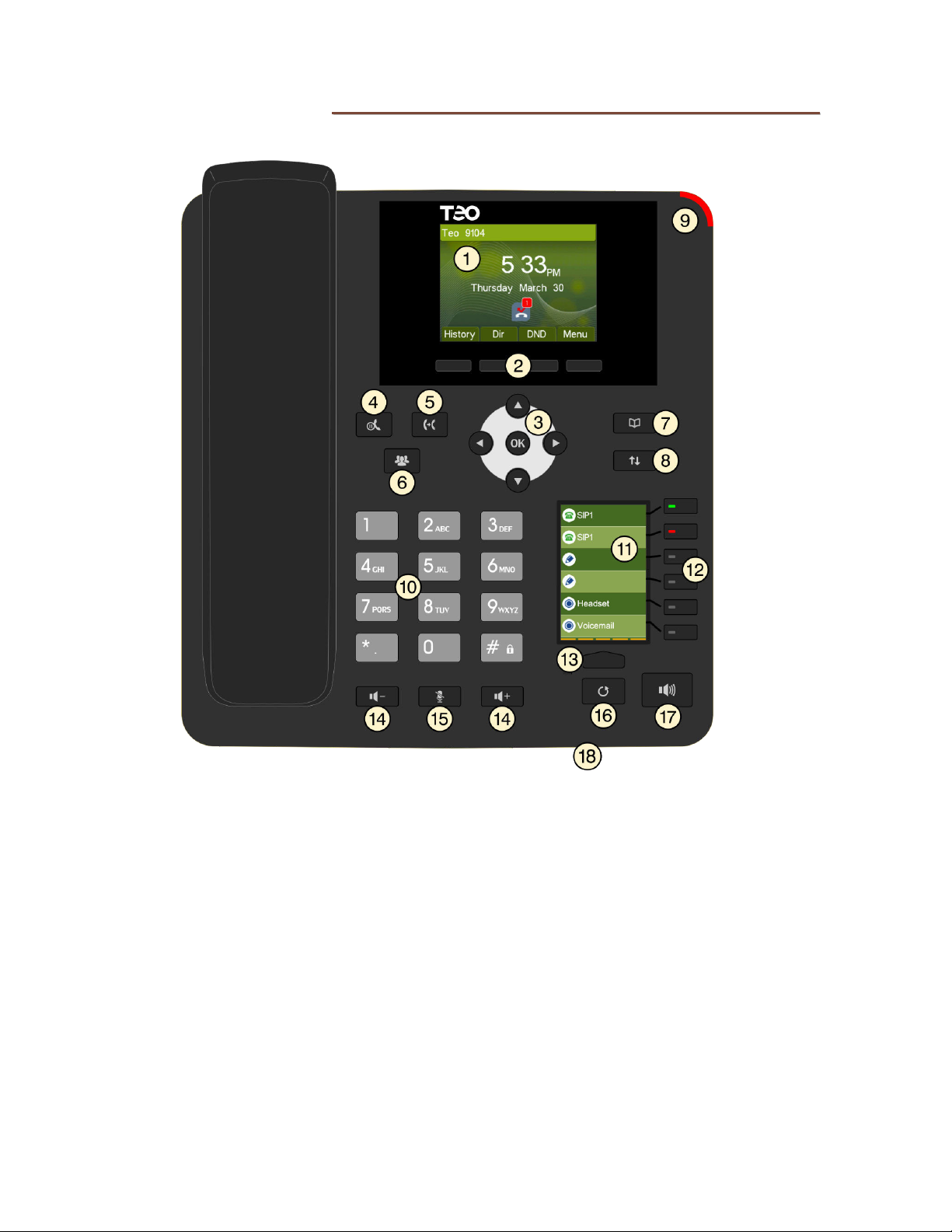
1) Main Display – color screen shows call progress, line states, missed calls, and other
information. Softkey options are shown above the four softkeys.
2) Softkeys – select the function displayed above the key on the bottom line of the display.
3) Navigation Keys – navigate within menus. The
any changes made, and returns to the previous menu options.
4) Hold Key – places a call on hold.
5) Transfer Key – places the current call on hold, and selects an idle line appearance for
transferring the call. A second press completes a transfer.
6) Conference Key – adds parties to a conference call.
7) Phonebook Key – shows the Phonebook, where you can store up to 500 contacts.
8) Call Log Key – shows the log of incoming, outgoing, and missed calls.
9) Message Waiting Indicator – a red indicator flashes when messages are waiting;
controlled by the network.
Page 6 13-280143 Rev. A
OK key exits the current menu, saves
Page 7

Introduction
10) Dial Pad – dials telephone numbers, and sends DTMF tones to external equipment such
as voice mail systems. The dial pad is also used for text and number entry.
11) Key Display – shows the functions assigned to six multifunction keys. Five selectable
pages of six keys are available for a total of up to 30 keys.
12) Multifunction Keys – select the functions shown in the Key Display. Keys can be
configured for Line Appearance, DSS/BLF, Speed Dial, Call Pickup, Voicemail, Headset,
Multicast Paging, and Lock.
13) Page Key – changes the page of multifunction keys that is shown in the Key Display. Up
to five pages of six keys are available.
14) Volume Keys – adjust the receiver/speaker volume when on a call; adjust the ringer
volume when on-hook.
15) Mute Key – mutes the microphone when using the speakerphone or handset/headset. A
mute icon is shown in the main display while mute is active.
16) Redial Key – press to access the Dialed Call Log, and then select a previously dialed call
to redial.
17) Speaker Key – activates the speakerphone.
18) Microphone – used for hands-free (speakerphone) calling; located on the front edge of
the phone.
13-280143 Rev. A Page 7
Page 8

Teo IP Phone 9104 Installation Instructions
Page 8 13-280143 Rev. A
Page 9
I
n
s
t
a
l
l
a
t
i
o
n
I
n
s
t
a
l
l
a
t
I
n
s
t
a
l
i
l
a
t
o
n
o
n
i
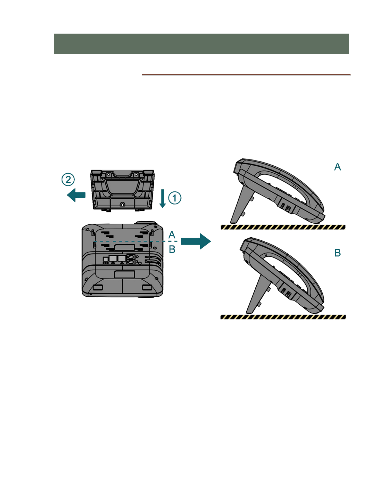
DDeesskkttoopp IInnssttaallllaattiioonn
The stand can be installed in two positions for desktop use. Select the position that
provides the best screen readability and easy control operation for the phone’s location.
Insert the four tabs on the short edge of the stand into one of the pairs of
inner slots on the phone. Use “A” slots for a low angle, or “B” slots for a high
angle as shown.
Press the stand toward the side of the phone until it locks into place.
13-280143 Rev. A Page 9
Page 10
Teo IP Phone 9104 Installation Instructions
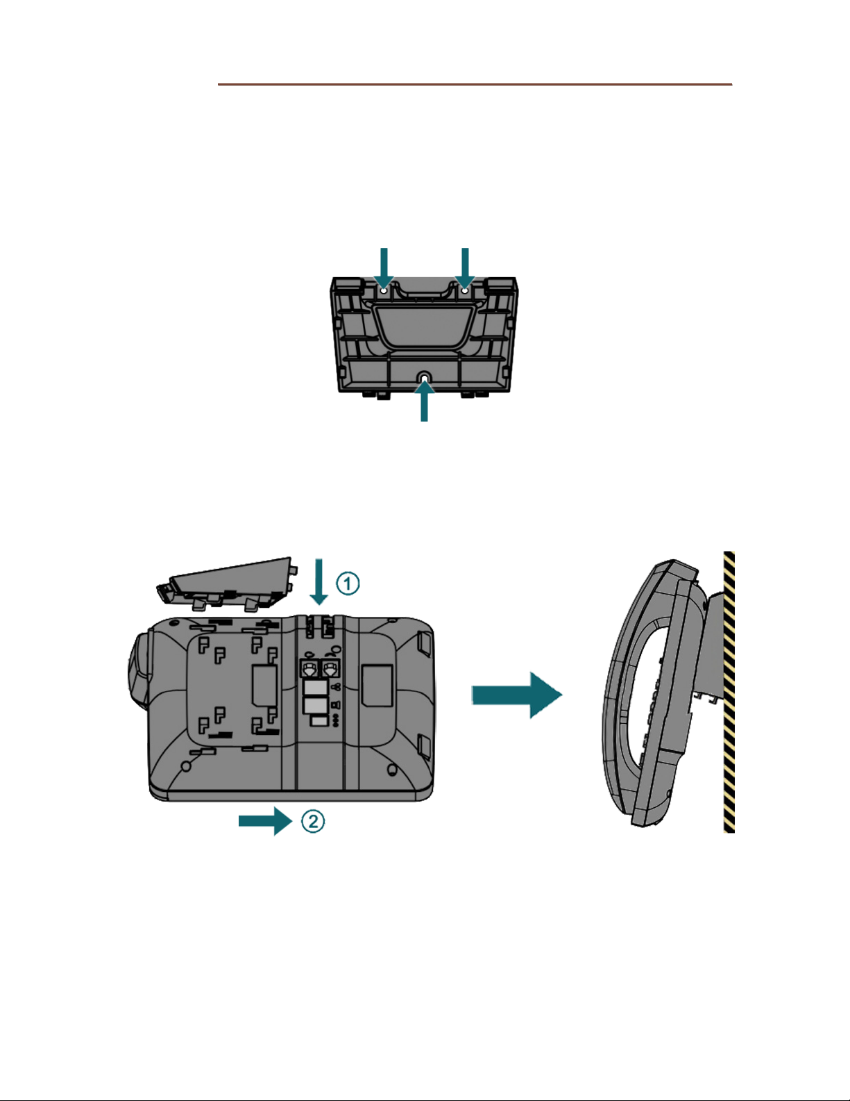
WWaallll MMoouunnttiinngg
To save space, you can directly hang the phone on a wall. You need three screws that will
fit the holes in the stand.
Note: Wall mounting screws are not supplied with the phone.
1. Mount the stand to the wall with the tabs facing out as shown, using three
screws suitable for the wall material.
2. Connect cables to the phone (page 11).
3. To attach the phone to the stand, insert the four tabs on the long edge of
the stand into the outer slots on the phone, and then
down until it locks into place.
press the phone
Page 10 13-280143 Rev. A
Page 11
Installation
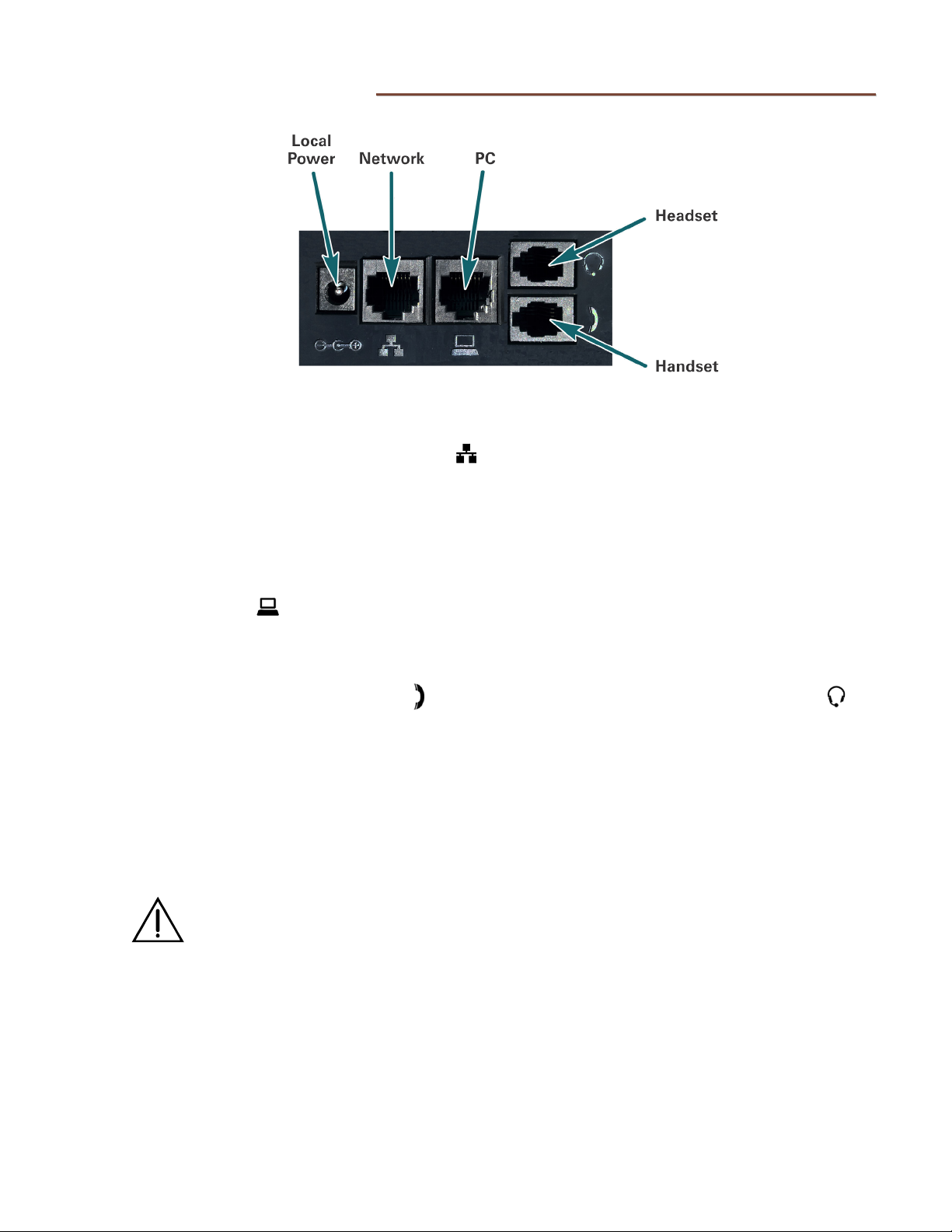
CCoonnnneeccttiinngg tthhee PPhhoonne
e
NNeettwwoorrkk CCoonnnneeccttiioonn
Connect the LAN switch to the phone’s LAN jack using a Category 5e or better cable. If
the network switch provides 802.3af Power over Ethernet (PoE), a local power supply
connection is not needed.
PPCC CCoonnnneeccttiioonn
If you want to use a PC on the same network connection, connect the PC network interface
to the phone’s PC
HHaannddsseett//HHeeaaddsseett
Plug the supplied handset into the Handset jack. Plug a compatible headset into the
Headset jack. Route the cords through the guides on the phone.
PPoowweerr
The IP Phone 9104 is compatible with IEEE 802.3af Power over Ethernet, utilizing either
power over spare cable pairs (midspan power source) or phantom power (powered
switch/hub port). The phone provides an 802.3af PD Class 2 indication to the power
sourcing equipment and requires a maximum of 5 watts of power.
jack using a Category 5e or better cable.
Power may also be provided by an optional local power supply.
WARNING: Use a Listed ITE "Limited Power Source, LPS or Class 2" power supply
rated 5 VDC, 1 A (
Connect power after all other connections are complete. If PoE is not provided,
plug the power supply barrel connector into the round power jack on the back of
the phone. Connect the power supply to a standard 100-240 VAC, 50-60 Hz power
outlet.
13-280143 Rev. A Page 11
Teo Model PWR8, Part Number 901058).
Page 12

Teo IP Phone 9104 Installation Instructions
Page 12 13-280143 Rev. A
Page 13

C
o
n
f
i
g
u
r
a
t
i
o
n
C
o
n
f
i
g
u
r
a
t
C
o
n
f
i
g
u
The IP Phone 9104 is typically configured by the Teo UCM (Unified Communications
Manager) Admin Portal. Using the Admin Portal, you can simplify the deployment of
multiple phones by creating reusable configuration templates.
Phone configuration is summarized in the following steps (details are in the following
sections):
1. (Optional) Configure DHCP Options.
2. Configure the phone in the UCM Admin Portal
• Add the device to a user extension. The default template will be used if a new
one is not added.
• Enter passwords and identifying label.
• Enter the UC server address and other network options as needed.
• Configure electronic hook switch, voice mode, and dialing mode options.
• Configure multifunction keys/
i
r
a
t
o
n
o
n
i
3. Complete setup at the phone.
• Reset to default configuration, if needed.
• Configure login credentials.
4. Wait for the phone to read its configuration information from the UC server, update
its settings, and complete registration with the system. This process can take up to
two minutes.
5. Verify phone registration by making a test call.
DDHHCCPP SSeerrvveerr CCoonnffiigguurraattiioonn
AAuuttoommaattiicc IIPP CCoonnffiigguurraattiioonn ((DDHHCCPP))
DHCP (Dynamic Host Configuration Protocol) assigns IP addresses to telephones, and can
provide other information to the phones, such as update server address. When using
DHCP, phones do not need to be configured with static IP addresses.
The DHCP server can supply:
• Phone IP Address
• Phone Subnet Mask
• Domain Name
• Default Gateway IP Address (Router)
• DNS Server(s) IP Address(es)
• NTP Server IP Address
• Update Server IP Address (Boot Server Host Name)
Settings not supplied by DHCP must be entered locally at the phone, or in a configuration
file which is supplied to the phone via the Teo UC update server.
13-280143 Rev. A Page 13
Page 14

Teo IP Phone 9104 Installation Instructions
DDHHCCPP SSeerrvveerr AAvvaaiillaabbllee OOppttiioonnss
The DHCP server requires a scope of IP addresses that can be assigned to the phones. The
scope must be configured with the router address, vendor-specific info, and the update
server address.
You can use an existing DHCP server for assigning IP addresses to the telephones, or add a
new server.
SSccooppee OOppttiioonnss
The following scope options are supported:
11 SSuubbnneett MMaasskk
Enter the network subnet mask for the phone IP address range.
33 DDeeffaauulltt GGaatteewwaayy
Enter the default gateway IP address.
66 DDNNSS SSeerrvveerr
Enter the DNS server IP address.
4422 NNTTPP SSeerrvveerr
Enter the NTP server IP address.
6666 UUppddaattee SSeerrvveerr ((BBoooott SSeerrvveerr HHoosstt NNaammee))
Enter the Teo UC server IP address or fully qualified domain name with the protocol
prefix “
This option allows the IP Phone 9104 to automatically download a configuration file
from the Teo UC server at initialization.
Note: If DHCP Option 66 is not configured, the installer must manually enter the update server
teo://”. For example:
teo://10.10.10.1 0 (IP address) or
teo://myserver.c om (fully qualified domain name)
address at each phone (page 25).
Page 14 13-280143 Rev. A
Page 15

Configuration
PPhhoonnee CCoonnffiigguurraattiioonn iinn TTeeoo UUCCMM
1. Log on to the UCM as an administrator.
2. If the server handles multiple tenants, select a tenant from the popup list at the
lower left of the Dashboard screen.
3. Find or add the user that will be assigned to this phone
CONFIGURATION→USERS),
(
4. Click the DEVICE ASSSIGNMENTS tab.
5. From the SELECT A DEVICE TEMPLATE list, select a TEO 9104 template. Your
system may have custom templates in addition to the default template.
6. Click + ADD NEW DEVICE. The phone will be added to the list.
7. Select a device in the list to view or edit its options, as explained below.
DDeevviiccee IInnffoo aanndd PPaasssswwoorrddss
• LABEL – enter a name to identify the phone (optional).
• WEB PASSWORD – restricts access to the phone’s web-based configuration utility.
• INSTALL PIN – restricts access to Advanced Settings in the phone Menu.
13-280143 Rev. A Page 15
Page 16

Teo IP Phone 9104 Installation Instructions
• LOCK PASSWORD – password used to unlock the phone keyboard. The phone can
be locked by pressing and holding the # key or pressing the Lock multifunction key
(if provisioned). If LOCK PASSWORD is blank, the phone cannot be locked.
• MAC ADDRESS – this read-only field is blank when a device configuration is
created; it displays the MAC address of the phone after it is registered to the
extension. To move a phone to a different extension number, or to replace the
phone with a different one, you must first clear the registered MAC address by
clicking the
• USER AGENT – displays the SIP User Agent string, which includes the phone’s
revision level and MAC address.
X at the right of this field, and then click SAVE.
CCaallll aanndd IInntteerrffaaccee OOppttiioonnss
EElleeccttrroonniicc HHooookk SSwwiittcchh
When ELECTRONIC HOOK SWITCH is enabled, control signaling is provided on the
Headset interface to allow remote on-hook/off-hook control using a cordless headset.
Note: this feature is only compatible with Plantronics CS500 and Savi headsets and
requires an APD-80 adapter cable.
VVooiiccee MMooddee
• HANDSET – all operations that automatically go off-hook (such as Answer, speed
• HEADSET – automatic off-hook operations connect to the headset instead of the
dial or DSS) will connect to the speakerphone first. Ringing for incoming calls is
heard on the speaker.
speakerphone. Ringing for incoming calls is heard in the headset.
DDiiaalliinngg MMooddee
Dialing Mode controls automatic dialing.
• NORMAL – after the user has entered all digits, they must select Dial or press OK to
manually initiate dialing, or wait for the number of seconds set in TIMEOUT (SEC)
for automatic dialing.
• WARM DIAL – when the phone goes offhook, it will automatically dial the number in
the DESTINATION field after the number of seconds set in TIMEOUT (SEC). A user
can dial a different number before the timeout, canceling the automatic dialing.
• HOT DIAL – similar to WARM DIAL, but automatic dialing occurs immediately after
the phone goes offhook (no timeout).
Page 16 13-280143 Rev. A
Page 17

Configuration
NNeettwwoorrkk RReessoouurrcceess
Basic network information is typically provided by DHCP. SIP OPTIONS and SIP PROXY
SERVERS should be set explicitly via configuration download.
• IP Address – To set the IP address, subnet mask, and default gateway statically,
uncheck AUTOMATICALLY OBTAIN FROM DHCP. Leaving the fields blank will allow
static network information to be set locally at the phone, otherwise set values as
desired.
• DNS – To set the DNS server(s) statically, uncheck AUTOMATICALLY OBTAIN FROM
DHCP. Leaving the fields blank will allow static name server values to be set locally
at the phone, otherwise set values as desired.
• NTP – To set the NTP server(s) statically, uncheck AUTOMATICALLY OBTAIN FROM
DHCP. Leaving the field blank will allow the time server(s) to be set locally at the
phone, otherwise set value as desired.
• SYSLOG – To manually enable syslog, check ENABLE SYSLOG, and
SERVER ID and LOG LEVEL information.
• SIP OPTIONS – Change the TRANSPORT, NAT KEEP ALIVE, and NAT TIMER (SEC)
options if required by your network.
• SIP PROXY SERVERS – Select +PROXY and enter the Teo UC server IP address or
fully qualified domain name and port. If a backup server is installed, enter that
address below the primary server. If no proxy server is entered, the primary server
address is assumed to be the same as the Update Server address.
fill in the
13-280143 Rev. A Page 17
Page 18

Teo IP Phone 9104 Installation Instructions
MMuullttiiffuunnccttiioonn KKeeyy SSeettttiinnggss
Multifunction keys can be configured for a variety of functions described below. On the IP
Phone 9104, multifunction keys are shown on up to five screen pages with six keys per
page, for a total of 30 keys. a yellow bar at the bottom indicates the current page. Press the
Page key to select a different page; additional pages of keys are available if they have been
configured by the UCM.
You can allow the user to customize keys on a per-key basis locally on the phone. Keys that
are designated “SET AT PHONE” can be configured by the user at the phone, and will not
be overwritten by a configuration update.
Note: Do not set any keys to “SET AT PHONE” if the phone is configured for hot desking. This
feature overwrites all key assignments.
These key functions are available:
• LINE – first appearance of the primary line (extension number); LED indicator shows
line appearance status.
• ADDITIONAL LINE – additional appearances of the primary line; LED indicator
shows line appearance status. LINE and ADDITIONAL LINE keys for a call
appearance must be consecutive. The ADDITIONAL LINE option is available only if
the preceding key is configured for a line appearance.
• DSS/BLF (DIALOG) – initiates a call or picks up a ringing call to an assigned
extension; LED indicator shows the busy/ringing status of the assigned extension.
• SPEED DIAL – initiates a call to a preconfigured number.
• CALL PICKUP – initiates a directed call pickup.
• HEADSET – on-hook/off-hook control for the headset port.
• VOICEMAIL – initiates a call to the voicemail system; LED indicator shows message
waiting status.
• LOCK – locks the phone to prevent unauthorized use, except for emergency calls;
LED indicator is on red when phone is locked.
• MULTICAST – initiates a multicast page; LED indicator is on green when paging is
active.
• SET AT PHONE – key is configured locally at the phone by the user. A configuration
update will not override the user’s settings (not compatible with hot desking).
• Blank – key is unused and cleared at the phone.
Page 18 13-280143 Rev. A
Page 19

Configuration
MF Key
Page
MF Key
Number
UCM Key
MF Key
Page
MF Key
Number
UCM Key
CCoonnffiigguurriinngg MMuullttiiffuunnccttiioonn KKeeyyss
1. Click the MULTIFUNCTION KEY SETTINGS tab.
Key numbers in the
1
2
3
UCM correspond to phone keys as shown in this table:
1
2
1
2
1
2
19
20
3 3 3 21
4 4 4 22
5
6
1
2
3
5
6
7
8
9
4 10 4 28
4
5
5
6
1
2
3
23
24
25
26
27
5 11 5 29
6
12
1 13
2 14
3
4
5
6
15
16
17
18
6
30
13-280143 Rev. A Page 19
Page 20

Teo IP Phone 9104 Installation Instructions
2. Click a key in the list. Fields will be shown below the list, depending on the current
key type.
3. Select a key type from the TYPE list.
4. Enter a label in the LABEL field to identify the key.
5. Fill out any additional fields, such as SPEED DIAL number.
6. To delete a multifunction key (make it unused), hover over a key line in the table,
and then click the
When finished with phone configuration, click .
X that appears to the right of the line.
Page 20 13-280143 Rev. A
Page 21

Configuration
MMuullttiiccaasstt PPaaggiinngg
The IP Phone 9104 can be configured to respond to multicast pages and also to initiate
multicast pages with multifunction keys. IP addresses and ports associated with paging
zones must match between senders (multicast multifunction keys) and intended listeners. It
is not required for a phone to have listener zones configured for each multicast sender key;
a phone may page to zones it does not receive. Likewise, a phone can be configured to
listen to zones without having paging keys for those zones.
Proper operation of IP multicasting for paging requires that your local networking
equipment is configured to support the IGMP protocol, and multicasting. You should
consult with your IT staff to ensure that your network is properly configured to support
proper registration of multicast listeners using IGMP, and proper transmission of multicast
traffic across all subnets where phones will be connected. Ports used for other services
(such as SIP signaling) should not be selected for multicast paging.
CCoonnffiigguurriinngg MMuullttiiccaasstt LLiisstteenneerrss
1. Click the MULTICAST tab.
2. If ENABLE PRIORITY is selected, paging zones are prioritized (1 is the highest
priority) and will preempt lower priority zones. For example, a Priority 1 page will
preempt a Priority 2 page in progress. If ENABLE PRIORITY is not checked, all
paging zones have the same priority and will not preempt each other.
3. NORMAL CALL PRIORITY sets the priority of normal calls. For example, if a
normal (non-multicast) call is in progress with NORMAL CALL PRIORITY = 2 and a
Priority 1 multicast page is initiated, the phone will automatically place the call on
hold and respond to the multicast page. If a Priority 1 multicast page is in progress
when a normal call is placed to the phone, the incoming call will be immediately
13-280143 Rev. A Page 21
Page 22

Teo IP Phone 9104 Installation Instructions
redirected to voicemail and the page will not be interrupted. Likewise, if the same or
lower priority page (e.g. Priority 2) is initiated when the phone is on a normal call,
the normal call will not be interrupted. If the same or lower priority multicast page is
in progress when a normal call is placed to the phone, the phone will ring, allowing
the user a choice of remaining on the page or answering the incoming call. If
NORMAL CALL PRIORITY is set to DISABLED, normal calls are never preempted.
4. For each priority paging zone you wish to configure, click a row in the MULTICAST
LISTENERS table. The IP Phone 9104 can be configured to listen to up to 10
multicast zones.
5. Enter a paging zone NAME, IP ADDRESS and PORT. The recommended IP address
range is 239.0.0.2 to 239.255.255.254. Port numbers must be in the range of 1025 to
65535, and each zone should have a unique port number. IP addresses and port
numbers must be consistent between sending and listening devices.
6. To change a paging zone’s priority, click arrows in the rightmost column to move a
paging zone up or down in the list.
CCoonnffiigguurriinngg MMuullttiiccaasstt PPaaggiinngg KKeeyyss
1. Click the MULTIFUNCTION KEY SETTINGS tab.
2. Select an unused key.
3. Set the key TYPE to MULTICAST.
4. Enter the paging zone name in the LABEL field to identify the key.
5. Enter the appropriate IP ADDRESS and PORT for the paging zone. The
recommended IP address range is 239.0.0.2 to 239.255.255.254. Port number must
be in the range of 1025 to 65535, and each zone should have a unique port number.
IP addresses and port numbers must be consistent between sending and listening
devices.
When finished with phone configuration, click .
It may take a couple of minutes for the configuration to load into the phone.
Page 22 13-280143 Rev. A
Page 23

Configuration
CCoommpplleettiinngg CCoonnffiigguurraattiioonn aatt tthhee PPhhoonnee
After completing device setup in Teo UCM Admin Portal, perform the following steps at the
phone.
UUssiinngg MMeennuuss
Configuration items are accessed through the phone’s menus.
1. Select Menu to enter the Main Menu.
2. Scroll through the list with the Up and Down Navigation keys, or by selecting
Prev./Next.
Select Enter or press the OK key to select an item.
You can also press a dial pad key to jump to and select an item, e.g. 5 for
Phonebook.
Advanced Settings may be password protected; the default password is 123. Refer
to INSTALL PIN (page15).
3. If a double-headed arrow is shown next to an item, you can change the value with
the Left and Right Navigation keys, then select Ok or Save to retain the new setting.
4. Select Exit to return to the previous screen.
13-280143 Rev. A Page 23
Page 24

Teo IP Phone 9104 Installation Instructions
PPhhoonnee CCoonnffiigguurraattiioonn wwiitthh DDHHCCPP OOppttiioonn 6666 SSeerrvveerr AAddddrreessss
1. If this phone was configured on another extension, it must be removed from Teo
UCM and reset to factory defaults (page 26).
2. Within a minute after the phone initializes following power-up or reboot, the Auto
Provision message will appear:
3. Select View, and then enter the authentication username and password.
User is the extension number@tenant domain (e.g. 1000@teo) for multitenant
systems, or just the extension number (e.g. 1000) for single tenant systems.
Passwd is the SIP password assigned to the extension.
4. Select Start.
5. The phone will read its configuration information from the UC server, update its
settings, and complete registration with the system
6. Verify phone registration by making a test call.
Page 24 13-280143 Rev. A
Page 25

Configuration
PPhhoonnee CCoonnffiigguurraattiioonn wwiitthh SSttaattiicc SSeerrvveerr AAddddrreessss
Perform the following steps if your server does not have Option 66 configured with the Teo
Update Server address. You will need to set the appropriate server address and login
credentials in the phone menu to enable auto provisioning.
1. If this phone was configured on another extension, it must be removed from Teo
UCM and reset to factory defaults (page 26).
2. Select Static Provisioning Server.
(Main Menu → Settings → Advanced Settings → Maintenance → Auto Provision →
Static Provisioning Server).
Advanced Settings may be password protected; the default password is 123. Refer
to INSTALL PIN (page15).
3. Press the Up or Down Navigation key until Server is shown.
4. Enter the server address or fully qualified domain name with the dial pad.
5. Press the Down Navigation key to display User.
6. Enter extension number@tenant domain (e.g. 1000@teo) for multitenant systems,
or just the extension number (e.g. 1000) for single tenant systems.
7. Press the Down Navigation key to display Password.
8. Enter the SIP password assigned to the extension.
9. Select Save to save Static Provisioning parameters.
10. From the main menu, select Reboot System.
(Main Menu → Reboot System)
11. After the phone has restarted, the provisioning process will start within 30 seconds.
The phone will read its configuration information from the UC server, update its
settings, and complete registration with the system
12. Verify phone registration by making a test call.
13-280143 Rev. A Page 25
Page 26

Teo IP Phone 9104 Installation Instructions
RReesseett ttoo DDeeffaauulltt CCoonnffiigguurraattiioonn
Use this procedure to reset a phone to the factory default configuration.
1. If this phone has been configured on another extension in the Teo UCM, remove the phone
from the extension’s Device Assignments list. Hover the pointer over the device name and
click the
Check the MAC address to make sure that the correct device is removed. The phone’s MAC
address is printed on a label attached to the bottom of the phone.
2.
At the phone, select Reset to Default.
(Main Menu → Settings → Advanced Settings → Reset to Default)
X that appears at the right of the list.
Advanced Settings may be password protected; the default password is 123. Refer
to INSTALL PIN (page15).
3. Select Yes to continue.
The reset process will take about one minute.
Page 26 13-280143 Rev. A
Page 27

A
p
p
e
n
d
i
A
p
p
A
M
M
M
e
p
p
e
e
n
u
e
n
u
e
n
u
1 Status (view only)
1 Mode (IP address mode)
2 IP
3 Software (version)
4 WEB Portal (QR code for phone web portal)
5 More…
x
n
d
i
x
n
d
i
T
r
e
T
r
T
r
(phone IP address)
1 Network
1 MAC
2 Mode
3 IP
4 Mask (subnet mask)
5 Gateway
6 DNS1
7 DNS2
2 Accounts
1 SIP1
2 SIP2
3 SIP3
4 SIP4
3 Phone
1 Model (model number)
2 Hardware (version)
3 Software
4 RAM (used / total memory)
5 ROM (used / total memory)
4 TR069
x
e
e
AA
A
e
e
e
(phone MAC address)
(IP address mode)
(phone IP address)
(remote management)
(version)
2 Features
1 Call Forward (forward incoming calls)
1 SIP1
1 Unconditional (all calls)
2 Busy (only when busy)
3 No Answer (only when call not answered)
2 SIP2
2 Auto Answer (answer incoming calls)
1 SIP1
2 SIP2
3 SIP3
4 SIP4
3 Auto Hangup
4 Call Waiting
5 DND
6 Blocking Anonymous Call
13-280143 Rev. A Page 27
(reject incoming calls, per line or all lines)
1 SIP1
(alert for incoming calls when busy)
(block calls without caller ID)
Page 28

Teo IP Phone 9104 Installation Instructions
2 SIP2
3 SIP3
4 SIP4
7 Ban Outgoing
8 Hotline
1 SIP1
2 SIP2
3 SIP3
4 SIP4
9 Dial Plan
10 Dial Peer
11 Intercom
12 Auto Redial
13 Call Completion (prompt to redial when called line is idle)
14 Ring From Handset (plays ringtone in handset)
15 Hide DTMF
16 Password Dial
17 Pre Dial
18 Call Logs (enable call logs)
19 Default Line (use a default line for outgoing calls)
20 Auto Switch Line
(prevent outgoing calls)
(auto dial number when going offhook)
(enable pressing # to dial)
(rules to simplify dialing)
(auto answer calls with Alert-Info SIP header)
(prompt to redial if busy or rejected)
(hide digits after password prefix)
(enable dialing before going offhook)
(automatically select default line)
3 Settings
1 Basic Settings
1 Keyboard
1 DSS Key Settings
2 Programmable Keys
3 Desktop Long Pressed
4 Softkey (idle screen softkey functions)
2 Screen Settings
3 Ring Settings
(configure multifunction keys)
1 DSS Key 1
2 DSS Key 2
⋮
30 DSS Key 30
(navigation key functions)
1 OK
2 Arrow Up
3 Arrow Down
4 Arrow Left
5 Arrow Right
(navigation key functions when held down)
1 OK
2 Arrow Up
3 Arrow Down
4 Arrow Left
5 Arrow Right
1 (softkey 1)
(softkey 2)
2
3
(softkey 3)
(softkey 4)
4
1 Energysaving (screen dimming timeout)
Page 28 13-280143 Rev. A
Page 29

Menu Tree
1 Ring Volume (default ring volume levels)
1 Headset Volume
2 Handsfree Volume
2 Ring Type (ringtones)
4 Voice Volume (default voice receive volume levels)
1 Handset Volume
2 Handsfree Volume
3 Headset Volume
5 Time & Date
6 Greeting Words
7 Language
2 Advanced Settings
1 Accounts
1 SIP1
1 Basic Settings (SIP server address)
2 Advanced Settings (domain realm)
3 Feature Code (custom codes to enable / disable features at server)
2 SIP2
3 SIP3
4 SIP4
2 Network
1 Network Settings
1 Connection Mode (IP address mode)
(set automatically or manually)
(text at top of idle screen)
(password protected)
1 Mode (enable sending feature codes to server)
2 DND
3 CFWD Unconditional
4 CFWD on Busy
5 CFWD on No Answer
6 Blocking Anonymous Call
2 Static IP Settings (static IP addresses and mask)
3 DHCP Settings
4 PPPoE Settings
2 QoS&VLAN
1 LLDP Settings
2 QoS
3 WAN VLAN
4 LAN VLAN
3 VPN (mode, server, credentials)
4 Web Setting
1 Web Server Type (protocol)
2 Web Authentication
3 Default WEB User
3 Security
1 Menu Password (password for Advanced Settings)
2 Keyboard Status
3 Keyboard Password
4 Maintenance
1 Auto Provision
1 DHCP Option
13-280143 Rev. A Page 29
(DHCP DNS)
(status and credentials)
(authentication type)
(user type)
(locks phone keys)
(password to unlock phone keys)
Page 30

Teo IP Phone 9104 Installation Instructions
2 SIP Plug and Play
3 Static Provisioning Server
2 TR069
1 Settings
2 Status
5 Reset to Default
(reset ALL settings to factory defaults)
4 Applications
1 SMS (view or send SMS text messages)
2 Memo
3 Voice Message
1 SIP1
2 SIP2
3 SIP3
4 SIP4
4 Ping
(verifies connectivity to a network device)
5 Phonebook
1 Contacts (manage contacts)
2 Groups
3 Blacklist
4 Cloud Phonebook
5 LDAP
6 Speed Dial
7 Broadsoft Directory
(manage groups of contacts)
(reject calls from contacts)
6 Call Logs
1 Local Call Logs (view call activity logs)
2 Broadsoft Call Logs
7 Agent
8 Reboot System (restart the phone, settings are retained)
Page 30 13-280143 Rev. A
Page 31

A
p
p
e
n
d
i
i
n
n
c
c
c
d
d
e
e
e
x
i
x
i
A
p
p
p
e
e
e
r
p
r
r
v
v
v
e
e
i
i
A
S
S
S
SSeerrvviiccee
The Teo IP Phone 9104 has no user-serviceable parts inside; repair must be done by Teo.
Prior to equipment removal, call Teo Customer Technical Support for assistance in
determining the source of the problem. This critical action can often prevent needless
removal of equipment and subsequent customer inconvenience.
x
a
a
a
BB
B
n
n
n
d
d
d
W
W
W
a
a
a
r
r
a
n
t
y
n
t
y
t
y
r
r
a
n
r
r
a
Teo
Technical Support Department
11609 49
Mukilteo, WA 98275-4255 USA
Teo is committed to meeting the product needs of our customers. Please write or call us
with any suggestions for improvement.
th
Place West
Phone: (425) 349-1000
(800) 524-0024
Fax: (425) 349-1010
E-mail: tech@teotech.com
: www.teotech.com
Web
13-280143 Rev. A Page 31
Page 32

Teo IP Phone 9104 Installation Instructions
TTeeoo PPrroodduucctt WWaarrrraannttyy
For a period of one year from date of dealer purchase, but not to exceed 16 months from
date of manufacture, Teo Technologies, Inc. (Teo) warrants its products to be free from
defects in material and workmanship under conditions of normal use and service. Teo
shall, at its option, repair or replace any defective product which, in its opinion, has not
been misused, damaged, or improperly installed.
Repair or replacement under this warranty will be performed at Teo's factory.
Authorization must be obtained from Teo prior to returning a product for repair. Freight
must be prepaid for all units returned to Teo. Units repaired under warranty will be
shipped UPS Ground (or equivalent), freight prepaid by Teo.
Products that are older than the warranty period, but less than 7 years old, or still
manufactured by Teo may be repaired at the factory for a flat rate charge. Repaired out-ofwarranty units are warranted for 90 days from the date of repair.
The repair or replacement of a product under this warranty represents the entire obligation
of Teo; Teo shall not be liable for any special or consequential damages resulting from or
caused by any defect, failure, incapacity or malfunction of any of its products.
The foregoing express warranty is in lieu of all other warranties, express or implied,
including but not limited to any implied warranty of merchantability, fitness, or
adequacy for any purpose or use, quality, productiveness or capacity; Teo, to the
extent permitted by law, hereby disclaims all such other warranties.
Page 32 13-280143 Rev. A
Page 33

A
p
p
e
n
d
i
A
p
p
p
p
p
p
p
e
e
e
e
e
c
c
c
A
S
S
S
n
i
i
n
i
x
d
i
x
d
i
f
i
c
f
i
c
f
i
c
x
a
a
a
CC
C
t
t
t
i
o
n
s
n
n
s
s
i
o
i
o
CCoonntteennttss ooff SShhiippppiinngg CCoonnttaaiinneerr
Telephone + Stand
Handset
Modular handset coil-cord
Ethernet cable
SSttaannddaarrddss CCoommpplliiaannccee
FCC Part 15
Hearing Aid Compatible
CE Listed
NNeettwwoorrkk CCoommppaattiibbiilliittyy
10/100/1000BaseT Ethernet
PPoowweerr RReeqquuiirreemmeennttss
Power over Ethernet: 802.3af Class 2
Optional Local Power: 5 VDC nominal @ 1 A max.
PPhhyyssiiccaall DDiimmeennssiioonnss
8.2” H x 7.7” W x 2.9” D
WWeeiigghhtt
1.75 lbs., including stand and handset
EEnnvviirroonnmmeennttaall
Operating Temperature: 32° to 104° F (0° to 40° C)
Humidity: 10% to 65% non-condensing
13-280143 Rev. A Page 33
Page 34

Teo IP Phone 9104 Installation Instructions
Page 34 13-280143 Rev. A
Page 35

A
p
p
e
n
d
i
A
p
p
p
e
e
e
p
g
g
g
e
e
u
u
u
A
R
R
R
n
n
l
l
x
d
i
x
d
i
x
a
t
o
a
t
o
l
a
t
o
DD
D
r
y
r
y
r
y
S
t
a
t
e
m
e
n
t
s
S
t
a
t
e
m
e
S
t
a
t
e
m
e
n
n
t
s
t
s
IImmppoorrttaanntt SSaaffeettyy IInnssttrruuccttiioonnss
1. Read the installation instructions before connecting the system to its power source.
2. Installation of equipment must not route interconnecting cables or external power supply sources
outdoors. This is defined as "Network Environment 0" by IEC TR 62101.
3. Never install network jacks in wet locations unless the jacks are specifically designed for wet locations.
4. Never touch uninsulated wires or terminals.
5. Do not connect this product to telephone network voltage (TNV) circuits. Some LAN and WAN ports both
use RJ-45 connectors. Use caution when connecting cables.
When using your telephone equipment, basic safety precautions should always be followed to reduce the risk
of fire, electric shock and injury to persons, including the following:
6. Read and understand all instructions.
7. Follow all warnings and instructions marked on the product.
8. Unplug all cables before cleaning. Do not use liquid or aerosol cleaners. Use a damp cloth for cleaning.
9. Do not use this product near water, for example, near a bathtub, wash bowl, kitchen sink, or laundry tub,
in a wet basement, or near a swimming pool.
10. Do not place this product on an unstable cart, stand, or table. The product may fall, causing serious
damage to the product.
11. This product should be operated only from the type of power source indicated on the marking label.
12. Do not allow anything to rest on the power cord. Do not locate this product where the cord will be
abused by persons walking on it.
13. Do not overload wall outlets and extension cords as this can result in the risk of fire or electric shock.
14. This product contains "No User-Serviceable Parts."
15. `Unplug this product from the wall outlet and refer servicing to qualified service personnel under the
following conditions:
A. When the power supply cord or plug is damaged or frayed.
B. If liquid has been spilled into the product.
C. If the product has been exposed to rain or water.
D. If the product does not operate normally by following the operating instructions. Adjust only those
controls that are covered by the operating instructions, because improper adjustment of other
controls may result in damage and will often require extensive work by a qualified technician to
restore the product to normal operation.
E. If the product has been dropped or the case has been damaged.
F. If the product exhibits a distinct change in performance.
SSAAVVEE TTHHEESSEE IINNSSTTRRUUCCTTIIOONNSS
13-280143 Rev. A Page 35
Page 36

Teo IP Phone 9104 Installation Instructions
FFCCCC RReeqquuiirreemmeennttss
The Teo IP Phone 9104 is hearing-aid compatible (HAC) per Section 68.316, FCC Rules and
Regulations.
This equipment has been tested and found to comply with the limits for a Class A digital device,
pursuant to Part 15 of the FCC Rules. These limits are designed to provide reasonable protection
against harmful interference when the equipment is operated in a commercial environment. This
equipment generates, uses, and can radiate radio frequency energy and, if not installed and used in
accordance with the instruction manual, may cause harmful interference to radio communications.
Operation of this equipment in a residential area is likely to cause harmful interference in which case
the user will be required to correct the interference at their own expense.
Page 36 13-280143 Rev. A
 Loading...