

Page 1
.Tone Commander Systems, Inc.
11609 49
Mukilteo, WA 98275-4255
(800) 524-0024 (425) 349-1000
www.tonecommander.com
th
Place West
Fax (425) 349-1010
8610 / 8620
ISDN Telephone
Installation
Instructions
13-280116 Rev. C
July 2008
Page 2

Tone Commander 8610/8620 Installation Instructions
Changes in this revision:
• Stand mounting instructions are clarified.
This manual applies to 8610/8620 software version 01.07.xx
© 2006, Tone Commander Systems, Inc. All rights reserved.
Printed in USA
Tone Commander is a registered trademark of Tone Commander Systems, Inc.
Page 2 13-280116 Rev. C
Page 3

Contents
Introduction ..................................................................................................................................................... 5
General Features ...................................................................................................................................... 5
Models/Options ......................................................................................................................................... 5
Controls and Indicators ............................................................................................................................. 7
Installation ....................................................................................................................................................... 9
Ordering ISDN Service .............................................................................................................................. 9
8610T/8620T Installation........................................................................................................................... 9
8610U/8620U Installation ........................................................................................................................ 12
Desktop Installation ................................................................................................................................. 13
Wall Mounting ......................................................................................................................................... 15
Configure the Set .................................................................................................................................... 17
Label the Set ........................................................................................................................................... 18
Installation Options ...................................................................................................................................... 19
Installation Options Menu ....................................................................................................................... 19
SPID Entry .............................................................................................................................................. 20
Parameter Download ........................................................................................................................... 20
Configuring Keys and Indicators ............................................................................................................. 21
Terminal Mode ........................................................................................................................................ 26
Installation Password .............................................................................................................................. 27
Reset to Factory Default Settings ........................................................................................................... 28
Voice Announce ...................................................................................................................................... 29
Administration Options ................................................................................................................................ 31
Administration Options Menu .................................................................................................................. 31
Local Inspect ........................................................................................................................................... 31
Version .................................................................................................................................................... 34
Test ......................................................................................................................................................... 35
Diagnostic Display ................................................................................................................................... 37
Restart ..................................................................................................................................................... 37
Viewing the Error and Download Logs .................................................................................................... 37
Troubleshooting ............................................................................................................................................ 39
Inoperable Telephone Recovery Procedures ......................................................................................... 39
Telephone Configuration Troubleshooting .............................................................................................. 40
Appendix A Ordering ISDN Service .......................................................................................................... 41
Recommended Button Assignments ....................................................................................................... 42
Appendix B Setup Menu Tree
Appendix C Warranty and Service ............................................................................................................ 47
Appendix D Specifications ........................................................................................................................ 48
Factory Default Settings .......................................................................................................................... 49
Appendix E UL/FCC Statements .............................................................................................................. 50
................................................................................................................... 43
13-280116 Rev. C Page 3
Page 4

Tone Commander 8610/8620 Installation Instructions
Page 4 13-280116 Rev. C
Page 5

Introduction
For operation instructions and user setup options, please refer
to the 8610/8620 User Guide, doc. #14-280195.
General Features
Tone Commander 8610 and 8620 ISDN Telephones are easy to use multiline terminals with advanced
automatic setup capabilities. S/T and U interface models are available with 10 or 20 call appearances. The
phones support a wide variety of ISDN platforms listed in Appendix D.
Features of the 8610 and 8620 include:
• AutoSPID and Parameter Download • Automatic Switch Type Detection
• Call Log • Message Waiting Indication
• Call Timer • Ringing Control for Shared Lines
• Last Number Redial • Flexible Ringing Options
• Speed Dial • Desktop or Wall Mounting
• Hot Key Dialing • Integrated Speakerphone
• Direct Station Select • Voice Announce
• Call Directory • Handset or Headset Operation
Models/Options
Several 8600 series ISDN telephone models are available. The models differ in the number of multifunction
keys provided and type of ISDN connection.
The S/T models require an external NT1 Network Termination, such as Tone Commander’s NT1U-223TC
(rack mount) or NT1B-300TC (standalone). Two S/T telephones can share a si ngle ISDN line in a multipoint arrangement.
_____________________________________________
______________________________________________
U models include a built-in NT1, allowing direct connection to the ISDN line. An additional S/T jack allows
another terminal device to be connected to the network through the built-in NT1.
Options include the 8030X Button Expansion Module, which adds 30 multifunction keys to any 8610 or
8620 phone, the 8001TA RS-232 Terminal Adapter for interfacing the phone with any TAPI-compliant
Windows application, the 8002TA Analog Port Terminal Adapter for interfacing with any standard analog
telephone device, and the 8003TA Terminal Adapter, which combines the features of the 8001TA and
8002TA. The 8030X Button Expansion Module can be combined with any of the terminal adapter options.
Basic
Model
8610T
8620T
8610U
8620U
13-280116 Rev. C Page 5
Multifunction Keys
10 (40 with 8030X) S/T
20 (50 with 8030X) S/T
10 (40 with 8030X) U
20 (50 with 8030X) U
ISDN
Connection
Page 6
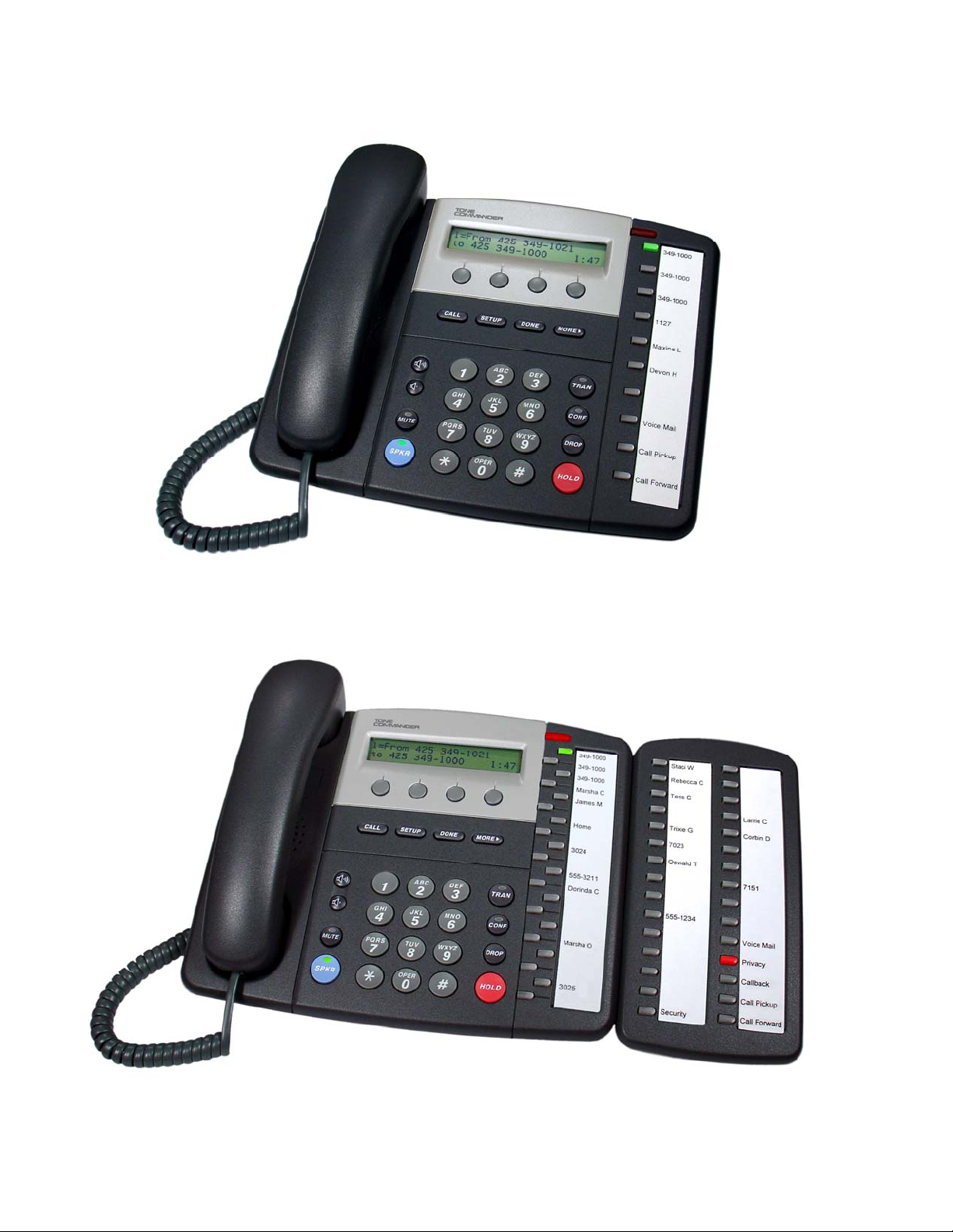
Tone Commander 8610/8620 Installation Instructions
8610
8620 with 8030X Button Expansion Module
Page 6 13-280116 Rev. C
Page 7
Introduction
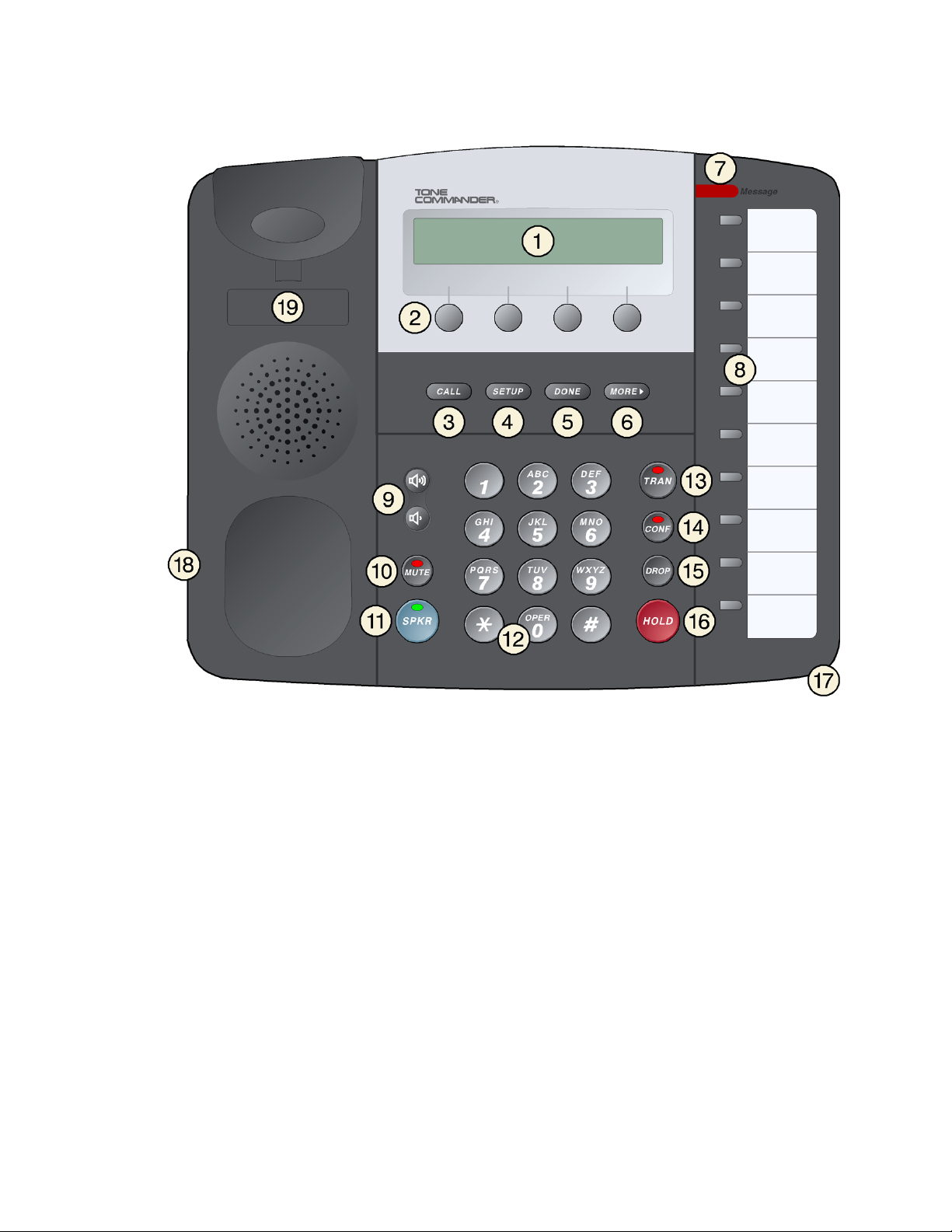
Controls and Indicators
_______________________________________
1) Display – shows the call state, caller ID, dialed digits, network call control messages, and elapsed time
during calls. When not on a call, the date, time of day, and softkey options are displayed.
The viewing is primarily set by selecting the high or low base mounting position (page 13). Viewing
angle display clarity can be altered by adjusting the display contrast.
2) Softkeys – select the function displayed above the key on the second line of the display.
CALL Key – selects the Call Directory, Call Log, and Call Identification Display modes.
3)
4)
SETUP Key – enters Setup Mode.
5)
DONE Key – exits the current menu, saves any changes made, and returns to the previous menu
options.
6)
MORE
7) Message Waiting Indicator – a bright red indicator is lit when messages are waiting, controlled by the
network.
Key – cycles through the menu option groups in Setup Mode.
4
13-280116 Rev. C Page 7
Page 8
Tone Commander 8610/8620 Installation Instructions
8) Multifunction Keys – select call appearances, activate network features, or dial personal speed dial
numbers. Red and green indicators on the keys show call appearance and feature status. The optional
8030X Button Expansion Module provides 30 additional multifunction keys.
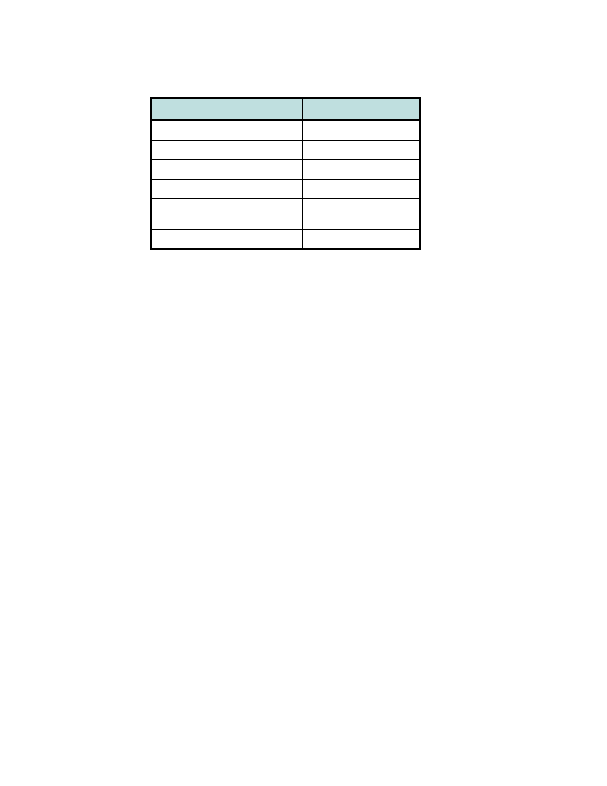
Call Appearance State Indication
Idle
Call Ringing
In Use by You
On Hold by You
In Use at Another Terminal
or an Activated Feature
On Hold at Another Terminal
Green – on steady
OFF
Green – flashing
Green – winking
Red – on steady
Red – winking
9) Volume Keys – adjust the receiver/speaker volume when on a call; adjust the ringer volume when onhook.
10)
MUTE Key – mutes the microphone when using the speakerphone or handset/headset. A red indicator
on the key is lit when mute is active.
11)
SPKR (Speaker) Key – activates the speakerphone. A green indicator on the key is lit when the
speakerphone is in use.
12) Dial Pad – dials telephone numbers, and sends DTMF tones to external equipment such a s voice mail
systems. The dial pad is also used for number entry during setup.
13)
TRAN (Transfer) Key – places the current call on hold, and selects an idle call appearance for
transferring the call. A second press completes a transfer.
14)
CONF (Conference) Key – adds other parties to a conference call.
15)
DROP Key – removes the last party added to a conference call, or disconnects you from a call and
returns new dial tone when not in conference mode.
16)
HOLD Key – places a call on hold.
17) Microphone – used for hands-free (speakerphone) calling; located in front of the Hold key on the
bottom of the telephone.
18) Handset/Headset Jack – a jack on the side of the telephone connects to the handset or a standard
headset.
19) Telephone Identification Label Area – indented area for a directory number label. Use ½” x 1¾”
adhesive labels (Avery 8167 / 5267 or equivalent).
Page 8 13-280116 Rev. C
Page 9
Installation
Ordering ISDN Service
ISDN ordering forms may be supplied by your service provider. You can also print forms using the PCbased Configuration Wizard. Please refer to Appendix A in this manual.
Consult your service provider to plan your service installation. Allow adequate time after cutover for testing
of all call appearances and programmed features. Ask your service provider for your SPID numbers, and
confirm the installation date.
8610T/8620T Installation
S/T models require an external NT1, such as the Tone Commander NT1U-223TC or NT1B-300TC.
________________________________________
_______________________________________
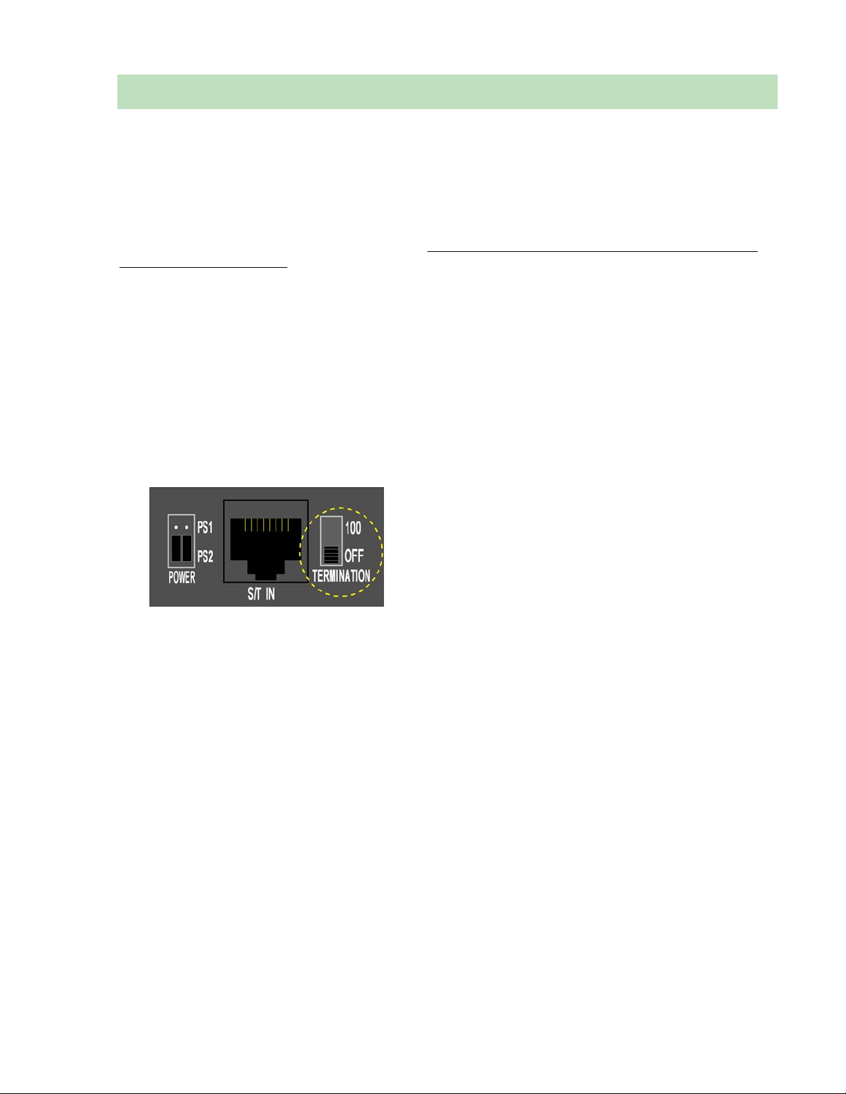
Set the Termination Switches on the Telephone and NT1
Set the termination switches on the bottom of the telephone and on the NT1 to match the termination
impedance to your premises wiring configuration. Several typical wiring configurations are shown below,
with the appropriate switch setting.
Available switch settings are OFF and 100 ohms.
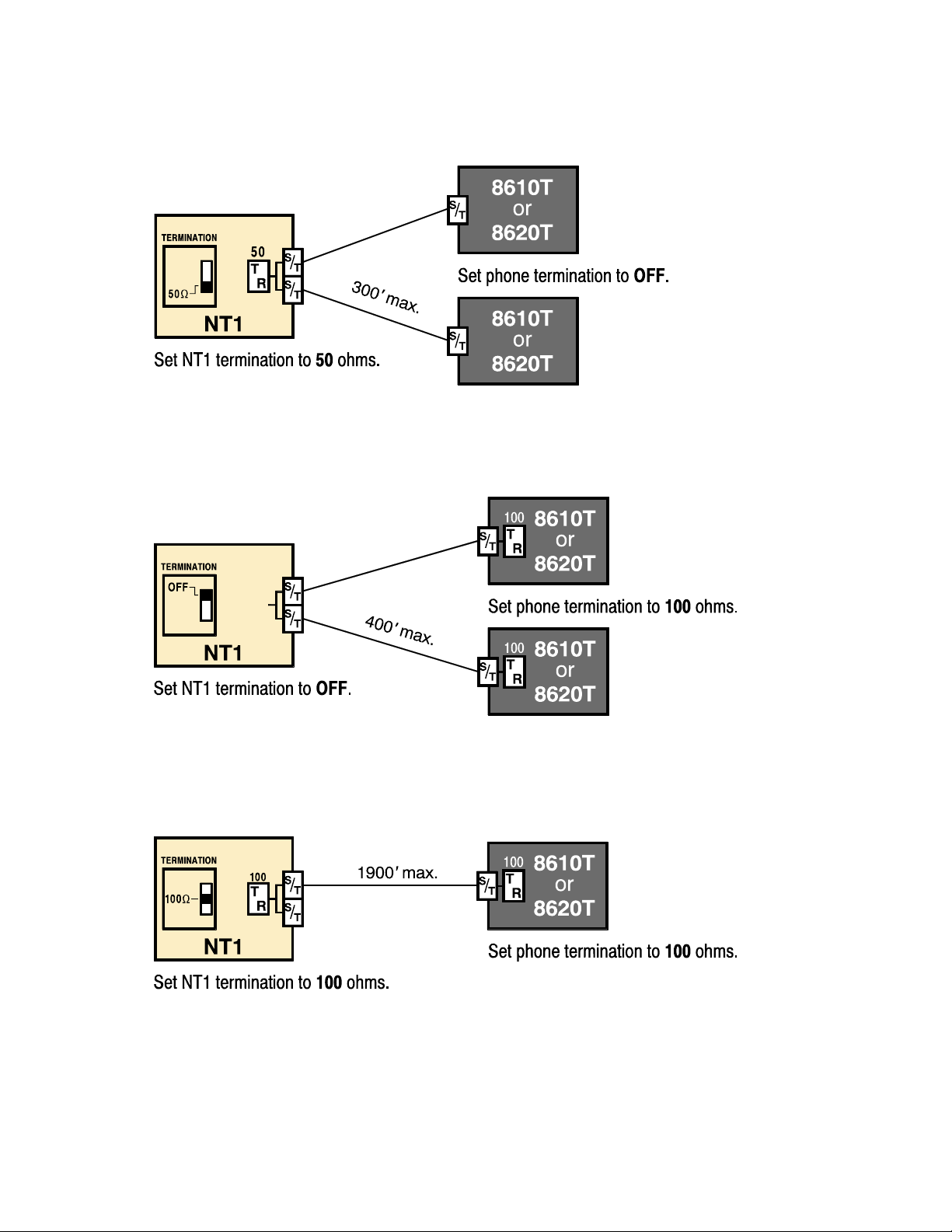
We recommend the use of Category 3 or better unshielded twisted pair cable with T568A or T568B
connector wiring. Distances shown are the maximums for 24-gauge cable, and may vary for other cable
types.
13-280116 Rev. C Page 9
Page 10
Tone Commander 8610/8620 Installation Instructions
Basic Multipoint:
(recommended for most applications)
Short Multipoint:
Extended Point-to-Point:
Page 10 13-280116 Rev. C
Page 11
Installation
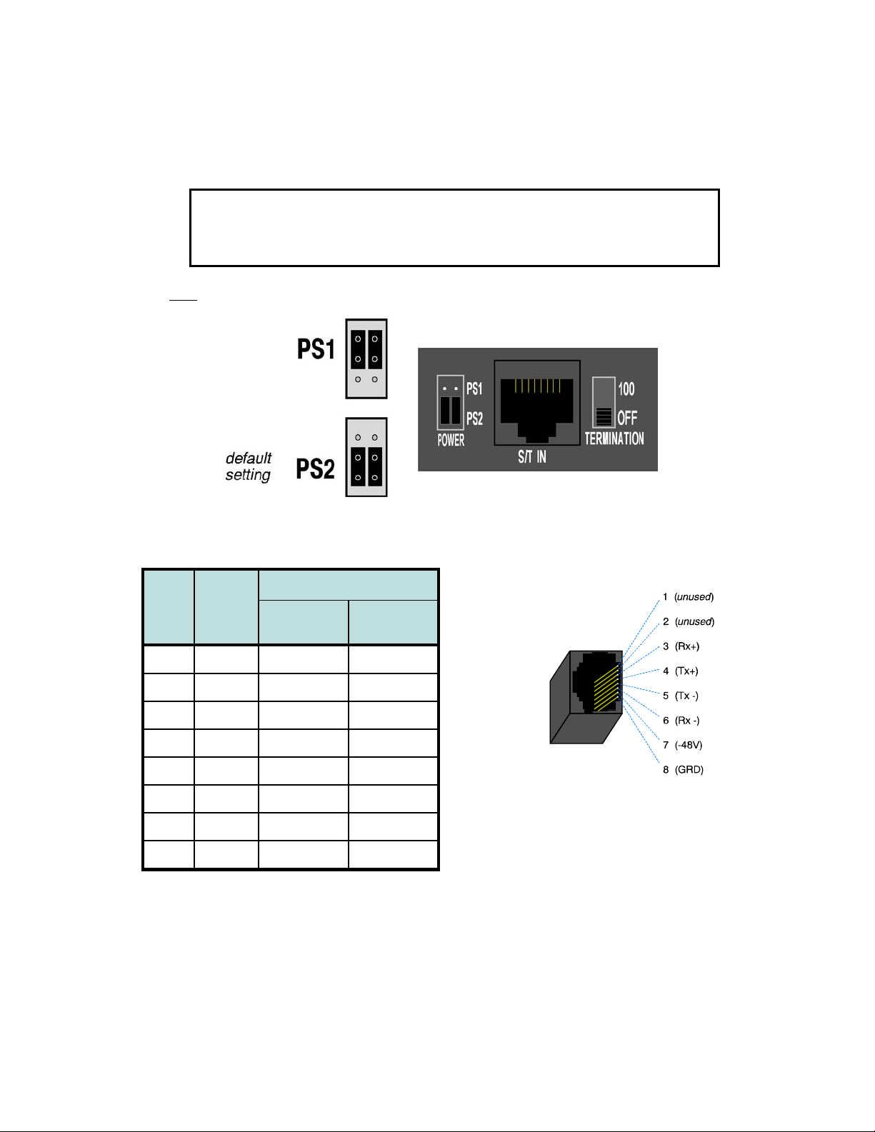
Line and Power Connections
Power for the telephone may be provided on PS1 (phantom power on the transmit and receive pairs from
the NT1) or PS2 (power on pins 7 and 8). Tone Commander manufactures NT1 products that supply power
on both PS1 and PS2. Contact Tone Commander or visit www.tonecommander.com for more
information.
WARNING: If a separate power supply is used to provide PS2 power to the
telephone, make sure that the output ground of the NT1 power supply and the
PS2 power supply are connected (with the correct polarity) to a common ground
reference point or electrical damage to the telephone may occur.
• Set both power jumpers to PS1 or PS2 as required. PS2 powering is used in most applications.
• Using an 8-conductor line cord, connect the S/T IN jack on the telephone to the TERMINAL jack on the
NT1. Route the cord under the guide tabs in the phone base.
Wire Color
Pin # Signal
T568 A
5 Tx- WHT-BLU WHT-BLU
4 Tx+ BLU BLU
1
unused
2
unused
3 Rx+ WHT-ORN WHT-GRN
6 Rx- ORN GRN
7 -48V WHT-BRN WHT-BRN
8 GRD BRN BRN
* T568 B jacks are recommended; they allow conventional statio n pair ordering when connecting to
S/T punchdown blocks on NT1 racks.
WHT-GRN WHT-ORN
GRN ORN
T568 B *
(AT&T 258A)
Modular Jack Pinout
Handset/Headset
• Plug the supplied handset or a compatible headset into the jack on the left side of the telephone.
13-280116 Rev. C Page 11
Page 12
Tone Commander 8610/8620 Installation Instructions
8610U/8620U Installation
U models include a built-in NT1. Optional external ISDN S/T Terminal Equipment may share the
telephone's ISDN line by connecting to the S/T jack on the telephone.
If you are not using external Terminal Equipment, no termination switch setting is required.
______________________________________
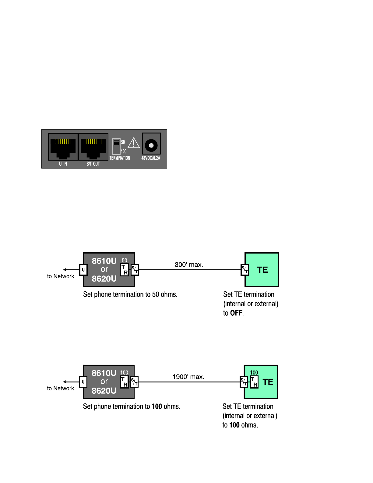
Set the Termination Switch on the Telephone
If external Terminal Equipment (TE) is connected, set the termination switch on the bottom of the telephone
to match the termination impedance to your premises wiring configuration. Two typical wiring configurations
for connecting external TE are shown below, with the appropriate switch settings.
Available switch settings are 50 and 100 ohms.
We recommend the use of Category 3 or better unshielded twisted pair cable with T568A or T568B
connector wiring. Distances shown are the maximums for 24-gauge cable, and may vary for other cable
types.
Basic Multipoint:
(recommended for most applications)
Extended Point-to-Point:
Page 12 13-280116 Rev. C
Page 13
Installation
Line and Power Connections
• Using an 8-conductor line cord, connect the U IN jack on the telephone to the line jack.
The 8610U and 8620U can be locally powered by a Tone Commander 901034 Desktop Power Supply.
This may be ordered with a phone as the –PWR1 Option.
• Plug the power supply barrel connector into the round jack on the back of the phone.
• When all other connections are completed, connect the power supply to a standard 120 VAC, 60 Hz
grounded power outlet.
Power can also be provided by an external -48 VDC source, such as a Tone Commander PS-50 ISDN
Power Supply, on pin 7 (-) and pin 8 (+) of the U IN jack.
Select only one powering method; DO NOT connect the local power supply and
power over the line cord simultaneously!
An additional terminal may be connected to the S/T OUT jack, which supplies PS1 and PS2 output power.
Handset/Headset
• Plug the supplied handset or a compatible headset into the jack on the left side of the telephone.
Desktop Installation
The stand can be installed in two positions for desktop use. Select the position that provides the best
screen readability and easy control operation for the phone’s location.
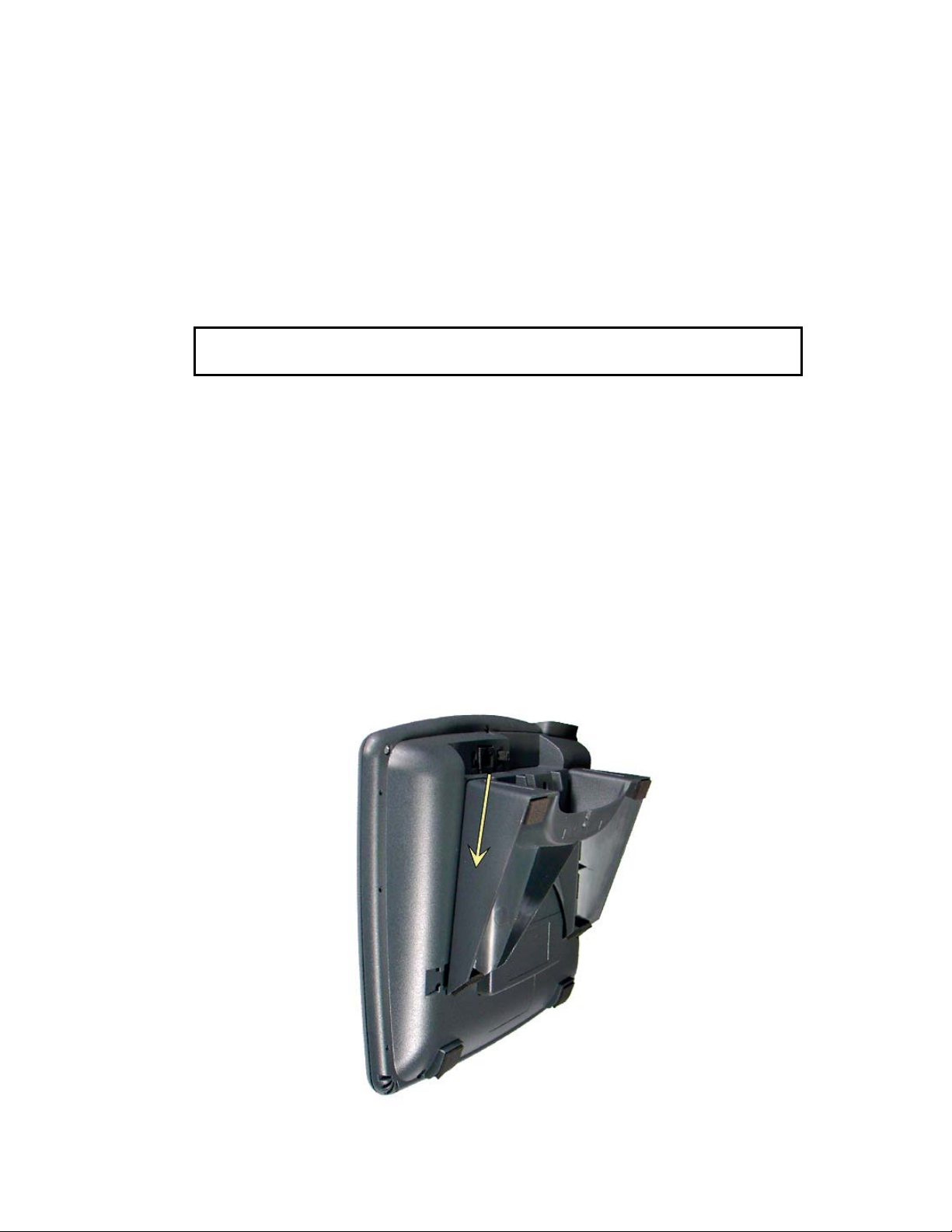
• If you need to remove the stand, press it down to disengage the snap tabs, and then lift off the stand.
The low desktop stand position is shown; the removal procedure is the same for high desktop and wall
mount positions.
__________________________________________
Stand Removal
13-280116 Rev. C Page 13
Page 14

Tone Commander 8610/8620 Installation Instructions
• Rotate the stand as needed; refer to the pictures below.
• To install the stand, insert the tabs on the telephone into the large openings in the stand’s upper sl ots,
and then press the stand toward the top of the telephone until it locks into place.
If you are installing an 8030X Button Expansion Module on the phone, use the double-width stand
included with the 8030X.
Low Desktop Position
High Desktop Position
Page 14 13-280116 Rev. C
Page 15
Installation
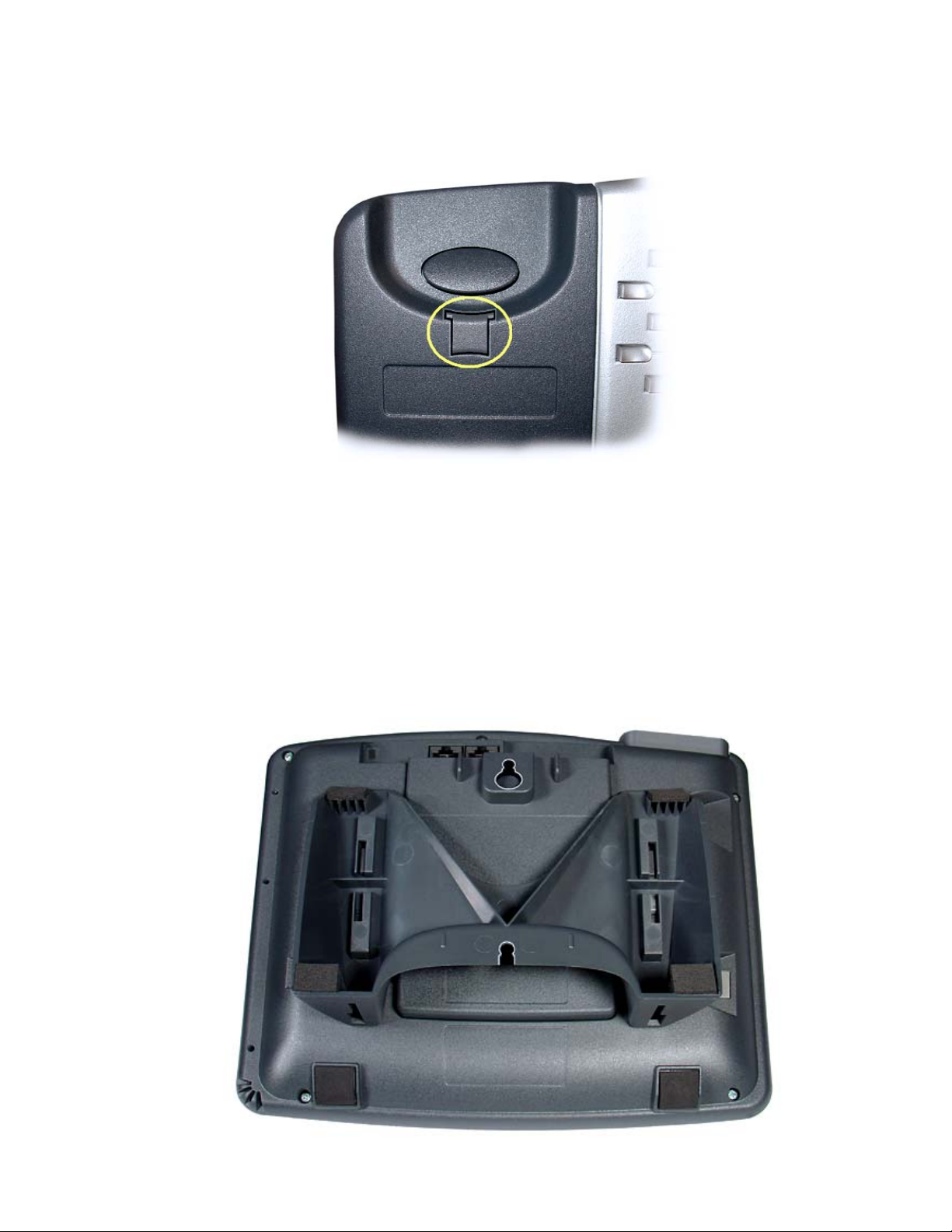
Handset Retainer Clip, Low Desktop Applications
For low desktop position use, the handset retainer clip should be installed in the default position, without
the tab protruding into the hookswitch area. Rotate the clip for high desktop applications – see page 16.
Wall Mounting
The phone stand and handset retainer clip must be rotated for wall mounting.
• Remove the stand from the phone base – see page 13.
• Rotate the stand as shown below.
• To install the stand, insert the tabs on the telephone into the large openings in the stand’s upper sl ots,
and then press the stand toward the top of the telephone until it locks into place.
_______________________________________________
13-280116 Rev. C Page 15
Page 16
Tone Commander 8610/8620 Installation Instructions
Attaching to a wall mount jack
• Plug an 8”, 8-pin line cord into the S/T IN jack (8610/8620T) or the U IN jack (8610U/8620U) on the
telephone. If you do not have one, you can obtain an 8” line cord by calling Tone Commander Technical
Support at (800) 524-0024.
• Hold the telephone next to the wall mount jack. Plug the line cord into the jack.
• Hang the telephone on the wall plate mounting studs. The top mounting stud fits into the keyhole slot in
the phone expansion cover or optional Terminal Adapter, and the bottom stud slides into the ‘U’-shaped
slot in the wedge base. Press down firmly to lock into place.
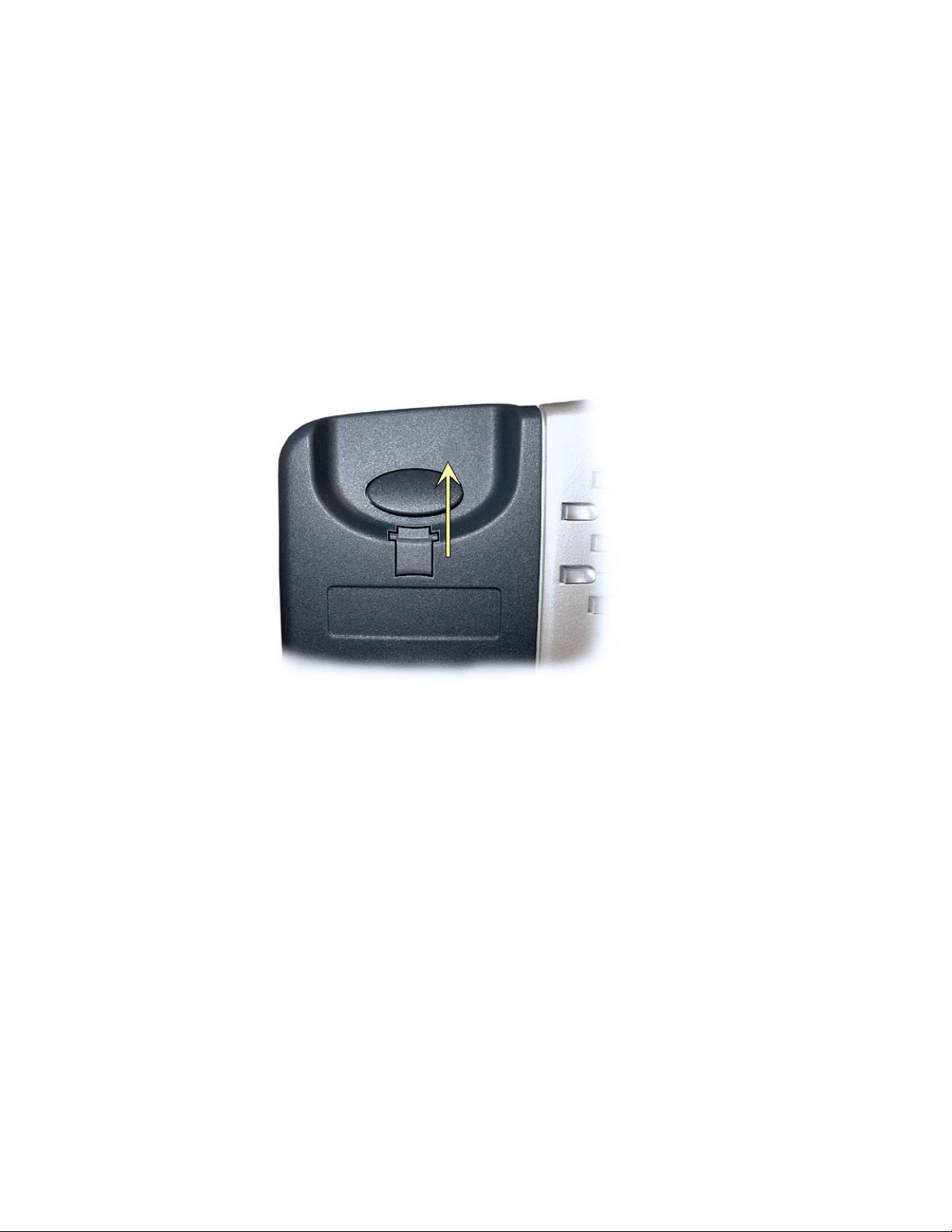
Handset Retainer Clip, Wall Mount or High Desktop Position Applications
Pull out the handset retainer clip as shown. Rotate the clip 180°, and then re-insert the clip. The tab should
protrude into the hookswitch area for wall mount or high desktop position use
Page 16 13-280116 Rev. C
Page 17

Installation
Configure the Set
ISDN configuration is performed automatically in many cases. The telephone set will detect the switch type,
set the SPID number, and download other setup parameters when these features are available from the
Telco central office.
You will be prompted for any required setup information that cannot be set automatically.
____________________________________________
Initialization
A self-test is performed upon power up. Press any key to begin initialization with the network. Unattended
initialization begins automatically after a short random time interval. This delay prevents multiple terminals
at a site from initializing simultaneously after a power outage.
The display will show progress while establishing the communication layers. When all three communication
layers are established, the TEI (Terminal Endpoint Identifier) and switch type will be shown for two
seconds.
L1:OK L2:OK TEI:123
L3:OK SWITCH=5ESS NI-X
SPID Entry
The SPID number will be assigned automatically if the network supports AutoSPID. If there is more than
one SPID available for your terminal, you will be prompted to select your primary telephone number.
If AutoSPID is not supported, you will be prompted to enter the phone’s primary telephone number, which
is used by the phone to generate a SPID number. Enter the number with the dial pad, and then press the
DONE key.
National ISDN – enter your full 10-digit
(including area code)
5ESS Custom ISDN – enter your 7-digit
Å
BKSP (backspace) deletes the previous digit.
telephone number
telephone number
ENTER PRIMARY PHONE #
999-555-1243 ←BKSP
Parameter Download (National ISDN only)
Parameter Download is a network feature that Identifies Call Appearance and Feature Activator keys that
are assigned to your line so that your phone may be configured automatically.
Note: Speed Dial, DSS keys, and other user preference settings are not
Download.
If Parameter Download is not supported, the following screen may appear momentarily, prom pting you to
manually configure the telephone at a later time (see page 20).
configured by Parameter
NO PARAMETER DOWNLOAD
PRESS SETUP TO CONFIGURE
Automatic Button Detection (5ESS Custom ISDN only)
Press each multifunction key. The phone will discover the key's network assignment. Keys that have no
network assignment may be used for speed dialing – please refer to page 24.
13-280116 Rev. C Page 17
Page 18

Tone Commander 8610/8620 Installation Instructions
Firmware Updates
Call Tone Commander technical support at (800) 524-0024 to get information on firmware updates.
Using Local Inspect to Verify Keys
Local Inspect allows you to identify the call appearance or feature assignment of each configured key,
directory number bearer capabilities, and the feature indicator assignment for the Message Waiting
Indicator. Please refer to page 31.
Label the Set
Label the multifunction keys with the telephone number, feature name, speed dial party name, or other
appropriate designation. A perforated label sheet is provided with the telephone.
The 8610/8620/8810 User Setup Program allows you to set up key labels, Speed Dial keys, Voice Mail
Menu keys, and the Call Directory using a Windows PC interface. The phone setup information can be read
from the phone, saved to disk, and loaded into an 8610, 8620, or 8810 telephone that is equipped with an
8001TA or 8003TA Terminal Adapter. The program will also print key labels for the 8030X Button
Expansion Module and 8610/8620 telephones. You can download this program from
www.tonecommander.com; please refer to Appendix A on page 41.
Install the key label overlays by inserting the tabs into the openings on the phone.
A space is provided beneath the handset for a directory number label. Use ½” x 1¾” adhesive labels
(Avery 8167 / 5267 or equivalent).
________________________________________________
Page 18 13-280116 Rev. C
Page 19

Installation Options
•
•
•
Options in this section are typically set at the time of installation. Many options can be set automatically by
the AutoSPID, Automatic Switch Detect, and Parameter Download features, if supported on the network.
The following options can be changed from the Installation Options menu:
• SPID
• Parameter Download
• Terminal Mode
• Keys and Indicators
Installation Options Menu
You can enter the Installation Options menu when the phone is idle.
Press the
SETUP key.
_____________________________________
Installation Password
Reset to Default Settings
Voice Announce
SETUP MENU
INSTL ADMIN USER POTS
Select INSTL.
INSTALLATION OPTIONS →
SPID PARAM KEYS MSG
When Æ appears in the top line of the display, you can press the
menu selections.
INSTALLATION OPTIONS →
MODE PASSWD RESET VA
MORE
key to see additional
4
Note: The POTS option is only available when the 8002TA or 8003TA Analog Port Terminal Adapter is
installed.
The PARAM and MODE options are only available with National ISDN.
A password may be set to prevent unauthorized entry into the Installation Options menu.
When prompted for a password, enter your password with the dial pad. Press the DONE
key after entering the password.
To change or remove the password, please refer to page 27.
13-280116 Rev. C Page 19
Page 20

Tone Commander 8610/8620 Installation Instructions
SPID Entry
A unique SPID (Service Profile IDentifier) is required for operation of the 8610/8620. If the network
supports AutoSPID, a SPID that is assigned to your ISDN line can be automatically selected. If National
ISDN generic SPID assignments are used by your service provider, your SPID will consist of your primary
telephone number followed by “0101” (e.g., 42534910000101). Contact your network service provider for
your telephone’s SPID.
From the Installation Options menu, select SPID.
(
__________________________________________________
SETUP → INSTL → SPID)
ID=42534910000101
←BKSP CLEAR
Using the dial pad, enter the SPID number supplied by your network service provider.
If you need to make corrections, select
CLEAR removes all digits, allowing you to start over.
When digits have been entered, press the
press the
SETUP key to exit Setup Mode.
Å
BKSP (backspace) to delete the previous digit.
DONE key to return to the Installation Options menu or
Parameter Download _________________________________________
(National ISDN only)
ISDN Parameter Download is an automated feature for configuring Call Appearance and Feature Activator
keys. If configured for auto download, a Parameter Download is executed when the phone initializes with a
new SPID, or when requested by the network, due to a line configuration change.
Note: Speed Dial and DSS keys are not
From the Installation Options menu, select PARAM.
(
SETUP → INSTL → PARAM)
configured by Parameter Download.
PARAMETER DOWNLOAD
START AUTO
Starting a Download
Select START to manually initiate a Parameter Download.
Enabling/Disabling Automatic Download
Select AUTO.
AUTO DOWNLOAD=ENABLED
ENABLE DISABLE
Select ENABLE or DISABLE.
Page 20 13-280116 Rev. C
Page 21

Installation Options
Configuring Keys and Indicators
If the network does not support Parameter Download, you can assign call appearances, directory numbers
and feature activators using this option.
From the Installation Options menu, select KEYS.
(
SETUP → INSTL → KEYS)
The status indicator for each key will indicate the current setting:
Green – Call Appearance or DSS
Red – Feature Activator
Off – Unused or Speed Dial
On the phone or Button Expansion Module, press the multifunction key to be programmed.
The selected key’s indicator will alternately flash red and green.
________________________________
12=CADN →
CADN FA DSS SPDIAL
12=CADN →
UNUSED
Select CA/DN (Call Appearance /Directory Number), FA (Feature Activator), DSS (Direct Station
Select), SPDIAL (Speed Dial), or UNUSED from the menu.
Programming procedures for each key type are described below.
Call Appearance / Directory Number Keys
These “line” keys are used to place and answer calls. If you have BASIC service or are connected to a
Nortel Meridian 1 Option Series PBX, each directory number key is assigned a unique directory number.
If you have CACH EKTS service, one directory number may be assigned to multiple Call Appearance
keys; multiple calls can be handled on one directory number.
Enter the assigned directory number with the dial pad.
For the Nortel Meridian 1 Option Series PBX, enter the same number of digits used in the PBX
dialing plan (2 to 7 digits).
If you need to make corrections while entering numbers, select
previous digit.
You can press the
DONE key to return to key selection.
Å
BKSP (backspace) to delete the
12=CADN# 5559876
←BKSP ORIG RESERV
13-280116 Rev. C Page 21
Page 22

Tone Commander 8610/8620 Installation Instructions
Automatic Call Appearance Selection
A call appearance is automatically selected when originating a new call, answering an incoming call, or
conferencing or transferring a call. Three configuration options determine how call appeara nces are
selected:
Call Preference (User option) – determines whether a new call is originated when you lift the han dset
or press the Spkr key. If set to NONE, you must manually press a Call Appearance key to originate a
call.
Originating DN – only call appearances with this option set to YES will be automatically selected for call
origination.
CA Reservation – within the group of originating DNs, call appearances set for NOT RESERVED are
selected first, followed by OUTGOING ONLY, followed by OUT/PRIORITY call appearances
(OUTGOING ONLY call appearances are selected first for conferencin g and transferring). Within each
subgroup, call appearances are selected in ascending order. INCOMING ONL Y call appearances are
never selected for an outgoing call. If an idle CA is not found, “SELECT AN IDLE LINE” is displayed.
To change the Originating DN assignment
Select ORIG.
Select YES or NO from the Originating DN menu.
Press the
To change call appearance reservation
Select RESERV.
Select the call appearance reservation for this CA/DN.
Press the
DONE key to return to the CA/DN menu.
:
OUT – Originate (outgoing calls) only.
IN – Terminate (incoming calls) only.
PRI – Outgoing or priority incoming calls only.
NOT – Not Reserved - default value for all keys.
DONE key to return to the CA/DN menu.
:
Page 22 13-280116 Rev. C
Page 23

Installation Options
Feature Activator Keys
Feature Activator keys must be configured to match network feature activator codes that have been
assigned to your line.
Using the dial pad, enter the feature activator code assigned by your network service provider.
If you need to make corrections while entering numbers, select
previous digit.
Å
BKSP (backspace) to delete the
10=NETWORK FA#59 (CALL)
←BKSP CALL
Select CALL if a call needs to be originated when the feature is activated. When enabled, (CALL)
will appear in the top line of the display as shown above.
With CALL enabled, the feature is always activated within the context of a call. Features that need
to originate a call include Call Forward (on Siemens EWSD), ICM intercom (on Nortel DMS-100),
and Call Pickup.
If the phone is on-hook when a Feature Activator key with CALL enabled is pressed, a new call
will be originated. If the phone is already off-hook when the feature key is pressed, the feature will
be activated within the context of the current call.
The CALL feature is not used with Lucent 5ESS Custom ISDN and Avaya Definity Custom ISDN.
Press the
Setup Mode.
DONE key twice to return to the key selection menu or press the SETUP key to exit
DSS Keys
DSS keys are a special type of Call Appearance/Directory Number keys that are programmed with speed
dial numbers to provide Direct Station Selection. When the call appearance is idle or busy, DSS keys act
like Speed Dial keys, to call a station. When ringing, DSS keys act like CA/DN keys, to answer a call. The
LED indicator on the key shows the status of the station’s call appearance (idle, ringing, hold, busy).
Shared call appearances for stations you wish to monitor must be configured on your ISDN line. You must
program the DSS number to dial the monitored station on your phone (even if Parameter Download is
provided).
If the Call Appearance/Directory Number is not shown in the top line of the display, you can enter
a reference directory number for the monitored station with the dial pad. This number is not
required for operation.
If you need to make corrections while entering numbers, select
previous digit.
Å
BKSP (backspace) to delete the
08=DSSDN# 5559876
←BKSP DSS#
Select DSS#.
1001
←BKSP CLEAR PAUSE
13-280116 Rev. C Page 23
Page 24

Tone Commander 8610/8620 Installation Instructions
Using the dial pad, enter the number you would dial to call the monitored station.
CLEAR removes all digits, allowing you to start over.
Press the
exit Setup Mode.
DONE key three times to return to the key selection menu or press the SETUP key to
Speed Dial Keys
Unused keys not assigned for call appearances or feature activators may be used as Speed Di al keys.
Dialing strings can include network feature activator codes, to simplify the use of feature s su ch as Directed
Call Pickup and Call Forwarding. Speed Dial keys may also be programmed from the User Options menu.
←BKSP FA PAUSE
The currently programmed dial string, if any, will be shown in the display.
Enter digits (24 maximum) with the dial pad.
After entering the first digit, pause, or feature activator, the FA softkey will be replaced by CLEAR.
5551234
←BKSP CLEAR PAUSE
If you need to make corrections while entering numbers, select
previous digit.
CLEAR removes all digits, allowing you to start over. A Speed Dial key will revert to 'Unused' if
saved with a cleared dial string.
“Smart” Pauses
Pauses are entered with the PAUSE softkey, and are shown in the display as a P character. The
first pause in a dial string will wait until the call is answered; additional pauses delay dialing for
one second. Enter multiple pauses to increase the delay time.
5551234P1P12
←BKSP CLEAR PAUSE
Å
BKSP (backspace) to delete the
Page 24 13-280116 Rev. C
Page 25

Installation Options
Feature Activator Codes
You can use Local Inspect (page 31) to view the codes assigned to Feature Activator keys on your
telephone, or consult with your network service provider for the required codes.
Feature Activator (FA) numbers are entered with the FA softkey, and are shown in the display as
an F character. F must be the first character in the dialing string; the two numeric digits
immediately following the F indicate the network feature activator code. The FA softkey is only
available when no digits have been entered.
←BKSP FA PAUSE
After entering F, the FA softkey will be replaced by CLEAR.
In the example below, the Speed Dial key sends feature code ‘57’ (Call Forward) followed by the
directory number ‘555-1234’.
F575551234
←BKSP CLEAR PAUSE
When digits have been entered, press the
press the SETUP key to exit Setup Mode.
DONE key twice to return to the key selection menu or
Message Waiting Indicator
The Message Waiting indicator must be configured to match the assigned network feature indicator code.
From the Installation Options menu, select MSG.
SETUP → INSTL → MSG)
(
MESSAGE=NETWORK FI#63
←BKSP
Using the dial pad, enter the feature indicator code assigned by your network service provider. In
most cases, this is set to 63.
If you need to make corrections while entering numbers, select
previous digit.
Press the
exit Setup Mode.
DONE key twice to return to the Installation Options menu or press the SETUP key to
Å
BKSP (backspace) to delete the
13-280116 Rev. C Page 25
Page 26

Tone Commander 8610/8620 Installation Instructions
Terminal Mode (National ISDN only) ______________________________
If the network does not support Parameter Download, you must manually select the terminal mode.
From the Installation Options menu, select MODE.
(
SETUP → INSTL → MORE
→ MODE)
4
TERMINAL MODE=CACH EKTS
CACH BASIC MERID1
Select the terminal mode based upon the type of service that was ordered from your network
service provider.
CACH – CACH EKTS (default).
BASIC – Voice or Basic EKTS.
MERID1 – Nortel Meridian 1 Option Series PBX.
In most cases, your phone service shoul d be configured for CACH EKTS.
Press the
Setup Mode.
DONE key to return to the Installation Options menu or press the SETUP key to exit
Page 26 13-280116 Rev. C
Page 27

Installation Options
Installation Password
You can set a password to prohibit unauthorized entry into the Installation Options menu.
If a password is currently set, the display will prompt you to enter your password prior to making changes.
From the Installation Options menu, select PASSWD.
SETUP → INSTL → MORE
(
_________________________________________
→ PASSWD)
4
INSTALLATION PASSWORD
SET CLEAR
Select SET.
NEW PASSWORD:
←BKSP
Enter a new 4 to 11 digit password with the dial pad.
If you need to change a password digit after entering it, select
previous digit.
Press the
DONE key.
ENTER AGAIN:
Å
BKSP (backspace) to delete the
←BKSP
Repeat the password when prompted to verify the new entry.
Press the
“PASSWORD SET” will be displayed to confirm the new password.
DONE key.
PASSWORD SET
Record your password for future reference.
Press the
Setup Mode.
DONE key to return to the Installation Options menu or press the SETUP key to exit
13-280116 Rev. C Page 27
Page 28

Tone Commander 8610/8620 Installation Instructions
Removing the Password
Select CLEAR.
“PASSWORD CLEARED” will be displayed to confirm that the password has been removed.
PASSWORD CLEARED
Press the
Mode.
DONE key to return to Installation Options menu or press the SETUP key to exit Setup
What to do if you lose your password
Contact your system administrator or call Tone Commander technical supp ort at (800) 524-0024 in the
event you misplace your password. You will need to report the serial number of your telephone to receive a
new password.
You can use the RESET option to remove all passwords. You must have access to the Installation Options
menu, which may be password protected, to use this feature. This option will clear all programmed
numbers and settings in your phone.
Reset to Factory Default Settings
Reset returns all settings to the factory defaults, and clears all speed dial numbers, logs, and passwords.
This option is useful when moving the telephone to a new user or location.
Default values are listed in the table on page 49.
From the Installation Options menu, select RESET.
SETUP → INSTL → MORE
(
→ RESET)
4
_______________________________
RESET ALL SETUP OPTIONS?
YES NO
Select YES to confirm the reset operation.
ALL SETTINGS CLEARED
PHONE WILL BE RESTARTED
INITIALIZING...
Press the
Mode. The phone will restart.
Page 28 13-280116 Rev. C
DONE key to return to Installation Options menu or press the SETUP key to exit Setup
Page 29

Installation Options
Voice Announce
This option allows certain incoming calls to be answered automatically by the speakerphone. Voice
Announce calls are restricted to calls on selected Call Appearance/Directory Number keys. In addition,
calls from specified directory numbers, and/or calls of a selected type determined by the ringing pattern can
be restricted. The microphone can be automatically disabled for announcing only, or enabled to allow twoway conversations. Voice Announce can be enabled or disabled by the user at any time.
From the Installation Options menu, select VA.
SETUP → INSTL
(
______________________________________________
→ MORE
VOICE ANNOUNCE OPTIONS
→ VA)
4
KEYS DNs ALERT MUTE
Selecting CA/DN Keys
Select KEYS to designate individual call appearances that will accept Voice Announce calls. Use
this setting to restrict Voice Announce calls to specific dialed directory numbers (e.g. non-listed
private numbers).
SELECT VA KEYS
GREEN=VA RED=AVAILABLE
All available CA/DN keys will light red, Voice Announce enabled keys will light green; all other
keys will be off. Press desired call appearance keys to enable or disable the Voice Announce
feature for selected keys.
Set all appearances of a directory number to the same Voice Announce setting.
Press the
Voice Announce configuration is not affected by Parameter Download, except when CA/DN key allocations
change. The default Voice Announce setting for new CA/DN keys identified in a download is disabled.
DONE key when all Voice Announce keys have been selected.
Selecting Incoming Directory Numbers
CA/DN keys must be configured for Voice Announce before selecting incoming DNs.
Select DNs to restrict Voice Announce calls to specific callers (or groups of callers). The Calling
DN templates are matched to the incoming caller ID to identify Voice Announce calls. You can
enter up to three Calling DN templates.
CALLING DN#1=9995551*
←BKSP CLEAR ALL
Select ALL if you want to accept all incoming calls.
To restrict Voice Announce calls to specific callers or groups, use CLEAR or
current entry, and then enter a combination of wildcards (
matches a single character) and numeric digits with the dial pad to allow individual callers or
blocks of callers.
13-280116 Rev. C Page 29
matches any group of characters, #
*
Å
BKSP to delete the
Page 30

Tone Commander 8610/8620 Installation Instructions
For example, 9995551* matches 999-555-1000 through 999-555-1999; 99955 510#0 matches
999-555-1010, 999-555-1020, etc. Non-numeric characters (such as hyphens) i n the incoming
caller ID are ignored. Up to 10 digits (including wild cards) may be programmed in each template.
Enter all digit positions as shown in the display for an incoming call; in most cases, this
will include the area code.
Press the
When all Calling DN templates have been entered, press the DONE key.
MORE
key to enter additional Calling DN templates.
4
Selecting Alerting Patterns
Use the Alert option to allow only specific types of incoming calls (e.g. internal, external, intercom, etc.).
CA/DN keys must be configured for Voice Announce before selecting alerting patterns.
Select ALERT to define a specific alerting pattern required to validate incoming Voice Announce
calls.
ALERTING=ANY →
ANY NORMAL DIST INTCOM
ALERTING=ANY →
PRI
ANY – Accept any type of alerting (default value)
NORMAL – normal alerting (pattern 0); typically used for internal calls.
DIST – distinctive alerting-intergroup (pattern 1); typically used for external calls
INTCOM – EKTS intercom (pattern 3); used for intercom calls
PRI – distinctive alerting-special/priority (pattern 2); used for designated priority calls
Press the
DONE key after selecting the alerting pattern.
Automatic Muting
Select MUTE.
Select ON to automatically mute the microphone during a Voice Announce call, or OFF to enable
two-way conversations.
Press the
DONE key after selecting the muting option.
AUTOMATIC MUTE=ON
ON OFF
Page 30 13-280116 Rev. C
Page 31

Administration Options
•
•
•
•
The following test and diagnostic options are available from the Administration Options menu:
• Local Inspect
• Hardware Version
• Software Version
• Serial Number
Administration Options Menu
You can enter from the Administration Options menu when the phone is idle or during an active call.
Press the
SETUP key.
__________________________________
Test Functions
Diagnostics
Terminal Restart
Error Log
SETUP MENU
INSTL ADMIN USER POTS
Select ADMIN.
ADMINISTRATION OPTIONS →
INSPCT VERS TEST DIAG
When Æ appears in the top line of the display, you can press the
menu selections.
MORE
key to see additional
4
ADMINISTRATION OPTIONS →
RESTART LOG
Note: The POTS option is only available when the 8002TA or 8003TA Analog Port Terminal Adapter is
installed.
Local Inspect
Local Inspect allows you to identify the call appearance/directory number or feature assignment of each
configured key, directory numbers, and the feature indicator assignment for the Message Waiting Indicator.
You can use Local Inspect after a Parameter Download to verify call appearance and feature assignments.
From the Administration Options menu, select INSPCT.
(
SETUP → ADMIN
________________________________________________
→ INSPCT)
LOCAL INSPECT
KEYS DNs MESSAGE
Select KEYS, DNs (Directory Numbers), or MESSAGE (Message Waiting Indicator). Each option
is described below.
13-280116 Rev. C Page 31
Page 32

Tone Commander 8610/8620 Installation Instructions
Keys
Select KEYS.
On the phone or Button Expansion Module, press the key that you want to inspect.
The key’s indicator will alternately flash red and green.
Displays will vary depending upon the key type, as shown below.
When you are finished inspecting keys, press the
press the SETUP key to exit Setup Mode.
Call Appearance/Directory Number Key
The display will show for the selected key:
• Key number, directory number
01=CADN# 999-555-1012 →
Press the
MORE
• Originate usage
• Call appearance reservation
key to view:
4
ORIGINATING DN? YES →
RESERVED=OUTPRIORITY IN
DSS Key
The display will show for the selected key:
• Key number, directory number
• DSS number
DONE key to return to the Local Inspect menu or
05=DSSDN# 999-555-4251→
4251
Press the
MORE
• Originate usage
• Call appearance reservation
key to view:
4
ORIGINATING DN? NO →
RESERVED=NOT RESERVED
Page 32 13-280116 Rev. C
Page 33

Installation Options
Feature Activator, Conference, Transfer, or Drop Key
The display will show the key number, network feature activator number, and service description
for the selected key.
07=NETWORK FA#56 (CALL)
Call Pickup
(CALL) is displayed if the feature has been locally programmed to originate a call when activated
(see page 23).
Speed Dial Key
The display will show the key number and programmed autodial string for the selected key.
08=SPEED DIAL
9995552341
Directory Numbers
Select DNs to view the list of directory numbers on this phone.
The first line on the display will show the directory number, and ‘ORIG’ if this is an originating DN.
DN#999-555-8952 ORIG →
Press the
Press the DONE key to return to the Local Inspect menu or press the SETUP key to exit Setup
Mode.
MORE
key to view additional directory numbers.
4
Message Waiting Indicator
Select MESSAGE.
The Message Waiting indicator will light.
The display will show the feature indicator number and the service description, if available. If the
service description on line 2 is blank after a National ISDN Parameter Downl oad, this feature has
not been provisioned on your line.
MESSAGE=NETWORK FI#63
Message Waiting
Press the
Mode.
13-280116 Rev. C Page 33
DONE key to return to the Local Inspect menu or press the SETUP key to exit Setup
Page 34

Tone Commander 8610/8620 Installation Instructions
O
Version
Use this option to view the telephone’s hardware version, software version, and serial number.
____________________________________________________
From the Administration Options menu, select VERS.
(
SETUP → ADMIN
→ VERS)
VERSION
SERIAL HW SW ADD-
Serial Number
Select SERIAL.
N
SERIAL# 90108307001
Hardware Version
Select H/W.
MODEL: 8620T
TOP:280001J PCB:280016C
Software Version
Select S/W.
SW VERSION: 01.07.20
Optional Equipment Version
Select ADD-ON to display installed options.
ADD-ON VERSION
8030X 8003TA
Select the add-on model to view its software version.
MODEL:8030X BUTTON EXPAN
VERSION: 05.01.01
Press the
Setup Mode.
Page 34 13-280116 Rev. C
DONE key to return to the Administration Options menu or press the SETUP key to exit
Page 35

Installation Options
________________________________________________________
Test
Select this option to test the LCD display, LED indicators, and keys.
From the Administration Options menu, select TEST.
(
SETUP → ADMIN
→ TEST)
TERMINAL TEST
DISPLY KEYS 8030X
Display and LED Indicators
Select DISPLY.
LCD Display
Select LCD.
All pixels (picture elements, or dots) on the display should turn dark.
Press any key to return the display to normal operation.
LED Indicators
Select RED to turn on all red indicators, and turn all others off.
Select GREEN to turn on all green indicators, and turn all others off.
Select OFF to turn off all indicators, or wait 5 seconds for automatic off.
Press the
Mode.
DISPLAYLED TEST
LCD RED GREEN OFF
████████████████████████
████████████████████████
DONE key to return to the Terminal Test menu or press the SETUP key to exit Setup
13-280116 Rev. C Page 35
Page 36

Tone Commander 8610/8620 Installation Instructions
Keys
Select KEYS.
PRESS EACH KEY TO TEST
OR GO OFF-HOOK TO EXIT
Press each key on the telephone (not on the Button Expansion Module), including the dial pad
keys, one at a time.
A letter should appear in the display for each pressed key.
On 8610 models, 10 additional letters will appear after the first keypress, representing the 10
“missing” multifunction keys.
ABCDEFGHIJKLMNOPQRSTUVWX
abcdefghijklmnopqrstuvwx
If all keys are operational, the following display will be shown. Press any key to return to the
Terminal Test menu.
KEY TEST PASSED
PRESS ANY KEY TO EXIT
If any key fails, or to exit before testing all keys, go off-hook with the handset or unplug the phone.
8030X Button Expansion Module
This option tests the keys and LED indicators on a 8030X Button Expansion Module. It is only available if a
8030X is connected to the phone.
Select 8030X.
PRESS EACH KEY ON 8030X
PRESS DONE TO EXIT
Press each key on the 8030X, one at a time.
The key's LED indicator should flash alternately red and green, and a number should appear in
the display for each pressed key.
123456789012345678901234
567890
After all keys have been tested, press any key to exit the test.
You can also exit the test at any time by pressing the
menu or press the
SETUP key to exit Setup Mode.
DONE key to return to the Terminal Test
Page 36 13-280116 Rev. C
Page 37

Installation Options
Diagnostic Display
From the Administration Options menu, select.
(
SETUP → ADMIN
The display will show the states of layers 1, 2, and 3, the Terminal Endpoint Identifier, and the
network switch type.
___________________________________________
→ DIAG)
L1:OK L2:OK TEI=64
L3:OK SWITCH=5ESS NI-X
Press the
Setup Mode.
Restart
Select Restart to reset the phone. If you are on an active call you will be disconnected. The call log will be
cleared. No configuration parameters will be altered.
_____________________________________________________
From the Administration Options menu, select RESTART.
(
SETUP → ADMIN
DONE key to return to the Administration Options menu or press the SETUP key to exit
→ MORE
→ RESTART)
4
RESTARTCLEAR CALL LOG?
YES NO
Select YES to restart the phone.
Viewing the Error and Download Logs
From the Administration Options menu, select LOG.
SETUP → ADMIN
(
→ MORE
→ LOG)
4
VIEW LOG ENTRIES
ERROR PARAM CLEAR
Select ERROR to view the error log or PARAM (National ISDN only) to view the Parameter
Download log.
The most recent log entry will be shown.
Press the
Press the
Mode.
Clearing Logs
Select CLEAR to remove all entries from the error log.
MORE
DONE key to return to the View Log Entries menu or press the SETUP key to exit Setup
key to view previous entries.
4
___________________________
Press the
Setup Mode. The Parameter Download log is re-written each time a new downloa d is performed.
13-280116 Rev. C Page 37
DONE key to return to the Administration Options menu or press the SETUP key to exit
Page 38

Tone Commander 8610/8620 Installation Instructions
Page 38 13-280116 Rev. C
Page 39

Troubleshooting
Inoperable Telephone Recovery Procedures
If a telephone is unable to operate normally or remains locked-up in a particular state:
1. Press the
select RESTART, and then select YES. This will cause the telephone to attempt re-initialization with
the network. If full initialization is achieved, proceed to “Verify operation…”.
2. If the phone display is active, but the Setup Menu does not function, disconnect and reconnect the line
cord or local power supply to cycle power on the phone. If full initialization is achieved, proceed to
“Verify operation…”.
3. If the phone display is blank and there are no lit LEDs, for an 8610T or 8620T, verify connection to an
external NT1 and verify power connection to the NT1. For an 8610U or 8620U, verify connection to an
external power supply and make sure the line cord is plugged into the U IN jack on the phone. If power
is connected to the phone, but the display remains blank, replace the phone.
4. If the phone appears operational but full initialization is not achieved, determine which protocol layer is
not initializing by observing the startup diagnostic display.
Layer 1 (L1) does not initialize:
• For an 8610T or 8620T, locate the external NT1 device for the phone; verify connection between
the U (LINE) connector on the NT1 and the Telco ISDN line. For an 8610U or 8620U, verify
connection between the U IN jack on the phone and the Telco ISDN line.
• If the external NT1 indicates Terminal Error, verify connection and correct polarity of all wire pairs
between the phone and the S/T (TERMINAL) connector on the NT1. On a multipoint line, verify
correct connections and polarity to the partner phone as well. Verify termination settings on both
phones and the NT1 (see page 9).
• For a standalone or single rack-mount NT1, press the NT1 reset button or cycle NT1 power by
temporarily disconnecting its stand-alone power supply or removing the NT1 from the rack.
CAUTION: If you remove an NT1U-223TC triple NT1 circuit card from the rack, it will disrupt service
to the other two NT1 circuits; plan accordingly.
• The network may take up to 3 minutes to synchronize L1 and L2 with the phone. If there is an
external NT1, verify correct line and terminal status indications on the NT1. Follow additional
troubleshooting procedures in your NT1 documentation.
• When Layer 1 is fully initialized, the display will indicate L1:OK
SETUP key; the Setup Menu should be displayed. Select ADMIN, press the MORE
4
key,
Layer 2 (L2) does not initialize within a few minutes:
• Repeat Step 1 (restart phone). If problem persists, contact your service provider.
• When Layer 2 is fully initialized, the display will indicate L2:OK and show the TEI number assigned
by the network.
Layer 3 (L3) does not initialize within one minute after L2:OK:
• Verify correct SPID number is programmed and that it is not already in use (on a multipoint line).
• Verify that your service provider has not changed SPID formats or area codes on your ISDN line.
(National ISDN SPID formats include the area code.)
• When Layer 3 is fully initialized, the display will temporarily show L3:OK and indicate the network
switch type before returning to the normal idle display.
Verify operation of the phone after full initialization:
1. Go off-hook on an idle line. The selected key should light green and you should hear dial tone.
2. Dial a valid directory number for a test call. Verify that the call is successfully completed.
13-280116 Rev. C Page 39
Page 40

Tone Commander 8610/8620 Installation Instructions
Telephone Configuration Troubleshooting
Symptom Check Fix
Inbound calls to a
specific line cause the
LED to flash, but there is
no audible ringing.
A specific line is selected
that is supposed to have
dial tone, but there isn’t
any.
All inbound calls appear
on CA1. Outbound calls
cannot be made.
Ringing calls are not
answered when going
off-hook.
“RINGER OFF
(VOL^ = ON)” is
displayed when idle.
SETUP → USER
RING → CONTROL
> Select line key
SETUP → INSTL
KEYS
> Select line key
SETUP → INSTL
MORE
SETUP → USER
MORE
→ MODE
4
→ PREF
4
→
→
→
→
Press the Vol5
key while not
call to enable the
ringer.
> ALWAYS
> CA/DN
Select CACH,
BASIC, or
MERID1 as
required by
service
provisioning.
> RING
on a
Using a specific headset,
the voice level to other
parties is not loud
enough.
“SELECT AN IDLE
LINE” is displayed when
going off-hook or
pressing the speaker
key.
SETUP → USER
MORE
HEAD → VOLUME
Originating DN and
Call Appearance
Reservation settings.
→ VOICE →
4
→
> XMT+ as many
times as required
See page 22.
Page 40 13-280116 Rev. C
Page 41

Appendix A
Ordering ISDN Service
Setup Wizard
The 8610/8620/8810 User Setup Program allows you to set up key labels, Speed Dial keys, the Call
Directory, and Voice Mail Menu keys using a Windows PC interface. The phone setup information can be
read from the phone, saved to disk, and loaded into any 8810, 8610, or 8620 telephone that is equipped
with an 8001TA or 8003TA Terminal Adapter. The program will also print key labels for the 8030X Button
Expansion Module and 8610/8620 telephones.
For ordering ISDN service, and printing key labels for other Tone Commander phone models, use the ISDN
Telephone Setup Wizard. You can download these programs, as well as label templates for Microsoft
Word, from Tone Commander’s Web site at www.tonecommander.com.
Ordering Manually
Your service provider may have their own process and forms for ordering ISDN service. Contact them for
instructions before you create your order.
Key Assignments
The 8610 and 8620 are compatible with all NIUF terminal packages and many other standard line
configurations. If Parameter Downloading is available, the phone will automatically assign Feature Activator
keys and codes to match almost any line configuration. Call appearances are always assigned in
ascending order, starting with button #1. Feature activators are assigned in descending order, starting with
button #10 on the 8610, #20 on the 8620, or the last button (#40 or #50) on the 8030X.
Use the table on the following page as a guide when assigning custom feature activators and indicators.
Where to Go for Help
If you need assistance ordering service, call Tone Commander Customer Technical Support at
(800) 524-0024.
13-280116 Rev. C Page 41
Page 42

Tone Commander 8610/8620 Installation Instructions
Recommended Button Assignments
Network
Button #
1 Call Appearance (PDN)
2 Call Appearances
3
.
.
.
.
.
.
58
59 Additional Feature Keys
60 Conference *
61 Transfer *
62 Drop *
63 Message Waiting Indicator
Assignment
* National ISDN only; DO NOT assign these keys for 5ESS Custom ISDN.
With Parameter Downloading, the phone will automatically remap feature activators (othe r tha n
Conference, Transfer, Drop, and Message Waiting) in descending order, starting with key 20 on the 8620
or key 10 on the 8610. For example, network feature key #59 will be assigned to key 10 on a 8610, #58 to
key 9, etc.
Page 42 13-280116 Rev. C
Page 43

Appendix B
Setup Menu Tree
INSTL (Installation Options)
SPID (Service Profile Identifier) ...................................... page 20
PARAM (Parameter Download – National ISDN only) .... page 20
START (Start Download)
AUTO (Automatic Download Enable/Disable)
KEYS .............................................................................. page 21
CA/DN (Call Appearance/Directory Number)
ORIG (Originating DN)
RESERV (Call Appearance Reservation)
OUT (Outgoing Only)
IN (Incoming Only)
PRI (Outgoing/Priority Incoming)
NOT (Not Reserved)
FA (Feature Activator)
CALL (Originate a Call – National ISDN only)
DSS (Direct Station Select)
DSS# (Enter/Edit DSS Dialing String)
SPDIAL (Speed Dial)
PAUSE (Dialing Pause)
FA (Feature Activator)
UNUSED
MSG (Message Waiting Indicator) ................................... page 25
MODE (Terminal Mode – National ISDN only) ............... page 26
CACH (Call Appearance Call Handling EKTS)
BASIC (Basic EKTS – National ISDN only)
MERID1 (Meridian 1 Option Series PBX)
PASSWD (Installation Password) .................................. page 27
SET
CLEAR
RESET (Reset to Default Settings) ................................ page 28
VA (Voice Announce) ..................................................... page 29
KEYS (CA/DN Keys that accept VA Calls)
DNs (Incoming Directory Numbers)
ALERT (Incoming Call Alerting Patterns)
MUTE (Automatic Microphone Muting)
13-280116 Rev. C Page 43
Page 44

Tone Commander 8610/8620 Installation Instructions
ADMIN (Administration Options)
INSPCT (Local Inspect) .................................................. page 31
KEYS (Call Appearance and Feature Activator Keys)
DNs (Directory Numbers)
MESSAGE (Message Waiting Indicator)
VERS (Version) .............................................................. page 34
SERIAL (Serial Number)
H/W (Hardware Versions)
S/W (Software Version)
[option model] (Optional Equipment Version,
if installed)
TEST ............................................................................... page 35
DISPLY (Display and Indicators)
LCD (Test LCD Display)
RED (Test Red Indicators)
GREEN (Test Green Indicators)
OFF (Turn All Indicators Off)
KEYS (Test Phone Keys)
8030X (Test 8030X Keys and Indicators, if installed)
DIAG (Diagnostic Display) .............................................. page 37
RESTART (Restart/Clear Call Log) ................................ page 37
LOG (Error & Parameter Download Logs) ...................... page 37
ERROR (Error Log)
PARAM (Parameter Download Log – Nat. ISDN only)
CLEAR (Clear Error Log)
Page 44 13-280116 Rev. C
Page 45

Setup Menu Tree
USER (User Options)
Options in this menu are described in the 8610/8620 User Guide.
CLOCK (Set Time and Date)
KEYS
CA/DN Keys:
DSS (Direct Station Select)
DSS# (Enter/Edit DSS Dialing String)
CLEAR (Remove Dialing String)
PAUSE (Dialing Pause)
CA/DN (No DSS)
Feature Activator Keys:
CALL (Originate a Call – National ISDN only)
Speed Dial Keys:
PAUSE (Dialing Pause)
FA (Feature Activator)
CLEAR (Remove Dialing String)
Unused Keys
DIR (Call Directory)
RING (Personal Ringing)
TONE (Ringing Tone)
ALL (All Keys use the same Ringing Tone)
OFFHK (Off-Hook Ringing)
NORMAL
SINGLE (Single Burst)
CONTROL (Ringing Control)
ALWAYS (Ring Immediately)
NEVER (Never Ring)
WAIT2 (Wait 2 Ring Cycles / 12 seconds)
WAIT3 (Wait 3 Ring Cycles / 18 seconds)
WAIT4 (Wait 4 Ring Cycles / 24 seconds)
WAIT5 (Wait 5 Ring Cycles / 30 seconds)
WAIT6 (Wait 6 Ring Cycles / 36 seconds)
WAIT7 (Wait 7 Ring Cycles / 42 seconds)
PREF (Off-hook Call Preference – National ISDN only)
RING (Answer Ringing Call)
IDLE (Select Idle Call Appearance)
NONE (Manual Call Appearance Selection)
VOICE (Voice Mode)
HAND (Handset)
HEAD (Headset)
VOLUME
RCV+/- (Receive Volume Up/Down)
XMT+/- (Transmit Volume Up/Down, Headset only)
DISPLY (Display Contrast)
+ (Increase Contrast)
- (Decrease Contrast)
PASSWD (Call Log Password)
SET, CLEAR
13-280116 Rev. C Page 45
Page 46

Tone Commander 8610/8620 Installation Instructions
POTS (8002TA/8003TA Analog POTS Port Options)
Options in this menu are described in the 8002TA/8003TA Analog Port Terminal Adapter
User Manual
RING (Ringing Control)
ALWAYS (Ring Immediately)
NEVER (Never Ring)
WAIT2 (Wait 2 Ring Cycles / 12 seconds)
WAIT3 (Wait 3 Ring Cycles / 18 seconds)
WAIT4 (Wait 4 Ring Cycles / 24 seconds)
WAIT5 (Wait 5 Ring Cycles / 30 seconds)
WAIT6 (Wait 6 Ring Cycles / 36 seconds)
WAIT7 (Wait 7 Ring Cycles / 42 seconds)
PRIV (POTS Line Privacy)
ON
OFF
CALLWT (Call Waiting Alert)
CALLID (Caller ID Display and Tone)
TONE (Call Waiting Tone only)
DISABLE
.
ORIG (POTS Originating Call Appearance)
Page 46 13-280116 Rev. C
Page 47

Appendix C
Warranty and Service
Tone Commander Product Warranty
For a period of one year from date of dealer purchase, but not to exceed 16 months from date of
manufacture, Tone Commander Systems, Inc. (Tone Commander) warrants its products to be free from
defects in material and workmanship under conditions of normal use and service. Tone Commander shall,
at its option, repair or replace any defective product which, in its opinion, has not been misused, damaged,
or improperly installed.
Repair or replacement under this warranty will be performed at Tone Commander's factory. Authorization
must be obtained from Tone Commander prior to returning a product for repair. Freight must be prepaid for
all units returned to Tone Commander. Units repaired under warranty will be shipped UPS Ground (or
equivalent), freight prepaid by Tone Commander.
Products that are older than the warranty period, but less than 7 years old, or still manufactured by Tone
Commander may be repaired at the factory for a flat rate charge. Repaired out-of-warranty units are
warranted for 90 days from the date of repair.
The repair or replacement of a product under this warranty represents the entire obligation of Tone
Commander; Tone Commander shall not be liable for any special or consequential damages resulting from
or caused by any defect, failure, incapacity or malfunction of any of its products.
The foregoing express warranty is in lieu of all other warranties, express or implied, including but
not limited to any implied warranty of merchantability, fitness, or adequacy for any purpose or use,
quality, productiveness or capacity; Tone Commander, to the extent permitted by law, hereby
disclaims all such other warranties.
13-280116 Rev. C Page 47
Page 48

Appendix D
Specifications
Contents of Shipping Container
Telephone + Stand
Handset
Modular line cord
Modular handset coil-cord
Label Sheet
Label Overlay
User Guide
Standards Compliance
ANSI T1.601-1992 and T1.605-1991
National ISDN, Lucent 5ESS Custom ISDN
FCC Part 15
FCC Part 68
Hearing Aid Compatible
FCC Part 68 Volume Control Requirements
UL, cUL Listed
Network Switch Compatibility
Lucent 5ESS – National and Custom ISDN
Avaya Definity, Multivantage, and Communication Manager PBX – National and Custom ISDN
Nortel DMS-100 – National ISDN
Nortel Meridian 1 Option Series PBX – National ISDN
Siemens EWSD – National ISDN
Lucent/AG Communication Systems GTD-5 – National ISDN
Power Requirements
PS1 (phantom) or PS2 (pins 7 and 8)
24 to 56.5 VDC @ 2 W max. per terminal (excluding wiring losses)
Physical Dimensions
9.6” W x 8.0” D x 3.5” H, excluding handset
Weight
2.3 lbs., including stand and handset
Environmental
Operating Temperature: 32° to 104° F (0° to 40° C)
Storage Temperature: 32° to 122° F (0° to 50° C)
Humidity: 5% to 95% non-condensing
13-280116 Rev. C Page 48
Page 49

Factory Default Settings
Specifications
Parameter
Auto Param. Download
CA Reservation
Call Log Password
Call Preference
Clock
Conference
Display Contrast
Drop
Handset Volume
Headset Volume
Install Menu Password
Message Waiting
Multifunction Keys 1-3
Default Value
(National ISDN)
Enabled
Not Reserved Not Reserved
None None
Ring (Network Controlled) *
Time of the last
error log entry
FA/FI=60
Level 5 Level 5
FA/FI=62
Level 3 Level 3
Level 3 Level 3
None None
FI=63 FI=63
CA/DN CA/DN
Default Value
(5ESS Custom ISDN)
N/A
Time of the last
error log entry
N/A
N/A
Multifunction Keys 4+
Off-hook Ring
Originating DN
Ringer Volume
Ringing Control
Ringing Tone
Speakerphone Volume
Terminal Mode
Transfer
Voice Announce Alert
Voice Announce DNs
Voice Announce Keys
Voice Announce Muting
Voice Mode
* fixed setting for 5ESS Custom ISDN
Unused Unused
Single Single
Yes, PDN Yes, Keys 1-3
Level 3 Level 3
Always Always
#5 (of 8) #5 (of 8)
Level 3 Level 3
CACH N/A
FA/FI=61
Any Any
All All
All Disabled All Disabled
On On
Handset Handset
N/A
13-280116 Rev. C Page 49
Page 50

Appendix E
UL/FCC Statements
Important Safety Instructions
1. Never install telephone wiring during a lightning storm.
2. Never install telephone jacks in wet locations unless the jack is specifically designed for wet locations.
3. Never touch uninsulated telephone wires or terminals unless the telephone line has been disconnected at the
network interface.
4. Use caution when installing or modifying telephone lines.
When using your telephone equipment, basic safety precautions should always be followed to reduce the risk of fire,
electric shock and injury to persons, including the following:
5. Read and understand all instructions.
6. Follow all warnings and instructions marked on the product.
7. Unplug the line cord before cleaning. Do not use liquid or aerosol cleaners. Use a damp cl oth for cleaning.
8. Do not use this product near water, for example, near a bathtub, wash bowl, kitchen sink, or laundry tub, in a wet
basement, or near a swimming pool.
9. Do not place this product on an unstable cart, stand, or table. The product may fall, causing serious damage to the
product.
10. This product should be operated only from the type of power source indicated on the marking label. If you are not
sure of the type of power supply to your home, consult your dealer or local power company.
11. Do not allow anything to rest on the power cord. Do not locate this product where the cord will be abused by
persons walking on it.
12. Do not overload wall outlets and extension cords as this can result in the risk of fire or electric shock.
13. Never push objects of any kind into this product through any openings as they may touch dangerous voltage points
or short out parts that could result in a risk of fire or electric shock. Never spill liquid of any kind on this product.
14. To reduce the risk of electric shock, do not disassemble this product, but take it to a qualified serviceman when
some service or repair work is required. Opening or removing covers may expose you to dangero us voltages or
other risks. Incorrect reassembly can cause electric shock when the appliance is subsequently used.
15. Unplug this product from the wall outlet and refer servicing to qualified service personnel under the following
conditions:
A. When the power supply cord or plug is damaged or frayed.
B. If liquid has been spilled into the product.
C. If the product has been exposed to rain or water.
D. If the product does not operate normally by following the operating instructions. Adjust only those controls that
are covered by the operating instructions, because improper adjustment of other controls may result in damage
and will often require extensive work by a qualified technician to restore the product to normal operation.
E. If the product has been dropped or the case has been damaged.
F. If the product exhibits a distinct change in performance.
16. Avoid using a telephone (other than a cordless type) during an electrical storm. There may be a remote risk of
electric shock from lightning.
17. Do not use the telephone to report a gas leak in the vicinity of the leak.
SAVE THESE INSTRUCTIONS
13-280116 Rev. C Page 50
Page 51

UL/FCC Statements
FCC Requirements
The Tone Commander Models 8610T, 8610U, 8620T, and 8620U comply with Part 68 of the FCC Rules. The
label affixed to this equipment contains, among other information, the FCC Registration for this equipment. You
must, upon request, provide this information to your telephone company.
The following jacks must be ordered from the telephone company in order to interconnect this product with the
public communication network: RJ49C.
If your 8610 or 8620 causes harm to the telephone network, the Telephone Company may discontinue your
service temporarily. if possible, they will notify you in advance. But if advance notice is not practical you will be
notified as soon as possible. You will be informed of your right to file a complaint with the FCC.
Your telephone company may make changes in its facilities, equipment, operations or procedures that could
affect the proper functioning of your equipment. If they do, you will be notified in advance to give you an
opportunity to maintain uninterrupted telephone service.
The 8610 and 8620 are hearing-aid compatible (HAC) per Section 68.316, FCC Rules and Regulations.
If you have trouble with the 8610 or 8620, please refer to the Troubleshooting section in this manual, or contact
us at the address listed on the back of this manual for information on obtaining service or repairs. The telephone
company may ask that you disconnect the telephone from the network until the problem has been corrected or
until you are sure that the equipment is not malfunctioning.
NOTE: This equipment has been tested and found to comply with the limits for a Class A digital device, pursuant
to Part 15 of the FCC Rules. These limits are designed to provide reasonable protection against harmful
interference when the equipment is operated in a commercial environment. This equipment generates,
uses, and can radiate radio frequency energy and, if not installed and used in accordance with the
instruction manual, may cause harmful interference to radio communications. Operation of this equipment
in a residential area is likely to cause harmful interference in which case the user will be required to
correct the interference at his own expense.
13-280116 Rev. C Page 51
Page 52

Tone Commander 8610/8620 Installation Instructions
Page 52 13-280116 Rev. C
 Loading...