

Page 1

TABLE OF CONTENTS
TABLE OF CONTENTS
LIST OF ILLUSTRATIONS
SPECIFICATIONS
WARNING NOTICES
10 METER OPERATION
INTRODUCTION
UNPACKING
1 INSTALLATION
1.1 INTRODUCTION
1.2 ELECTRICAL CONNECTIONS
1.3 HIGH VOLTAGE TRANSFORMER
INSTALLATION
1.4 TRANSCEIVER INTERCONNECTIONS
1.5 ANTENNA REQUIREMENTS
1.6 GROUND CONNECTION
1.7 HIGH POWER OPERATION
1.8 ALC
1.9 COOLING SYSTEM
i-ii
iii-iv
v-vi
vii
vii
viii
ix
1-1
1-1
1-1
1-2
1-2
1-2
1-2
1-3
1-3
2 OPERATING IN STRUCTIONS
2.1 INTRODUCTION
2.2 FRONT PANEL CONTROLS
2.2.1 BAND SWITCH
2.2.2 TUNE
2.2.3 LOAD
2.2.4 POWER
2.2.5 OPR-STBY
2.2.6 QSK-PTT
2.2.7 MULTI-METER SWITCH
2.2.7.a Ep
2.2.7.b Is
2.2.7.c FWD
2.2.7.d REF
2.2.8 PLATE CURRENT METER
2.2.9 OVERDRIVE
2.2.10 WAIT
2.2.11 PEAK POWER BARGRAPH
2-1
2-1
2-1
2-1
2-1
2-1
2-1
2-1
2-1
2-1
2-1
2-2
2-2
2-2
2-2
2-2
2-2
2-2
P/N 74412
i
Page 2

2.3 REAR PANEL CONNECTIONS AND CONTROLS
2.3.1 TRANSCEIVER
2.3.2 ANTENNA
2.3.3 KEY IN
2.3.4 KEY OUT
2.3.5 PTT/VOX
2.3.6 ALC
2.3.7 ALC CONTROL
2.3.8 AC LINE
2.3.9 LINE FUSES
2.4 INITIAL TURN-ON
2.5 TUNE – UP PROCEDURE
2.5.1 CHECKS TO MAKE BEFORE TUNING UP
2.5.2 IMPORTANT POINTS TO REMEMBER
2.5.3 SUGGESTED TUNE – UP PROCEDURE
3 OPERATION AND SAFETY
3.1 INTRODUCTION
3.1.1 TUBES
3.1.2 INTERLOCKS
3.1.3 FUSES
2-2
2-2
2-2
2-2
2-2
2-2
2-3
2-3
2-3
2-3
2-3
2-3
2-3
2-3
2-4
3-1
3-1
3-1
3-1
4 TROUBLESHOOTING
4.1 INTRODUCTION
4.2 MAINTENANCE
5 CIRCUIT DESCRIPTIONS AND ILLUSTRATIONS
5.1 INTRODUCTION
5.2 INPUT MATCHING ASSEMBLY A6 (81946) AND 15M
FILTER ASSEMBLY A7 (81953)
5.3 HIGH VOLTAGE RECTIFIER ASSEMBLY A2 (81944)
5.4 SCREEN SUPPLY AND GRID BIAS ASSEMBLY A10
(81950)
5.5 QSK ASSEMBLY A11 (81949)
5.6
5.7 PLATE CONNECTOR ASSEMBLY A3 (81948)
5.8 METER/SWITCH/DISPLAY ASSEMBLIES A12 and A13
5.9 HV-AC LINE INPUT ASSEMBLY A9 (81945)
5.10 LOAD SHUNT ASSEMBLY A5 (81943)
5.11 SCHEMATIC DIAGRAM, MODEL 417A AMPLIFIER
6 MASTER PARTS LIST
SWR ASSEMBLY A4 / RELAY A14 (81951 / 81959)
(81947 and 81952)
4-1
4-1
5-1
5-1
5-1
5-3
5-4
5-6
5-8
5-9
5-10
5-12
5-14
5-15
6-1
ii
Page 3

LIST OF ILLUSTRATIONS
FIG DESCRIPTION PAGE
1-1 T/R CONNECTIONS FOR TEN-TEC TRANSCEIVERS
WITH TX OUT AND TX EN
1-4
1-2 T/R CONNECTIONS FOR OTHER TRANSCEIVERS
2-1 MODEL 417A TUNING CHART
2-2 MODEL 417A TUNING LOG
2-3 MODEL 417A FRONT PANEL
2-4 MODEL 417A REAR PANEL
2-5 MODEL 417A TOP VIEW
2-6 MODEL 417A BOTTTOM VIEW
4-1 TROUBLESHOOTING HINTS
ASSEMBLY A6 (81946) INPUT MATCHING BOARD
5-1 CIRCUIT TRACE
5-2 COMPONENT LAYOUT
ASSEMBLY A2 (81944) H.V. POWER SUPPLY BOARD
5-3 CIRCUIT TRACE
5-4 COMPONENT LAYOUT
ASSEMBLY A10 (81950) SCREEN SPLY / GRID BIAS BOARD
5-5 COMPONENT LAYOUT
5-6 CIRCUIT TRACE
ASSEMBLY A11 (81949) QSK BOARD
5-7 COMPONENT LAYOUT
5-8 CIRCUIT TRACE
1-4
2-5
2-6
2-7
2-7
2-8
2-9
4-1
5-2
5-2
5-3
5-3
5-4
5-5
5-6
5-7
ASSEMBLY A4 (81951) SWR BOARD
5-9 CIRCUIT TRACE
5-10 COMPONENT LAYOUT
ASSEMBLY A3 (81948) PLATE CONNECTOR BOARD
5-11 CIRCUIT TRACE
5-12 COMPONENT LAYOUT
5-8
5-8
5-9
5-9
iii
Page 4

ASSEMBLY A12 (81947) METER/SWITCH BOARD
5-13 COMPONENT LAYOUT
5-14 CIRCUIT TRACE
5-10
5-11
ASSEMBLY A13 (81952) DISPLAY BOARD
5-15 COMPONET LAYOUT & TOP CIRCUIT
5-16 BOTTOM CIRCUIT TRACE
ASSEMBLY A9 (81945) AC LINE / DELAY BOARD
5-17 COMPONENT LAYOUT
5-18 CIRCUIT TRACE
ASSEMBLY A5 (81943) LOAD SHUNT BOARD
5-19 CIRCUIT TRACE
5-20 COMPONENT LAYOUT
5-21 SCHEMATIC DIAGRAM, MODEL 417A
5-10
5-12
5-12
5-13
5-14
5-14
5-15
iv
Page 5

SPECIFICATIONS
MODEL 417A
BAND COVERAGE
POWER OUTPUT
DRIVING POWER
PLATE EFFICIENCY
INPUT AND OUTPUT
IMPEDANCE
HARMONICS
CW BREAK-IN
PROTECTIVE CIRCUITS
160, 80, 40, 30, 20, 17, and 15 meters
(12 and 10 meters for authorized users).
1500 watts continuous in SSB, CW, AMTOR/PACTOR
(50% duty cycle modes) on all bands. 1000 watts
RTTY/SSTV (continuous duty cycle modes) for up to 10
minutes key down on all bands.
60 watts typical for 1500 watts output.
Up to 65% depending on band, frequency, line voltage
and impedance load.
50 ohms unbalanced with VSWR <2:1
Meets or exceeds FCC requirements.
Built-in T/R switching in less than 7 ms.
A.) Screen grid voltage regulation, current limiting, over
voltage protection and MOV arc over protection. LED
over-current indication.
B.) Control grid voltage regulation, current limiting and
LED over-current indication.
C.) Plate current over-current trip at 1.5 amps. Series
resistor for arc absorption.
PRIMARY POWER
LINE PROTECTION
TUBES
COOLING
240 VAC –10%/+5% @ 20 amps, 50/60 Hz
Primary line fuses, chassis interlock, and step-start inrush
protection.
Two Svetlana 4CX800A ceramic tetrodes in grid-driven
configuration.
Forced air, vertical exhaust, using centrifugal blower to
produce .1” of water pressure drop at sea level, 25 degs. C
air temperature.
v
Page 6

METERING
Full time plate current meter. Second meter selectable for
screen grid current, plate voltage, forward power, and
reflected power (x10). Peak forward power indicated on
full-time LED bargraph display.
FRONT PANEL CONTROLS
STATUS INDICATORS
PLATE VOLTAGE SUPPLY
SCREEN SUPPLY
CONSTRUCTION
SIZE
TUNE and LOAD control knobs with 6:1 reduction drive.
Rotary band switch and meter switch for screen grid
current, plate voltage, forward or reverse power.
Standby / Operate , QSK / PTT-VOX and Power on/off
rocker switches.
Power on, wait, standby/operate, screen grid over-current,
control grid over-current.
Step-start inrush protected. Approximately 3000 VDC @
no load, approximately 2700 VDC @ full load.
6 amp, 1000 PIV diodes in fullwave bridge circuit. 9 each
220 uF electrolytic filter capacitors. 10 ohm arc
absorption resistor.
360 VDC voltage regulated, current limited.
.125” aluminum plate transformer and RF tank chassis.
.062” aluminum control / airbox chassis and covers.
HWD = 8.5" x 19" x 20"
(21.6 x 48.3 x 50.8 cm)
WEIGHT
vi
84 lbs. (38.18 kg)
Page 7
WARNING!!!!!!!
This amplifier contains lethal voltages when operating.
DO NOT operate this amplifier with the covers removed.
The power supply circuits in this amplifier can produce up to
3000 volts and cause serious injury or death!
CAUTION!!!
Never attempt to operate the TITAN III without first
connecting a suitable antenna or 50 ohm dummy load of
sufficient power rating or SERIOUS DAMAGE MAY
RESULT!
10 / 12 METER OPERATION OF THE TITAN III AMPLIFIER
FCC rules permit licensed amateurs to modify their own amplifiers for operation in
the 24.89 – 24.99 MHz and 28 - 29.7 MHz bands. If you enclose a copy of your
valid amateur radio license with the warranty registration card for your new
amplifier, an optional input matching circuit (assembly A8) and appropriate
installation information will be sent to you without charge.
vii
Page 8

INTRODUCTION
The Model 417A TITAN III is an advanced design linear amplifier using two
4CX800A high power tetrodes in a grid driven configuration. This amplifier uses
a ducted forced air cooling system and operates easily at 1500 watts output with
maximum efficiency of 65% .
Two panel meters provide system monitoring. One meter is dedicated to full
time plate current measurement. The other meter is switchable among plate
voltage, screen grid current, forward power, or reflected power.
Two front panel LEDs indicate overdrive conditions for the control grid and
screen grid circuits. Plate current overdrive trip is provided at 1.5 amps.
Band coverage includes 160, 80, 40, 30, 20, 17 and 15 meters as shipped from
the factory. With proof of authorization, 12 and 10 meters may be enabled with an
optional matching network from TEN-TEC (model # 417A-10).
Primary power of 240 VAC is required. Remember, tune-up at 1500 watts
output and 240 VAC line voltage can require up to 20 amps line current. The
TITAN III primary AC lines are fused at 20 amps. ABC-20 fuses or equivalent
must be used in replacement to protect the tubes. Interlocks on the high voltage
power supply are provided to ensure operator safety. NEVER DEFEAT THESE
SAFETY PRECAUTIONS !!!!
viii
Page 9

UNPACKING
Carefully remove the amplifier from the packing carton and inspect it for signs of damage.
Carefully remove the high voltage power transformer from its’ packing carton and inspect it for
signs of damage. If the amplifier or transformer has been damaged, notify the delivering carrier
immediately, stating the full extent of the damage. Save all damaged cartons and packing
material. Liability for any shipping damage rests with the shipping carrier.
Complete the warranty registration form and mail to TEN-TEC immediately (include a copy of
your amateur radio license if you are requesting the 10 meter option). Save the packing material
for re-use in the event that moving, storage, or reshipment is necessary.
Shipment of your TITAN III in other than factory packing material may result in damage.
This is not covered under TEN-TEC warranty.
The following hardware and accessories are packed with your TITAN III. Make sure you have
not overlooked anything.
2 ea. 20 AMP ABC-20 fuses 27038
2 ea. 1
1
/2 AMP MDL-11/2 fuses 27018
1 ea. key cable 46160
1 ea. .056 allen wrench 38040
1 ea. .062 allen wrench 38088
1 ea. # 8 allen wrench 38124
4 ea. #10 hex nuts 54005
(for plate transformer installation)
24ea. 4x40 short black flathead screw 60080
(to finish installation of top cover)
1 ea. warranty card 74020
1 ea. operator’s manual 74367
2 ea spare 14” tube chimney clamp 38265
If any of the above are missing, contact the repair department at TEN-TEC for replacement.
Repair dept. (865) 428-0364
Switchboard (865) 453-7172
FAX (865) 428-4483
Before powering up your TITAN III, visually inspect the unit for possible physical damage,
such as dents or parts jarred loose during shipment. If you remove the top cover, remember that
safety interlocks on both line and high voltage prevent power up. Do not connect this amplifier
to AC power without the power transformer installed and the top cover securely held to the
chassis with the provided cabinet screws.
ix
Page 10

CHAPTER 1
INSTALLATION
1.1 INTRODUCTION: When setting up
the station, provide adequate ventilation for
the amplifier. Also, select a location that
allows comfortable access to the front
controls and adequate clearance for rear
panel connections.
1.2 ELECTRICAL CONNECTIONS:
The TITAN III amplifier draws up to 20
amps at 240 VAC. Care should be taken not
to overload house wiring circuits usually
fused or circuit breakered at 15 to 20 amps.
A straight run circuit with # 10 / 2 wire with
ground and breaker or fuses at 20 amps is
strongly advised. Do not connect the TITAN
III to AC voltage until installation of HV
power transformer is completed.
1.3 HIGH VOLTAGE TRANSFORMER
INSTALLATION: DO NOT CONNECT
THE AC LINE CORD TO 240 VAC WALL
OUTLET BEFORE INSTALLATION OF
THE HV POWER TRANSFORMER.
Check to make sure the amplifier is
unplugged from the wall. Remove the top
cover of the amplifier. Note only 10 screws
were initially installed at the factory. This
was done to simplify your task. (If the cover
won’t come off, check for screws in the
underside bottom edges). Temporarily
remove the left side chassis rail (four longer
flat-head screws). There are four 10 x 32
nuts (TEN-TEC part #54005) in the packing
kit. You must use these to mount the
transformer and not the nuts in the
transformer shipping carton. Identify the
large open area in the chassis where the
transformer mounts. Note the location of
the four threaded studs in the chassis. Start
two nuts on only the two studs closest to the
center of the amplifier chassis. Just “start”
the two nuts, engaging only a few threads.
Orient the transformer with the two wire HV
lead side of the transformer coil toward the
center chassis shield. Being careful not to
disturb the printed circuit board behind the
meters, align the slots in the transformer
bottom mounting bracket under the two nuts
that you just installed. Slide the transformer
toward the center shield until the studs are
seated in the transformer mounting slots
about midway. Align the slots in the other
bottom mounting bracket with the two
remaining studs in the floor of the chassis
near the outside of the amp. Install the two
remaining nuts on the open studs. Using a
long nut driver or socket, tighten all four
nuts. Connect the two wire HV cable to the
socket on the HV rectifier board A2 (81944)
mounted on the center shield. Note the plug
will seat properly in the socket in one
direction only. Visually inspect the
connection for proper seating. Connect the
four wire primary cable to the four wire
cable extending from the rear chassis area
near the smaller low voltage transformer.
Again this plug will only seat properly in
one direction. Care should be taken when
re-installing the side rail and top cover not to
pinch this cable. Excess cable length may
be looped and tucked between the side rail
and fan housing scroll. Remember to install
all 34 screws in the top cover when reassembling. The extras you need are in the
packing kit. To access the five screws along
each bottom edge, carefully tilt the amplifier
on it’s side or slide it to the edge of the table
and work from below.
Never ship or transport the amplifier with
the transformer installed !!! Serious
damage to the chassis may result.
1-1
Page 11

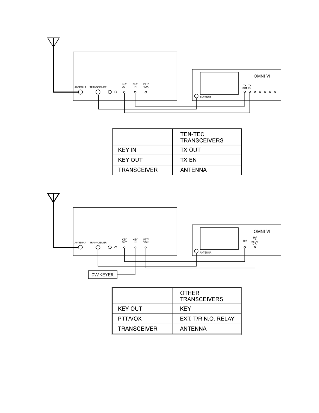
1.4 TRANSCEIVER
INTERCONNECTIONS: When using the
TITAN III with TEN-TEC transceivers with
TX EN and TX OUT connectors, follow the
diagram in Figure 1-1. The QSK-PTT/VOX
switch on the TITAN III should be in the
QSK position for all modes of operation.
This hook-up arrangement will work with
the OMNI series, PARAGON I and II,
PEGASUS, JUPITER, and ORION. Some
modern Yaesu transceivers are also
equipped with a full break-in keying loop
that can be utilized in a similar fashion. If
you are unsure about connecting this
equipment, please contact the TEN-TEC
factory for instructions.
When connecting the TITAN III with all
other transceivers, use the diagram in Figure
1-2. Note that the key or keyer must be
connected to the KEY IN jack on the
TITAN III, a cable is run from KEY OUT
to the key input jack on your transceiver,
and the line from the external T/R N.O.
relay contacts on the transceiver must be
connected to the PTT/QSK jack on the
TITAN III. When using this configuration,
the QSK-PTT/VOX switch on the amplifier
must be in the PTT/VOX position for SSB
operation and in the QSK position for CW
operation.
1.5 ANTENNA REQUIREMENTS:
The TITAN III amplifier is designed for use
with antennas resonant at the frequency of
operation and having an impedance within
the limit of 25 to 100 ohms, or an SWR of
2:1 or less (<10% reflected power). Note
that any SWR other than 1:1 will result in
TUNE and LOAD settings different from
those in the manual reference chart (Figure
2-1). The nominal load impedance of the
amplifier is 50 ohms. Antennas can exhibit
an SWR of more than 2:1 in some part of the
band. For operation under these conditions,
we recommend using an antenna matching
network that will enable the TITAN III to
work into a 50 ohm load for maximum
power transfer to the antenna.
CAUTION!!!
Never attempt to operate the TITAN III
without first connecting a suitable
antenna or 50 ohm resistive load of
sufficient power rating or
SERIOUS DAMAGE MAY RESULT!
1.6 GROUND CONNECTION: In the
interest of personal safety and to reduce the
possibility of stray RF pickup on
interconnecting cables, all station equipment
should be well grounded to earth and to
supply line ground bus. It is important to
strap all equipment chassis together with
short heavy leads. This ground bus may
then be tied to an external earth grounding
rod.
1.7 HIGH POWER OPERATION: The
TITAN III amplifier operates comfortably
at a maximum of 1500 watts output. New
owners often find that other components in
their station may not. Before operating at
this power level, be certain to check the
following items:
1. The coax from the TITAN III to the
feed point of your antenna must be
top quality RG-8 or better. We
recommend silver plated connectors
rather than chrome plated
connectors. Make sure that all coax
connectors are tight.
2. All coax switches or relays in the
feed line must be rated at 1500 watts
or higher. NEVER ACTIVATE INLINE SWITCHES WHILE
TRANSMITTING.
3. Verify that the components in your
antennas are rated for the TITAN III
maximum power levels (dipole
center insulator, end insulators,
baluns, traps, etc.) Make sure that
all radiating sections are well clear
of metallic objects such as rain
gutters and antenna supporting
1-2
Page 12

structures. For the first few hours of
operation, check the SWR
frequently. Any increase in
reflected power is an indication that
something between the amplifier and
the antenna elements, including the
end insulators, is heating and must
be corrected.
4. A solid earth ground is often
essential. Every station will have a
unique electrical ground due to
location of equipment, distance
between units, distance from house
wiring ground rod, distance from RF
ground rod, etc. Keep equipment
ground straps as short and thick as
possible and RF ground rod as close
to the station as possible.
5. If you use an antenna tuner, make all
SWR/matching adjustments with the
TITAN III in the STANDBY mode
using transceiver low power only.
6. If any of your home entertainment
electronic devices have RF leaks, the
TITAN III may find them. If you
are not familiar with standard
procedure for controlling this type of
interference, consult the ARRL
Radio Frequency Interference
Manual.
depending on input RF drive level. A
negative output voltage will be present at the
ALC jack only when the TITAN III is in the
OPERATE mode and the input RF drive is
above the threshold setting. Leave this
control fully clockwise if you have no
requirement for external ALC.
1.9 COOLING SYSTEM: The TITAN III
uses a pressurized cabinet with the main air
intake through the right front side of the
chassis and exhaust through the tube
chimneys on the right rear top of the
amplifier. It is safe to operate the amplifier
as long as there are no impediments to the
flow of air near the air intakes and/or the
exhaust.
1.8 ALC: Most solid state transceivers do
not provide connection for ALC input and it
is unnecessary to make any external ALC
connection to these rigs. The ALC output
jack is used primarily with tube-type
transmitters or transceivers with a negative
going ALC system. The ALC ADJUST
control is used to set the threshold for proper
ALC action. This is -1 to -15 VDC
1-3
Page 13
TITAN III
TITAN III
FIGURE 1-1 T/R CONNECTIONS FOR TEN-T EC
TRANCEIVERS WITH TX O U T & TX EN
TITAN III
TITAN III
FIGURE 1-2 T/R CONNECTIONS FOR OTHER
TRANCEIVERS WITHOUT TX OUT & TX EN
1-4
Page 14

CHAPTER 2
OPERATING INSTRUCTIONS
2.1 INTRODUCTION: The following
instructions will enable the operator to quickly
place the TITAN III in operation. Included are
descriptions of the front panel controls and rear
panel connections, followed by a detailed tuneup procedure. Refer to Chapter 3 operation and
safety tips.
2.2 FRONT PANEL CONTROLS: The front
panel controls and their functions are described
below.
2.2.1 BAND SWITCH: This switch selects the
desired frequency of operation. This is a ten
position switch that covers the 160 meter to 10
meter bands. NOTE: A built-in switch stop
prevents operation in the 10 and 12 meter bands.
For 10 and 12 meter operation you must contact
the factory for an authorized modification kit.
2.2.2 TUNE: This control adjusts variable
capacitor C1 to provide resonance at the
operating frequency. Figure 2-1 shows the
approximate settings for both the TUNE and
LOAD controls on each band. Keep in mind
that the settings in this chart are for operation
into an ideal 50 ohm resistive load. There is
also a blank log chart that you may use to record
the actual control settings for your antennas.
2.2.3 LOAD: This control adjusts variable
capacitor C2 for the proper amplifier output
loading. See Figure 2-1.
2.2.4 POWER: This switch routes the AC line
to the primary of the low voltage supply. When
on, the TITAN III will power up and the
indicator light in the POWER switch will light.
2.2.5 OPERATE/STANDBY: This switch,
when in the OPERATE position, places the
amplifier online. When in the STANDBY
position, the amplifier is bypassed and only
the transceiver power is routed to the
antenna. When in the OPERATE position,
the indicator light in the switch will light.
NOTE: No high voltage will be read on the
metering when this switch is in STANDBY.
The OPERATE/STANDBY switch also
serves as the plate current trip-off circuit
reset switch. At 1.5 amps plate current, the
plate current trip-off circuitry will activate.
The lighted segment of the
OPERATE/STANDBY switch will go out
when plate current trip-off has occurred. To
reset, switch back to STANDBY and
immediately back to OPERATE. The
lighted segment of the switch should now be
lit again and the amplifier is ready to use.
2.2.6 QSK/PTT: This switch, when in the
QSK position, configures the key circuits for
CW/QSK operation. For late model TENTEC transceivers with TX EN and TX OUT
connectors, or late model Yaesu transceivers
connected using a full break-in keying loop,
this position is used for all modes of
operation. Placing the switch in the PTT
position allows the TITAN III to be
controlled by the PTT/VOX input jack
rather than the KEY IN/KEY OUT loop.
2.2.7 MULTIMETER SWITCH: This
switch connects the right hand meter to
monitor various amplifier parameters.
A. Plate voltage (Ep) - When in this
position, the meter reads plate voltage.
This voltage is line voltage dependent
at a ratio of 12.5 V plate per 1 V line.
Plate voltage is approximately 3000
VDC at a line voltage of 240 VAC.
Therefore, at a line voltage of 250
2-1
Page 15

VAC the meter will read a little higher
(3125 VDC).
B. Screen current (Is) - When in this position,
the meter is paralleled with a resistor in
series with the screen supply. This
monitors screen grid current. The upper
limit for screen current is 75 mA.
NEVER OPERATE THE TITAN III IN
EXCESS OF 75 mA SCREEN GRID
CURRENT. A warning zone indicator is
used on the face of the meter to alert the
operator. In addition to the analog meter,
the screen overdrive LED indicates
excessive screen current.
C. Forward power (FWD) - When in this
position, the meter is connected to the
forward port of a bridge circuit at the
antenna output. This measures forward
RF output power. It is, however, more
load dependent than an external
wattmeter. If your antenna is far from
resonance, the accuracy is not as good and
power measurements should be made
externally.
D. Reflected power (REF) - When in this
position, the meter is connected to the
reverse port of the bridge at the antenna
output. Reflected power is read at 1/10
indication scale of forward power (200
watts full scale).
2.2.8 PLATE CURRENT METER:
Full time plate current metering is provided
by the left analog meter.
2.2.9 OVERDRIVE: These two LEDs indicate
grid overdrive conditions.
A. When the screen overdrive LED is lit, the
screen current is approaching or has passed its
limit. Reduce drive from the transceiver
immediately and retune.
B. When the control grid overdrive LED is
lit, the control grid current is approaching or has
passed its limit. Reduce drive from the
transceiver immediately and retune.
2.2.10 WAIT: This LED indicates a 3 minute
warm-up period for the tube at initial power up.
After being turned on for 3 minutes, the wait
LED goes out and the TITAN III can be
placed in the operate mode.
2.2.11 PEAK POWER BARGRAPH:
This meter is connected to the bridge at the
antenna output through an emitter follower
to monitor peak RF output power. When the
red LED is lit, 1500 watts output has been
reached.
2.3 REAR PANEL CONNECTIONS
AND CONTROLS: The rear panel
connections and their functions are
described below.
2.3.1 TRANSCEIVER: This is a standard
SO-239 receptacle designed for a mating
PL-259 plug. RG-58U or similar 50 ohm
coax is required to connect the TITAN III to
the transceiver.
2.3.2 ANTENNA: This is a standard SO239 receptacle designed for a mating PL-259
plug. RG-8 or similar 50 ohm coax rated for
1500 watts is required for connection to the
antenna.
2.3.3 KEY IN: This jack is the input for
the TITAN III transmit/receive relay
system. When used with late model TENTEC transceivers, this jack is connected to
the TX OUT connector on the transceiver.
When used with other transceivers, a key or
keyer is connected to this jack for QSK CW
operation.
2.3.4 KEY OUT: This jack is a protected
output from the TITAN III which passes the
KEY IN to the transceiver after all relays in
the TITAN III have closed and it is ready to
transmit. When used with late model TENTEC transceivers, this jack is connected to
the TX EN connector on the transceiver.
When used with other transceivers, this jack
is connected to the transceiver CW key input
jack.
2.3.5 PTT/VOX: This jack is an input to
the TITAN III transmit/receive relay
2-2
Page 16

circuits. When used with late model TEN-TEC
transceivers, this jack is not used. When used
with other transceivers, this jack is connected to
the normally open (grounding) contacts of the
relay key out jack of the transceiver.
2.5 TUNE UP PROCEDURE: The
following section describes important points
to observe during tune up. A suggested
procedure for safely tuning up the TITAN
III is included.
2.3.6 ALC: This jack provides a negative going
ALC voltage, used primarily with tube type
transmitters/transceivers. See section 1.8 for
detailed information.
2.3.7 ALC CONTROL: This control adjusts
the ALC threshold voltage from approximately 1 to -15 VDC depending on RF input from the
transceiver.
2.3.8 AC LINE: This cable is connected to
standard 240 VAC. Be sure the line used to
power the TITAN III is capable of supplying 20
amps of current at 240 VAC, and that it is
protected by either fuses or circuit breakers of
20 amps. Wire size of the AC feed line should
be at least 10/2 with ground or larger.
2.3.9 LINE FUSES: Primary line fuses (ABC-
20) are accessible through these panel fuse
holders. Replace with ABC-20 or comparable
fuses only.
2.4 INITIAL TURN-ON: The following
steps should be followed when turning on your
TITAN III.
A. Set multimeter switch to the plate voltage
(Ep) position.
B. Place the power switch to ON. If any of
the following do not occur, press OFF at
once and investigate before proceeding.
1. The power switch light should light.
2. The meter lights should light.
3. The fan motor should start and air
flow should be felt at the exhaust port
on top of the amplifier.
4. The wait LED should light.
5. All meter indications are zero.
6. All other LEDs are not lit.
NOTE: HIGH VOLTAGE IS PRESENT ONLY
IN THE OPERATE MODE. THE OPERATE
MODE IS DISABLED FOR 3 MINUTES
WHILE THE WAIT LED IS LIT.
2.5.1 CHECKS TO MAKE BEFORE
TUNING UP: Check the load connected to
the amplifier. This can best be done by
leaving the TITAN III in the BYPASS
mode and using only the transceiver output
power. Use a reliable SWR bridge or
wattmeter to determine the SWR of the load
(antenna) connected to the amplifier. If the
reflected power is less than 10% of the
forward power, the VSWR is less than 2:1.
If the reflected power is 4% or less, the
VSWR is 1.5:1 or lower. A VSWR of 2:1 or
less is essential.
2.5.2 IMPORTANT POINTS TO
REMEMBER: The most important
parameters to observe during tune up are the
control grid current and screen grid current.
Excessive grid current even for a relatively
short period of time can and will damage the
tube. If grid currents are not exceeded, the
4CX800A tubes will deliver many years of
trouble free service. In the TITAN III the
control grid is monitored by front panel
LED indicator. When control grid current is
exceeded, the GRID overdrive LED will
light. Reduce the drive immediately and
retune the TITAN III. Screen grid current is
monitored by the multimeter, (when in the Is
position) and by an LED overdrive indicator
continuously. Screen grid current should be
kept to a minimum during tune up and
always in a positive direction. When screen
current is exceeded the SCREEN overdrive
LED will light. Reduce drive immediately
and retune. After tune up, erratic lighting of
either overdrive indicator could indicate
breakdown in the load (antenna
components). Reduce drive and check for
arcing or heating of baluns, coax or other
elements. Brief blinks of the LEDs at initial
power-on or key-down are OK.
2-3
Page 17

2.5.3 SUGGESTED TUNE UP
PROCEDURE: Following is the
recommended procedure for safe and proper
tune up of the TITAN III.
A. Set the band switch to the desired band.
For 160 meter operation between 1.9 and
2.0 MHz, use position 160B.
B. Set the multimeter switch to the Ep
position.
C. After the wait LED goes out, place the
STANDBY/OPERATE switch to
OPERATE. The STANDBY/ OPERATE
switch will light and high voltage is
indicated on the multimeter (nominal
3000 VDC).
D. Set the meter switch to the Is position.
Always monitor Is (screen grid current)
with the multimeter during tune up. Use
FWD and REF positions momentarily for
checking output power. Output power
can also be monitored on the LED
bargraph power meter. Always monitor
the overdrive LEDs. Reduce drive and retune the amplifer if either is lit.
E. For initial tune up you may set the TUNE
and LOAD controls to their center
positions. Alternatively you may refer to
the suggested settings in the chart in
Figure 2-1. Keep in mind that these
settings are for operation into an ideal 50
ohm load and will vary with your
installation.
F. Turn the transceiver RF output control to
between 10 and 20 watts. Note: at very
low transceiver power outputs (<10 watts)
the amplifier may not respond when
attempting to tune up. This is normal.
Increase drive power slightly and continue
tune up. IF AT ANY TIME THE TITAN
III DOES NOT RESPOND AS
EXPECTED, REMOVE DRIVE POWER
IMMEDIATELY AND CORRECT THE
PROBLEM BEFORE CONTINUING.
G. Key the transceiver and slowly increase
the drive power until you see the plate
current increase.
H. Adjust the TUNE and LOAD controls for
a peak in RF power output. Increase the
drive power until screen current appears
and adjust the TUNE control for a
peak in screen grid current. Adjust
the LOAD control clockwise to
reduce screen grid current if it is being
driven above 60 mA at your desired
power output. Always re-peak the
screen current and RF output with the
TUNE control after any LOAD
control adjustments. Watch the plate
current meter during tune up. If the
plate current is much over 1.0 Amp at
the TUNE control Is/RF peak, reduce
loading with a small counterclockwise rotation of the LOAD
control (toward higher numbers on the
dial skirt) and re-peak the TUNE.
Remember: Readjust the TUNE
control for a screen grid current and
power output peak each time you
adjust the LOAD control. There will
be some interaction between these
controls. Too-high peaked screen
current can always be reduced at the
expense of higher plate current by
increasing the loading (clockwise
LOAD adjustment).
I. Gradually increase the drive level
from the transceiver until you reach
the desired output power level while
carefully touching up the LOAD and
TUNE controls until both plate and
screen currents read at or slightly
above mid-scale. Screen grid current
of 45 to 60 milliamps is normal for
1500 watts output. NEVER EXCEED
75 MILLIAMPS SCREEN GRID
CURRENT.
J. Once you have the amplifier tuned up
and operating on the desired
frequency, you can log the LOAD and
TUNE settings in the chart provided
(Figure 2-2). These settings should be
repeatable for the same frequency,
antenna, and SWR when used in the
future.
Note: Markings 0-10 on the dial skirts
correspond to 0-100% PI-L network
capacitance vaues.
2-4
Page 18

BAND
FREQUENCY
MHz
LOAD TUNE
160A
160B
80
75
40
30 10.120 2 1
20
1.820
1.980
3.500
3.980
7.040
7.250
14.050
14.250
8
7
8.5
5.5
3.6
3.5
1.6
1.5
5
7
7.5
5
1.6
1.5
1
0.5
17 18.110 2.0 1
21.050
15
21.4
12 24.900 2.0 1.5
28.100
10
29.5
1.5
1.5
1.5
1.5
1.5
1
2
0.5
FIGURE 2-1 MODEL 417A TUNING CHART
FOR AN IDEAL 50 OHM LOAD
2-5
Page 19

BAND FREQUENCY LOAD TUNE ANTENNA
NOTES
2-6
FIGURE 2-2 MODEL 417A TUNING LOG
Page 20
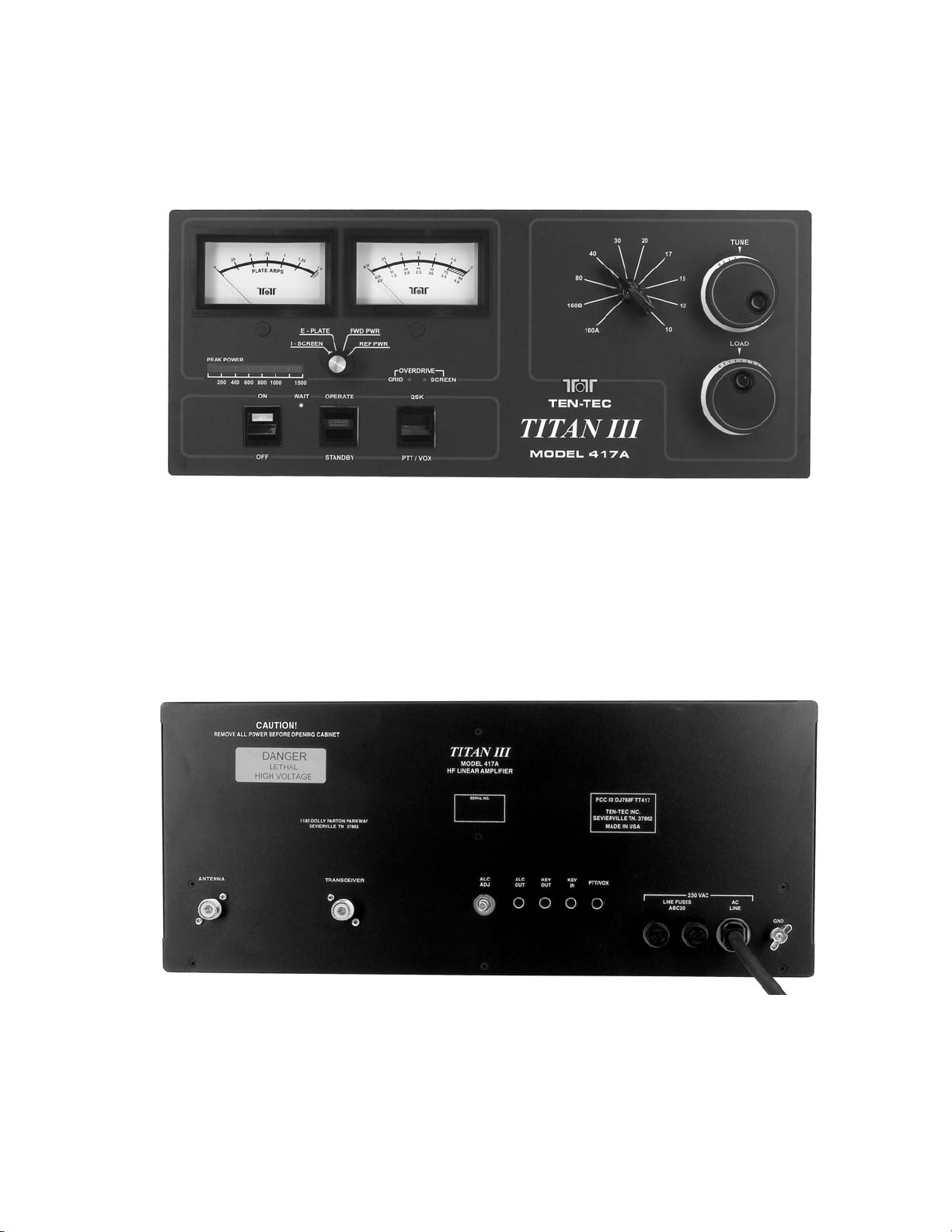
FIGURE 2-3 TITAN III FRONT VIEW
FIGURE 2-4 TITAN III REAR VIEW
2-7
Page 21
2-8
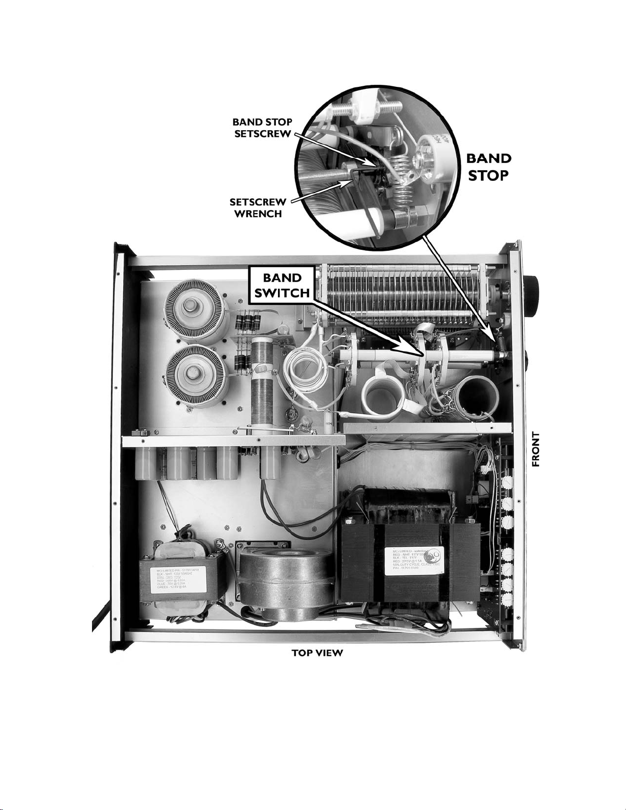
FIGURE 2-5 TITAN III TOP VIEW
Page 22
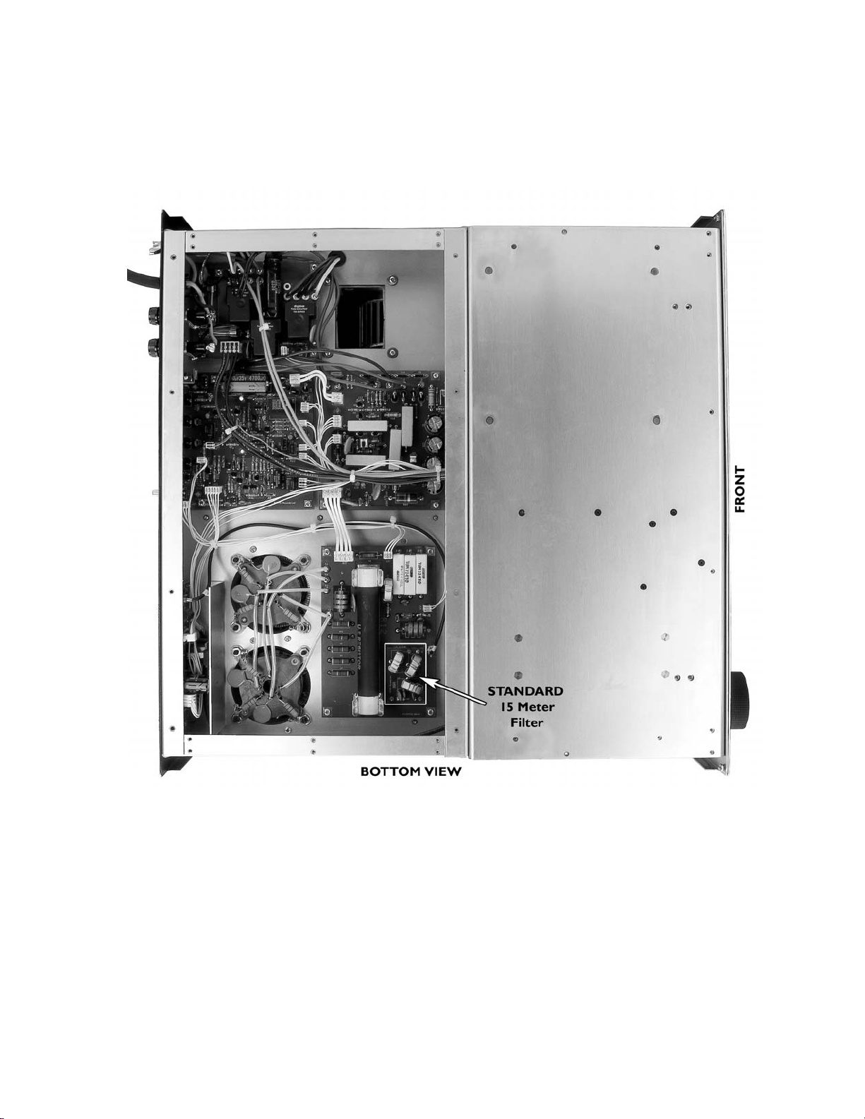
FIGURE 2-6 TITAN III BOTTOM VIEW
2-9
Page 23

CHAPTER 3
OPERATION AND SAFETY
3.1 INTRODUCTION: The following paragraphs provide additional information for operation
of and safety from your TITAN III amplifier.
3.1.1 HIGH POWER TETRODES: The 4CX800As are very rugged and normally operate
with a large margin of safety in the TITAN III. They will deliver outstanding service for many
years if not damaged by abuse...especially excessive grid current or blockage of cooling air flow.
KEEP THE AIR INTAKE AND EXHAUST VENT AREAS
COMPLETELY CLEAR !!!
WARNING !!! DO NOT ALLOW THE SCREEN GRID CURRENT TO
EXCEED 75 mA!
3.1.2 INTERLOCKS: The TITAN III is equipped with interlock switches intended to shut off
the power and short out the high voltage power supply when the cover is not securely fastened in
place. These protective interlocks are provided to protect you from POTENTIALLY FATAL
ELECTRIC SHOCK resulting from accidental contact with lethal voltages inside the amplifier.
However, you should never depend on interlocks alone to protect you by removing dangerous
voltages. ALWAYS DISCONNECT THE AC LINE CABLE TO THE TITAN III BEFORE
REMOVING THE TOP COVER.
WARNING !! THE AMPLIFIER SHOULD NEVER BE
ENERGIZED WITH THE COVERS REMOVED!!
DO NOT DEFEAT THE INTERLOCK SAFETY
SWITCHES!!
3.1.3 FUSES: Except in rare instances of component failure, blowing one or both primary fuses
indicates that maximum safe average power capabilities of the amplifier have been exceeded.
3-1
Page 24
CHAPTER 4
MAINTENANCE AND TROUBLESHOOTING
4.1 INTRODUCTION: If you encounter a
problem, the troubleshooting hints listed in
TABLE 4-1 below will help isolate the
nature of the problem.
TABLE 4-1 TROUBLESHOOTING HINTS
SYMPTOM POSSIBLE CAUSE/CURE
1. Will not turn on: nothing happens
when the ON switch is activated.
4.2 MAINTENANCE: The amplifier
compartment, particularly areas around high
voltage components should be cleaned often
(using a soft bristled brush and vacuum
cleaner) to prevent visible accumulation of
dust. DO NOT blow air directly into the fan
input: this can over rev the motor and
damage the bearings.
A] Fuse missing or open.
B] House wiring incorrect or breaker open.
C] Power cable to amplifier disconnected.
D] Fuse on HV-AC board A9 (81945) open.
E] Problem with low voltage power supply
on QSK board A11 (81949)
2. Lights turn on but no high voltage.
3. Relays A9K2 and A9K3 on 81945 HVAC board close but relay K1 does not.
Plate Voltage drops when RF is applied.
4. Relays A9K1, A9K2, A9K3 on 81945
HV-AC board close but no high voltage
when switched to OPERATE mode.
A] No HV will be present until amp is
switched to OPERATE mode (and timed out).
A] A9Q1 on 81945 HV-AC board is
defective.
B] A9K1 on 81945 is defective.
A] Interlock open, cover not tight
B] A9K2, A9K3 defective.
C] HV short to ground.
D] High voltage transformer disconnected.
E] High voltage bridge open.
4-1
Page 25

TABLE 4-1 TROUBLESHOOTING HINTS (Continued)
5. Relays A9K1, A9K2, and A9K3 close at turn
on, but line fuses blow.
6. Amplifier won’t drive, zero grid and plate
current, high input SWR .
7. Grid overdrive LED lights with no drive. A] A10Q7 on 81950 Screen Supply shorted or
8. Screen overdrive LED lights with no drive. A] A10R23 on 81950 Screen Supply open or
9. Amplifier difficult to drive, little or no output,
high plate current (may be accompanied by a
“frying sound”).
10. Excessive plate current in receive mode. A] Defective bias circuit, 81950 board (A10).
A] High voltage shorted at crowbar or
elsewhere.
B] Shorted tube.
C] Leaky electrolytics in high voltage supply.
A] Defective cable from transceiver to
amplifier.
B] Input relay A4K2 on 81951 SWR board
defective.
C] Input filter A7 or A8 on 81946 Input
Matching board (A6) loose or damaged.
leaky.
B] Shorted or leaky tube.
increased in value.
B] Low or no high voltage. TURN OFF THE
AMPLIFIER IMMEDIATELY.
A] Band switch in wrong position.
B] Excessively high load SWR.
C] Defective output relay A4K1 on 81951
SWR board.
D] Arcing in tank circuit or antenna feed
line.
B] Shorted grid / cathode in tube.
11. Transceiver does not key using key-in/keyout loop.
12. Transceiver stays keyed in receive mode.
May be accompanied by loss of receive signal.
4-2
A] Key-in and key-out lines reversed at
amplifier or at transceiver.
B] Defective key line cables.
C] Defective relay control circuit on 81949
QSK board (A11).
A] Relay A4K1 on 81951 SWR board stuck.
B] Shorted key-in or key-out cable.
C] Defective relay control circuit on 81949
QSK board (A11).
Page 26

CHAPTER 5
CIRCUIT DESCRIPTIONS AND ILLUSTRATIONS
5.1 INTRODUCTION The following sections contain detailed circuit board subassemblies
used in the Model 417A. Also included are circuit trace drawings and detailed component
layout diagrams. These drawings are followed by a schematic diagram for the complete
amplifier.
5.2 INPUT MATCHING BOARD A6
(81946)
filter, impedance matching networks,
ALC
The 15M INPUT FILTER BOARD A7
(81953) is the standard input filter shipped
with the TITAN III. This is a five pole
elliptic filter consisting of L1, L2, L3, C1,
C2, and C3. This filter provides increased
roll-off of frequencies above the 15 meter
band. An optional 15/10M INPUT
FILTER BOARD A8 (81954) is available
from TEN-TEC to qualified amateur radio
operators, upon receipt of a copy of their
amateur radio license.
This board contains the input
and
circuits.
Note: Operation on the 10 or 12 meter
bands will also require additional
modifications to the bandswitch
assembly. Please contact the factory for
instructions or further information.
The impedance matching network of
R4–R12 and L3 on assembly A6 matches
the input of the 4CX800As to the driver
impedance of approximately 50 Ohms.
The ALC circuit on A6 samples the
input RF power to the amplifier. A6D1
rectifies this sample and produces a
negative voltage proportional to input
power for control of some exciters. The
ALC threshold is set by potentiometer
A11R52, located on the rear panel. Turn
this control fully clockwise if ALC is not
used.
5-1
Page 27
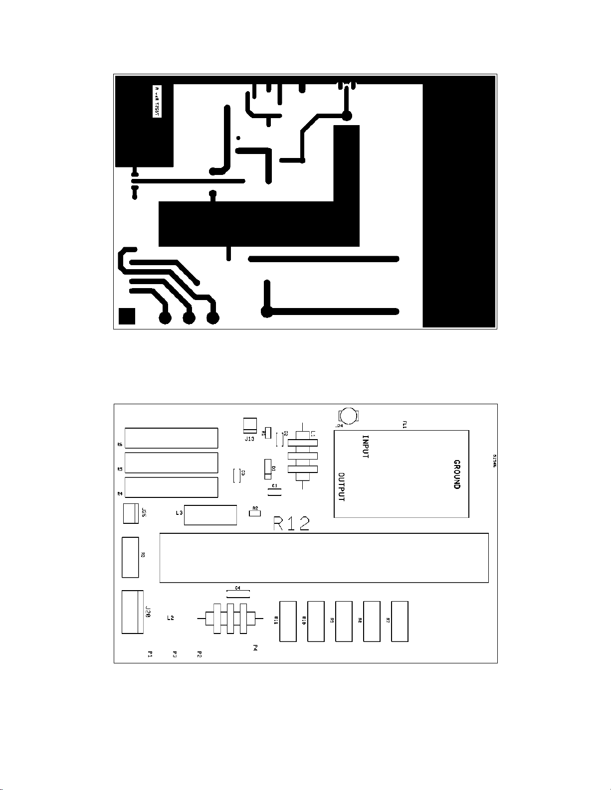
FIGURE 5-1 INPUT MATCHING BOARD (ASSEMBLY A6) CIRCUIT TRACE
AS VIEWED THROUGH BOARD
5-2
FIGURE 5-2 INPUT MATCHING BOARD (ASSEMBLY A6)
COMPONENT LAYOUT TOP VIEW
Page 28
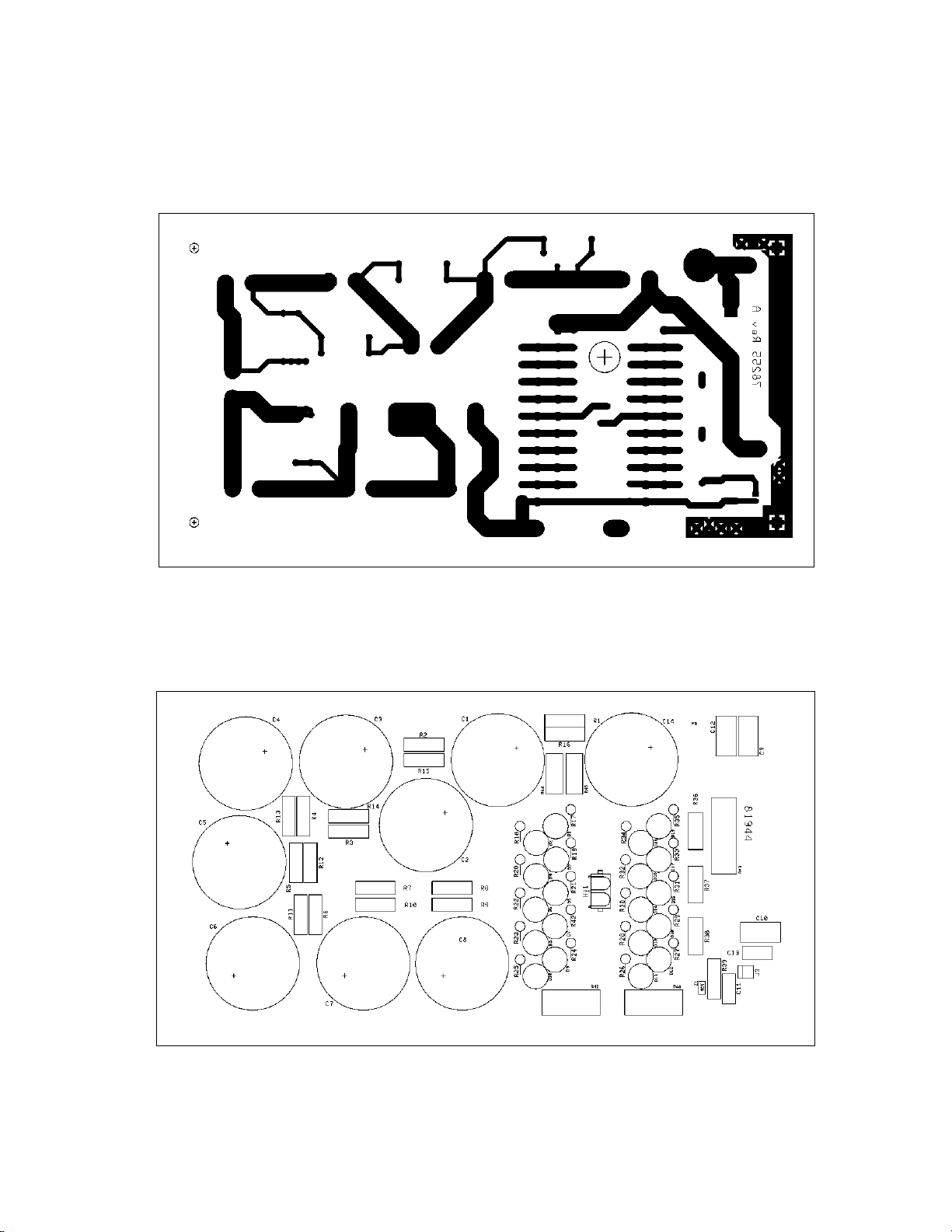
H.V. POWER SUPPLY BOARD A2 (81944) This board contains the high voltage rectifier
bridge (D1 – D20), H.V. filters (C1 – C8 and C14), and H.V. meter circuits.
FIGURE 5-3 HIGH VOLTAGE RECTIFIER BOARD (ASSEMBLY A2)
CIRCUIT TRACE AS VIEWED THROUGH BOARD
FIGURE 5-4 HIGH VOLTAGE RECTIFIER BOARD (ASSEMBLY A2)
COMPONENT LAYOUT TOP VIEW
5-3
Page 29
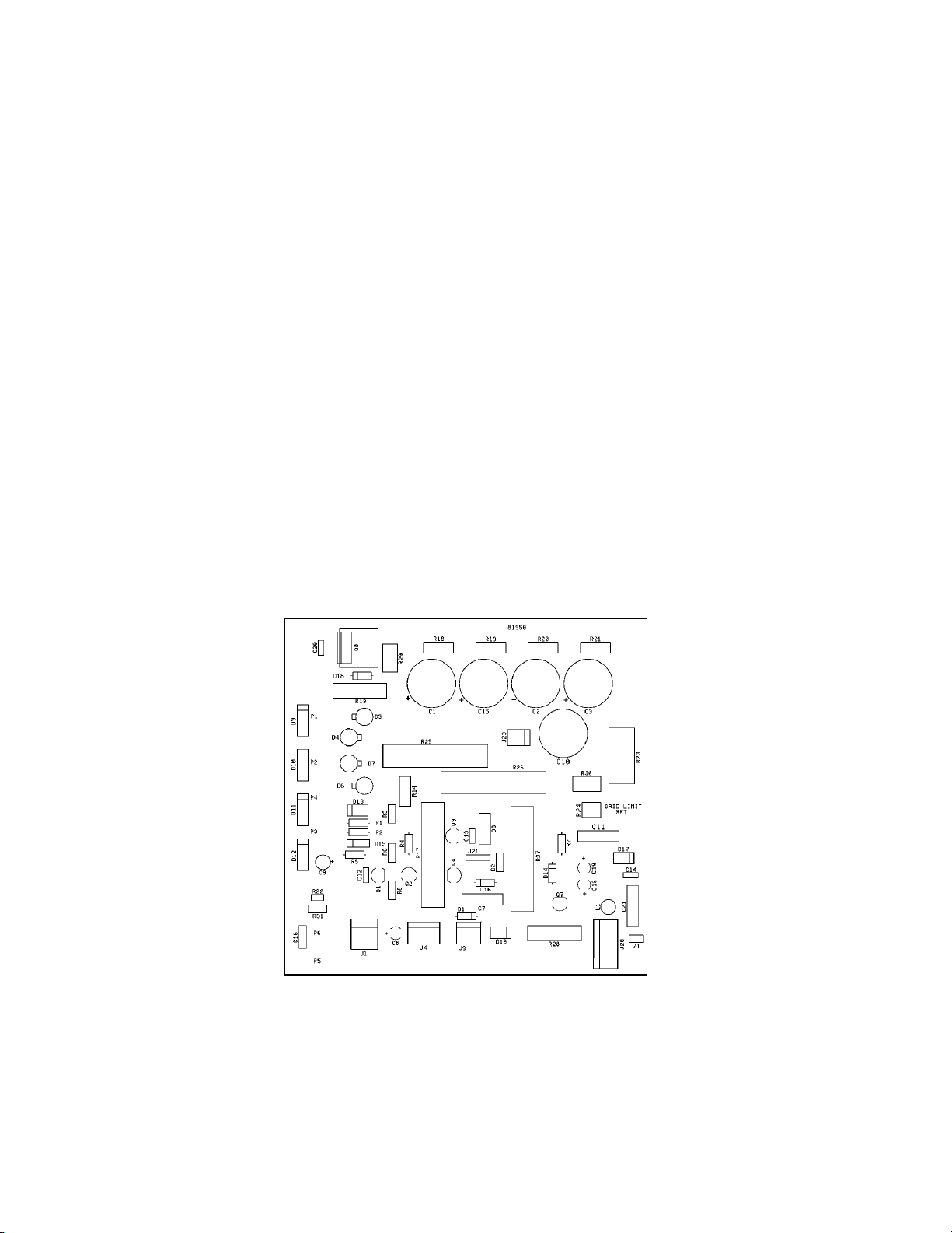
5.4 SCREEN SUPPLY AND GRID BIAS BOARD A10 (81950) This board contains the
screen supply, grid bias supply, and protective circuits for the 4CX800As. The screen
voltage is rectified by diodes D4 – D7 and filtered by C1 – C3 and C15. This DC voltage is
then regulated by pass element Q8. Load resistors R25 – R27 provide a current drain to
insure screen current remains in the positive direction. MOV Z1 protects the power supply in
the event of tube arc and insures the screen voltage can’t surge above 450 VDC. R23
provides a voltage drop proportional to the screen current to drive the front panel screen
current meter.
Grid bias voltage is rectified by D13, then filtered by C10. Q1 senses the key condition
and via Q2 and Q4 switches zener diodes D2, D8 and D16 in during key down and out during
key up. This zeners the bias voltage to approximately –55 VDC during TX and –100 VDC in
RX. Due to differences in tubes, J21 allows adjustment of grid bias in 4 settings:
-47V Pins 1 and 3 shorted
-55V Pins 2 and 3 shorted
-60V Pins 1 and 2 shorted
-68V no pins shorted
This adjustment is factory set to match the tubes shipped with the amp. If the tubes are ever
replaced, the jumper setting should be selected to produce approximately 200 – 400 mA of
plate current when keyed with no drive. The circuitry of Q7 senses grid current and begins to
fold back grid bias toward cutoff as grid power approaches 2 watts. Zener diode D1 provides
regulation for the negative 16 VDC power supply to run the meter circuits on the meter
switch board and the relay hot-shot circuit on the SWR board.
5-4
FIGURE 5-5 SCREEN SUPPLY BOARD (ASSEMBLY A10)
COMPONENT LAYOUT TOP VIEW
Page 30
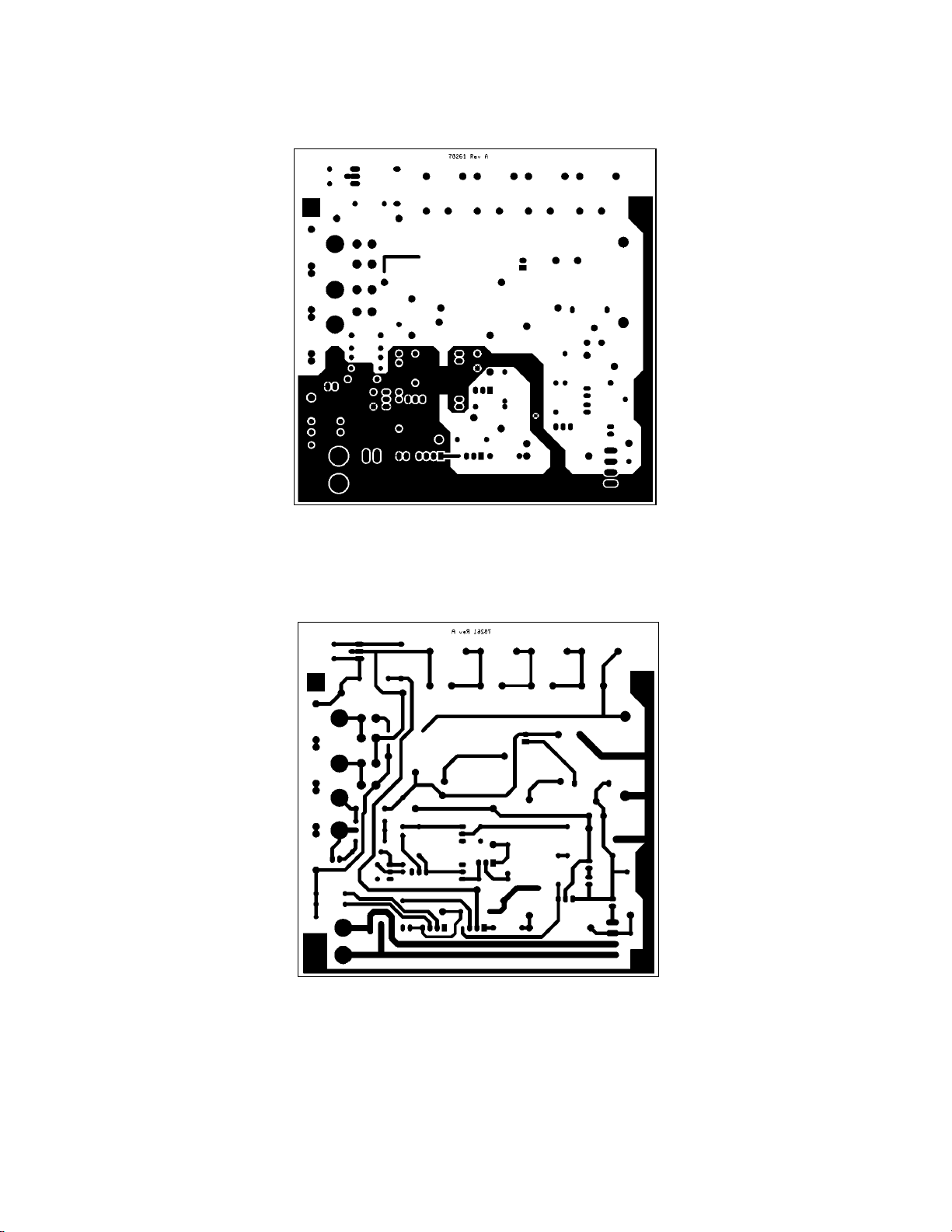
TOP SIDE COPPER
BOTTOM SIDE COPPER
FIGURE 5-6 SCREEN SUPPLY (ASSEMBLY A10) CIRCUIT LAYOUT
VIEWED THROUGH BOARD FROM TOP
5-5
Page 31
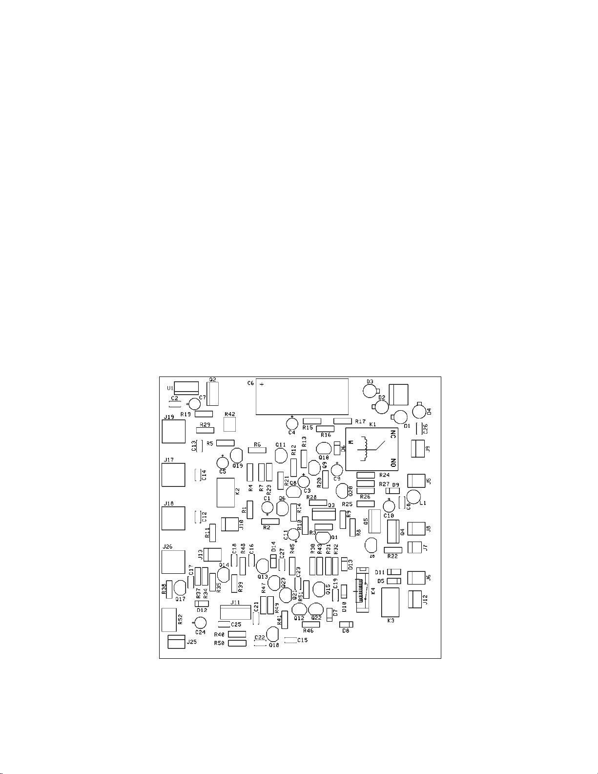
5.5 QSK BOARD A11 (81949) This board contains the low voltage supply, turn-on relay
sequencing circuits, and T/R relay control.
The low voltage is rectified by D1 – D4 and filtered by C6. U1 and Q2 provide regulation
for all low voltage circuits except the negative 16 VDC supply.
After a 3 minute warm-up period determined by RC time constant of R4 and C5, Q19 and
Q11 will conduct, turning on the pass element Q5. This initiates amplifier power up.
When the STANDBY/ OPERATE switch is put in the OPERATE position, this voltage is
applied to relay sequencing circuits Q3, Q6, Q4 and Q10. These circuits insure plate and
screen voltages arrive at and leave the tube in the proper order.
Q20 senses plate current and disables the amplifier when plate current parameters are
exceeded (such as excessive plate current during a tube arc). Both plate voltage and screen
voltage are removed when plate current of 1.5A is reached.
The QSK CONTROL CIRCUIT consists of Q12-Q18 and Q21-Q23. This circuit samples
input key requests, standby/operate modes, power on/off state, state of output relay, and RF
presence at the antenna connection and input of the amp. Hot switch protection is provided
regardless of mode. In the QSK mode, using the key in / key out loop, the key in request
from the transceiver is tailored by the QSK CONTROL circuit to insure smooth QSK action
of the input and output relays.
K2 senses power OFF or STANDBY and places the key circuit in bypass for exciter
operation in barefoot mode.
K3 senses OPERATE mode and routes the key request to the amplifier control circuits.
K4 passes the “key in” to the KEY OUT jack when all relays are closed and ready for RF.
5-6
FIGURE 5-7 QSK BOARD (ASSEMBLY A11) COMPONENT
LAYOUT TOP VIEW
Page 32
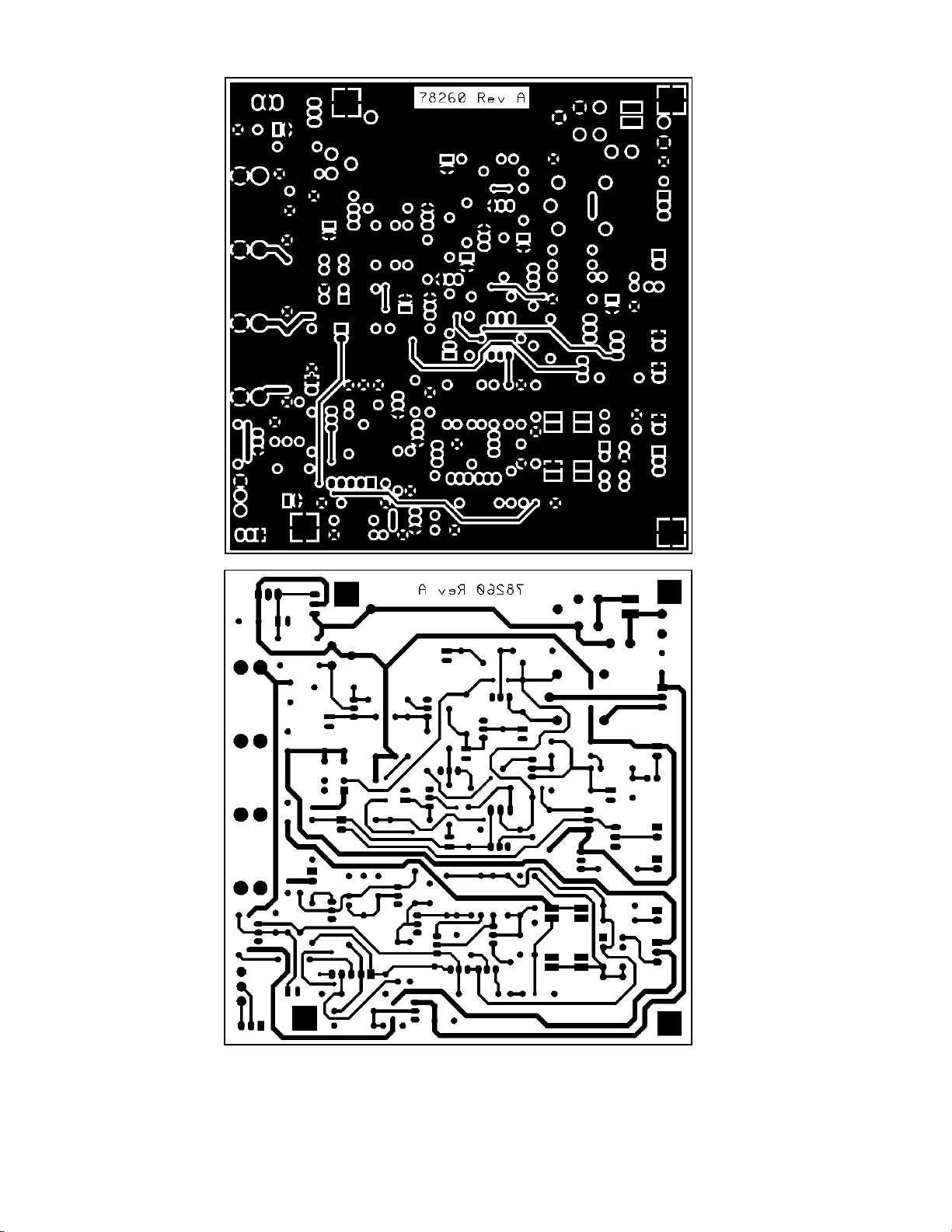
FIGURE 5-8 QSK BOARD (ASSEMBLY A11) TOP AND BOTTOM
CIRCUIT TRACES VIEWED THROUGH BOARD FROM TOP
5-7
Page 33
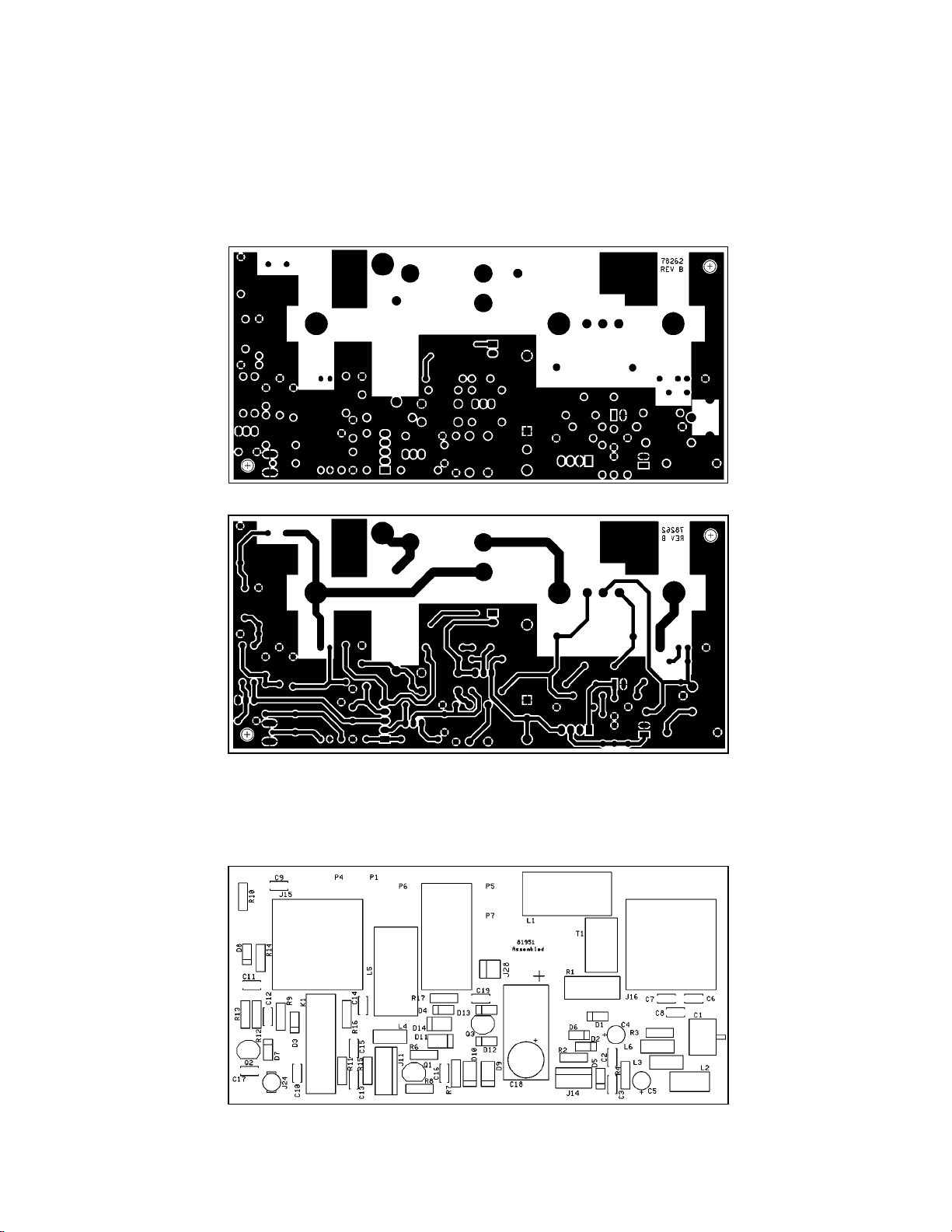
5.6 SWR BOARD A4 (81951) This board contains the input relay K1, output relay A14
(81959), hot-shot circuit Q3-C19, and the SWR bridge T1 for output power sampling.
FIGURE 5-9 SWR BOARD (ASSEMBLY A4) CIRCUIT TRACE
VIEWED THROUGH BOARD FROM TOP
TOP COPPER
5-8
BOTTOM COPPER
FIGURE 5-10 SWR BOARD (ASSEMBLY A4)
COMPONENT LAYOUT TOP VIEW
RELAY
ASSEMBLY A14
Page 34
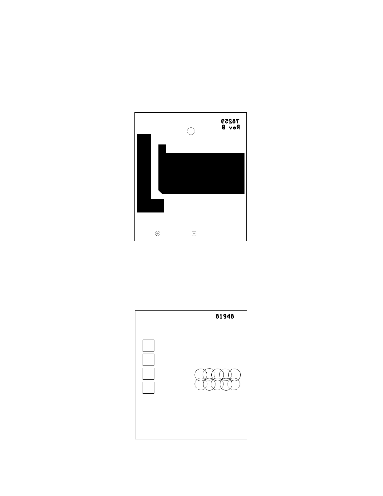
5.7 PLATE BOARD A3 (81948) This board contains the parasitic suppressors and coupling
capacitors to connect the 4CX800A plates to the amplifier tank circuit.
FIGURE 5-11 PLATE CONNECTOR BOARD (ASSEMBLY A3)
CIRCUIT TRACE VIEWED THROUGH BOARD
FIGURE 5-12 PLATE CONNECTOR BOARD (ASSEMBLY A3)
COMPONENT LAYOUT TOP VIEW
C1
C2
C3
C4
R1 R2 R3
R6R7
R4 R5
R8R9R10
5-9
Page 35
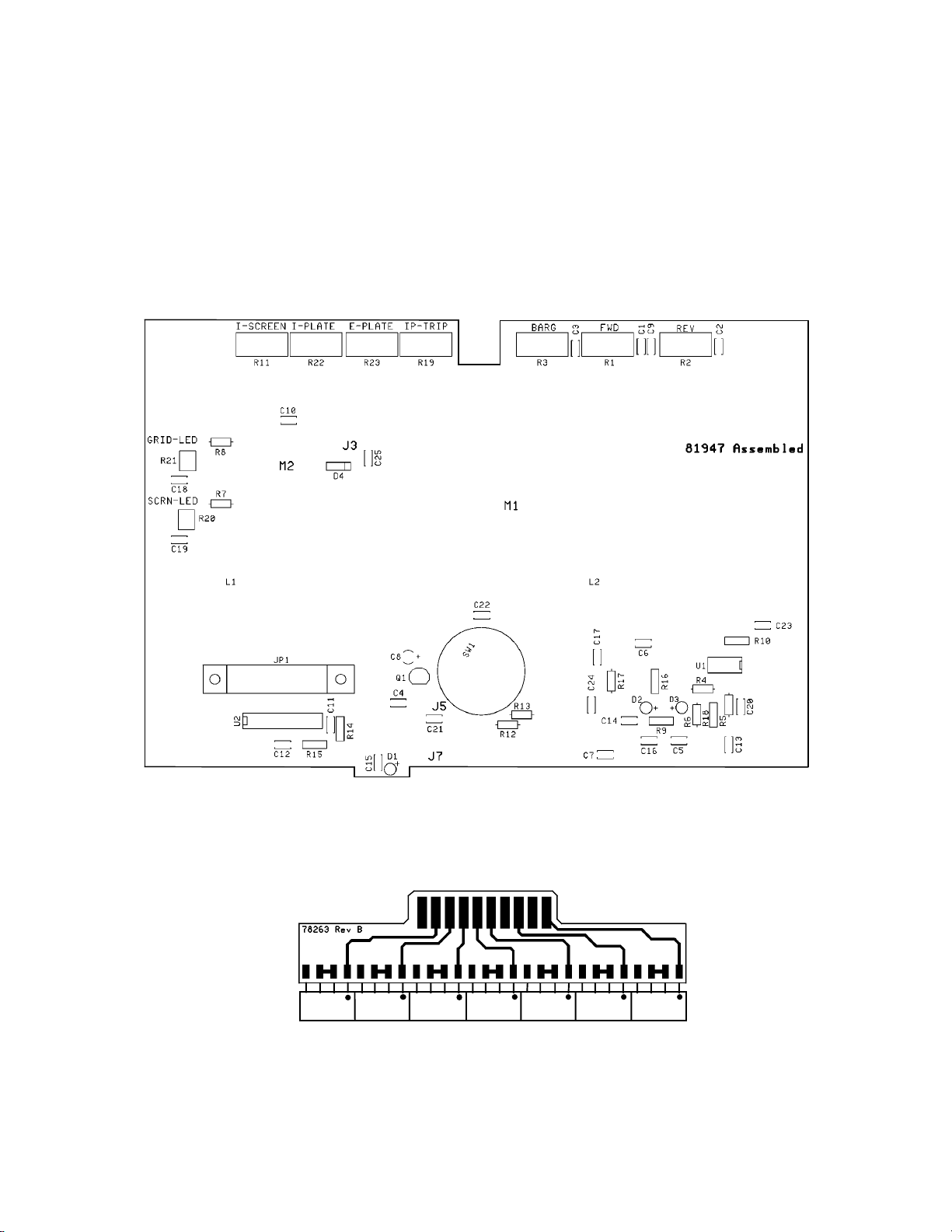
5.8 METER/SWITCH BOARD A12 (81947) and DISPLAY BOARD A13 (81952)
This board contains the metering circuits for the front panel meters. A12S1 selects the
parameter to be monitored. This selection is then sent to multimeter M1. The multimeter has
three calibrated scales for measuring plate voltage, screen current and forward or reflected
RF power. The KW scale should be divided by ten when measuring reflected power.
A12U1 samples screen and control grid current and drives the appropriate LED to indicate
excessive current of either screen or control grid. Q1 samples forward RF power voltage
from the SWR board. This voltage is peak-held by C8 and sent to U2 to drive the peak
reading display LEDs on DISPLAY BOARD A13.
FIGURE 5-13 METER/SWITCH BOARD (ASSEMBLY A12) COMPONENT
LAYOUT VIEWED FROM FRONT PANEL SIDE
1
U1 GRN U2 GRN U3 GRN U4 GRN U5 GRN U6 GRN U7 RED
FIGURE 5-15 DISPLAY BOARD (ASSEMBLY A13) COMPONENT
LAYOUT AND TOP CIRCUIT VIEWED FROM TOP
5-10
Page 36
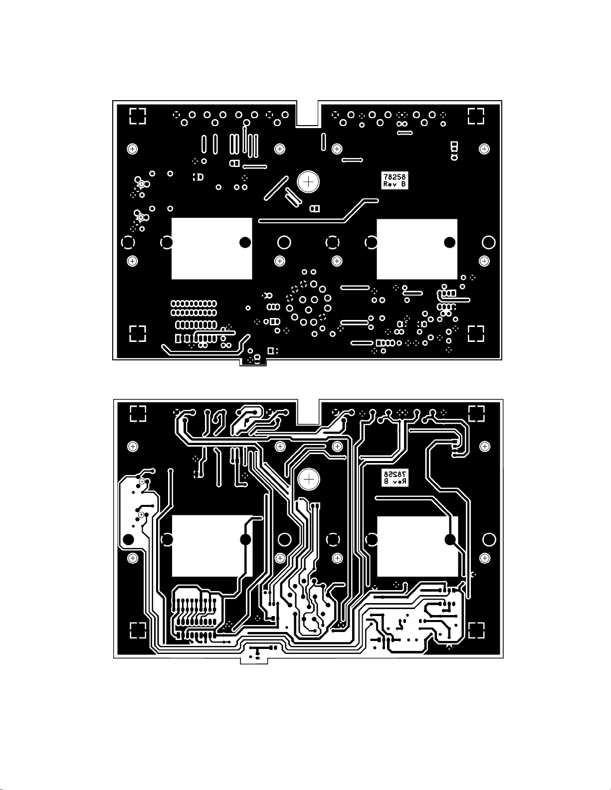
COMPONENT SIDE COPPER
R
SOLDER SIDE COPPE
FIGURE 5-14 METER/SWITCH BOARD (ASSEMBLY A12)
CIRCUIT VIEWED THROUGH BOARD FROM FRONT PANEL
5-11
Page 37
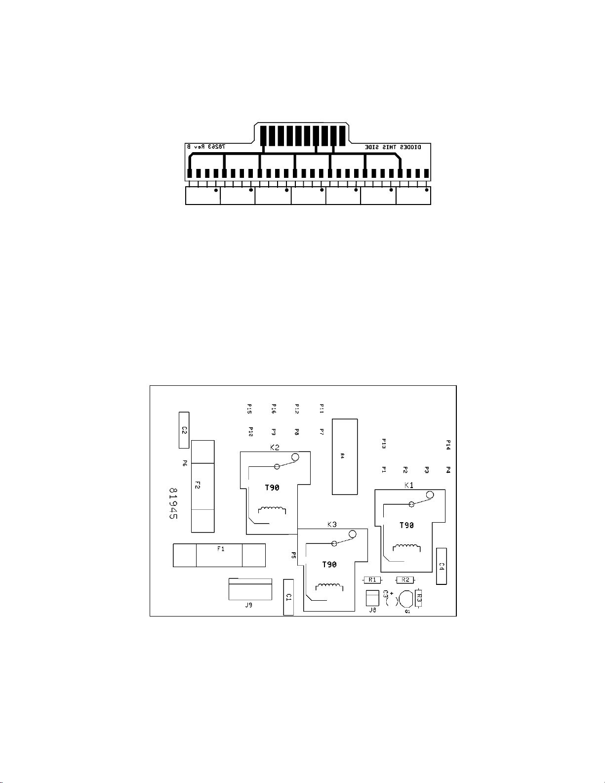
FIGURE 5-16 DISPLAY BOARD (ASSEMBLY A13) BOTTOM CIRCUIT
VIEWED THROUGH BOARD FROM TOP
1
U1 GRN U2 GRN U3 GRN U4 GRN U5 GRN U6 GRN U7 RED
5.9 AC LINE DELAY BOARD A9 (81945) This board contains the step start relays and
associated circuitry to control inrush current while the H.V. filter capacitors charge.
5-12
FIGURE 5-17 AC LINE DELAY BOARD (ASSEMBLY A9)
COMPONENT LAYOUT TOP SIDE VIEW
Page 38
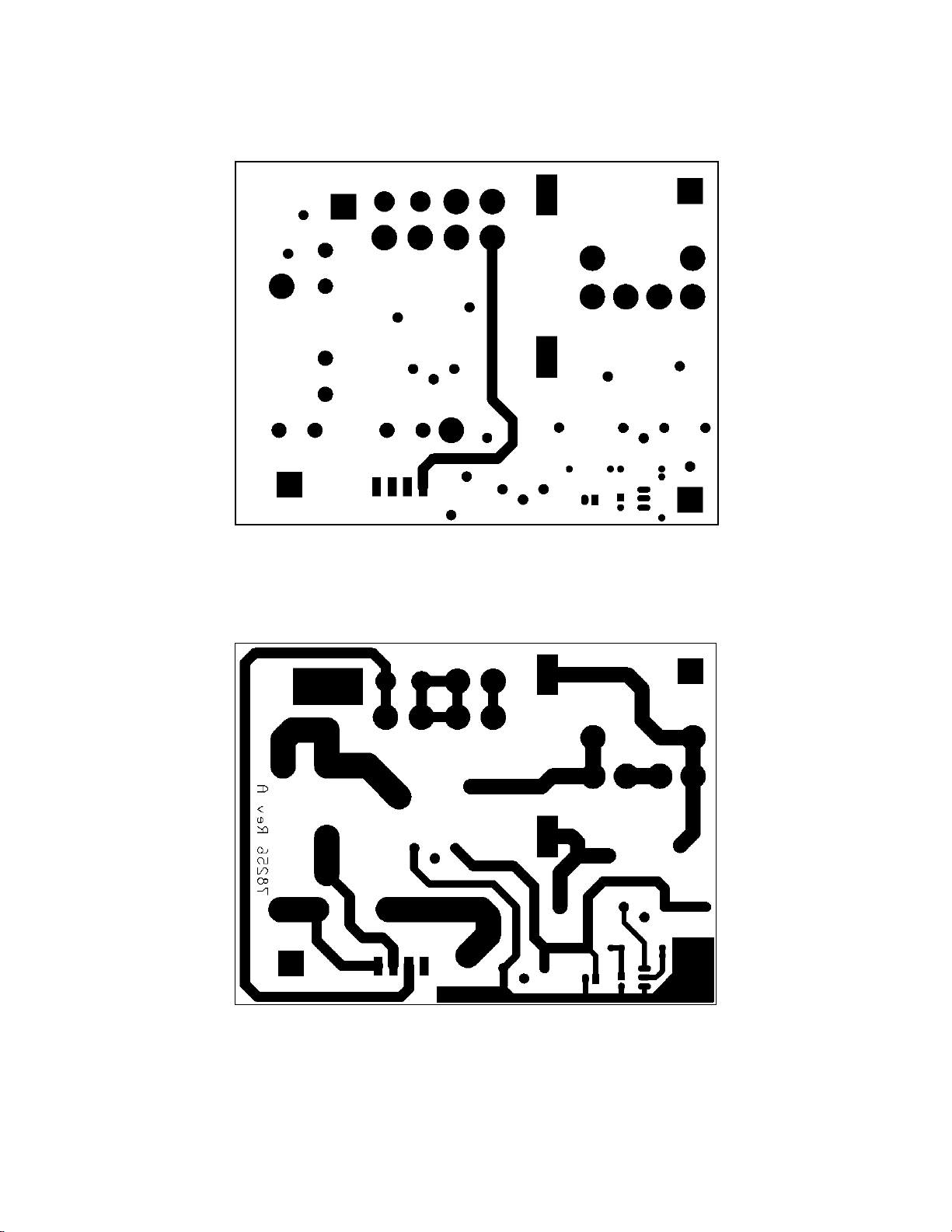
TOP COPPER
BOTTOM COPPER
FIGURE 5-18 AC LINE DELAY BOARD (ASSEMBLY A9)
CIRCUIT TRACE TOP VIEW THROUGH BOARD
5-13
Page 39
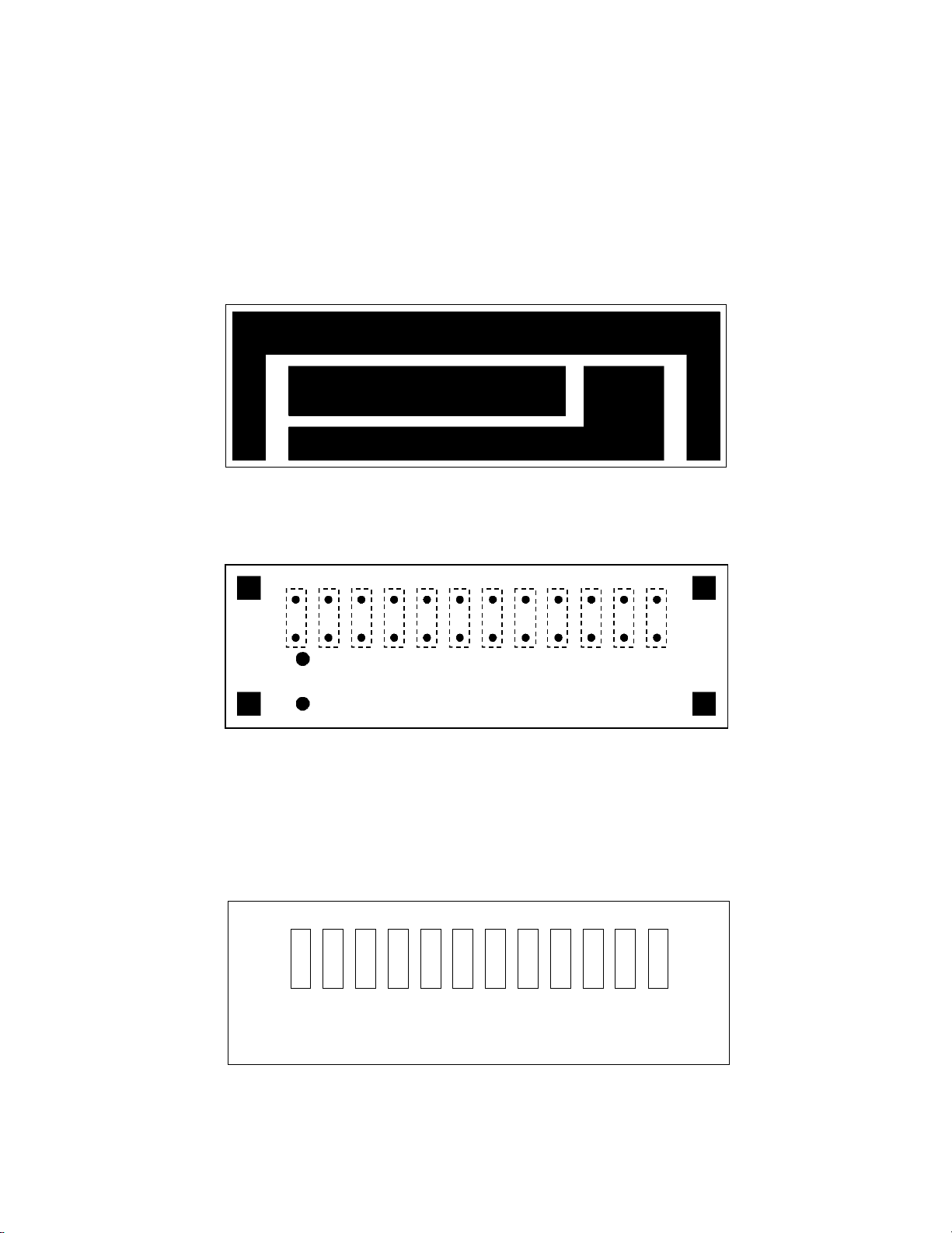
5.10 LOAD SHUNT BOARD A5 (81943) This board contains some of the extra load
A
capacitance needed for the tank circuit on the 160M band. Capacitance is paralleled
across the variable load capacitor on bandswitch positions 160A, and 160B, and 80.
FIGURE 5-19 LOAD SHUNT CAP BOARD (ASSEMBLY A5)
CIRCUIT VIEWED THROUGH BOARD FROM TOP
BOTTOM COPPER
5-14
TOP COPPER
C1 C2 C3 C4 C5 C6 C7 C8 C9 C10 C11 C12
81943 Assembled
78254 Rev
FIGURE 5-20 LOAD SHUNT CAP BOARD (ASSEMBLY A5)
COMPONENT LAYOUT TOP VIEW
Page 40
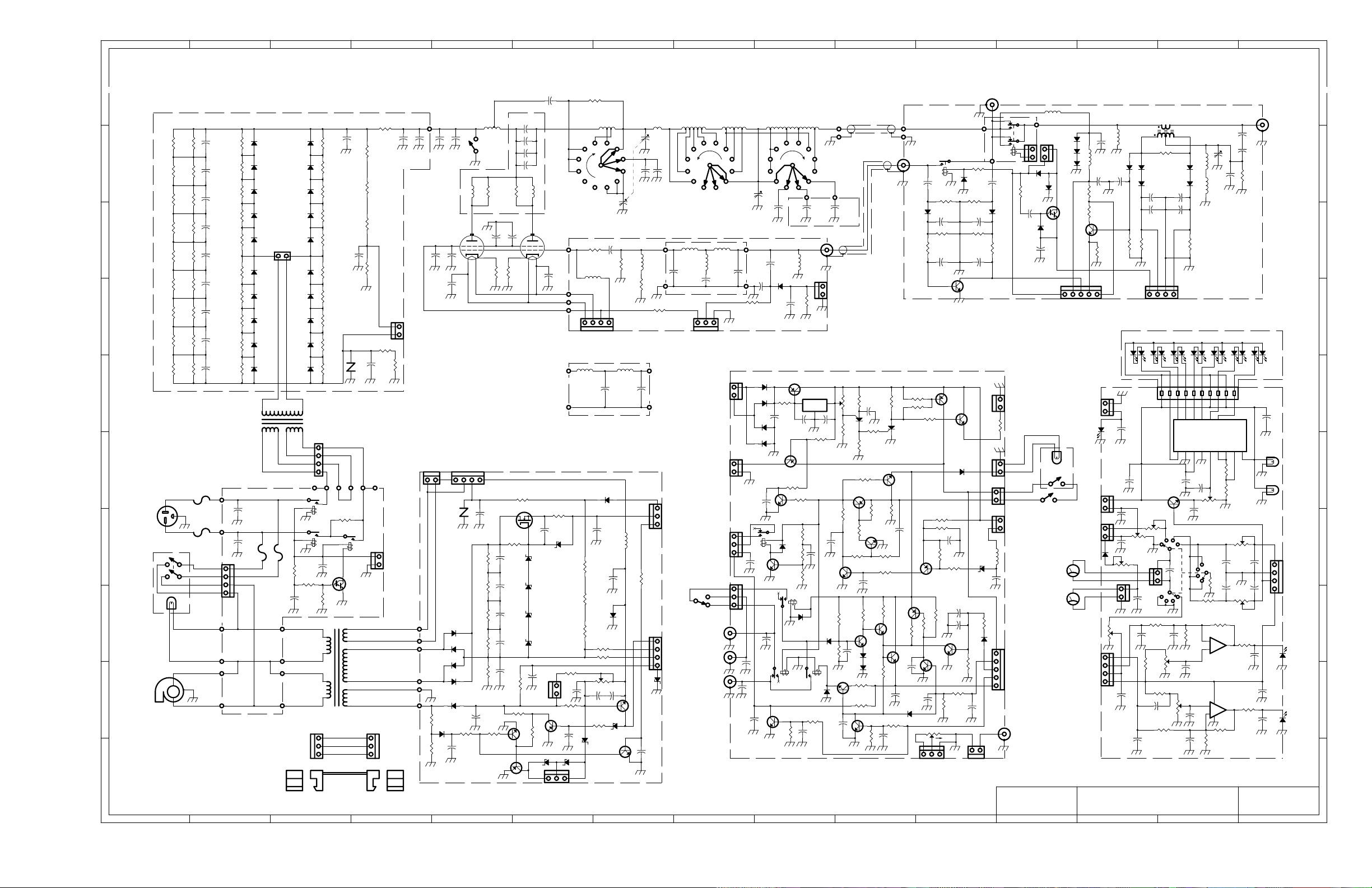
A
FIGURE 5-21 SCHEMATIC DIAGRAM MODEL 417A
5-15
B
C
D
E
F
G
H
I
J
K
L
M
N
O
RELAY BOARD
A14
81959
D3
4148
C12
C11
0.01
0.01
C17
C13
0.01
0.01
Q2
4124
Q5
MJE
371
Q7
4124
D5
4148
+
C10
10uF
R27
100
C24
1uF
+
C17
0.01
Q17
4124
R37
10K
R47
4.7K
R49
0.01
10K
C25
CCW
1
1
J15
TRANSCEIVER
SO239
P6
R16
270
R10
100K
R14
100K
12V
R22
1.5K
1
1
L1
100
uH
D9
4.7V
C8
0.1
R38
10K
D12
4148
1
J13
ALC
GND
K1
P7
C9
18pF
D8
4148
R12
10K
1
J7
1
J6
J10
J5
J11
P5
J28 J28
D4
4148
D14
4007
R17
10K
Q3
A14
C19
0.1
FILM
C18
1000uF
GND
WAIT LED
ORN
ORN
GND
OPR LIGH T
OPR +
OPR -
S2 INTLCK
DISP +12V
PLATE FAULT
+12V
RF SENSE
INPUT SENSE
RELAY SENSE
RELAY POWER
J26
ALC
L5
1mH
D11
4007
D10
4007
4007
D9
D13
4148
+
J11
RELAY POWER
OPERATE
S4
PLATE FAULT
PLATE V SAMPLE
PLATE -I SAMPLE
M1
MULTI
M2
Ip
A4
R15
10K
R8
4.7K
INPUT SENSE
RELAY SENSE
GND
WAIT LED
WAIT
DISP
+12V
+
-
-
+
GRID LED
SCRN LED
SCRN -I
-16V
D4
4148
RF SENSE
L4
15uH
C15
0.01
Q1
6517
R6
10K
+12V
A12
C14
0.01
1
J7
D1
LED
J5
J3
J4
C25
0.01
D12
4148
C16
0.01
R7
330K
1
C21
0.01
1
1
Ip
JA
1
R11
10K
T1
L1
1
1mH
C15
0.01
C4
0.01
R2210K
CAL
Is CAL
C7
0.01
C16
0.01
R1
47,2W
2.2uH
D1
D2
4148
4148
D6
D5
4148
4148
C2
C3
0.01
0.01
+
10K
R7
-16V
10K
U2
1
R6
R8
47K
Is
S1C
100K
1
C20
0.01
R17
FWD
+
C4
1uF
R2
330K
1
REV
GND
A13
U3
U4
L2L3L4L5L6L7L8
V-
L1
1
C11
C12
0.1
0.1
Q1
4124
+
C8
1uF
S1B MULTIMETER
C22
0.01
R18
100K
R20
100K
SCR
LED
C19
SET
0.01
GRID
LED
SET
R21
100K
C18
0.01
C17
0.01
C5
1uF
R4
330K
J14
U1
GRN GRN GRN GRN GRN RED RED
JP1
R23
100K
Ip FLT
R19
10K
JB
C10
0.01
C5
0.01
C24
0.01
C1
3-22pF
SWR NULL
L3
C6
270pF
L2
1mH
(molded)
SWR BOARD 81951
U5
U2 LM3914
SIG
V+
Rlo
Rhi
R15
1.5K
R14
330
R3
10K
BAR CAL
S1A
R13
2.2K
R12
4.7K
R4
1M
5
+
-
6
U1B
LM393
U1A
4
LM393
2
-
3
+
8
R10
1M
R16
100K
METER/SWITCH BOARD
U6
L9
Oref
Iref
REV CALVp CAL
R2
10K
C9
0.01
C3
0.01
R1
10K
FWD CAL
7
1
R5
1K
C13
0.01
C7
10pF
C8
10pF
R3
680
U7
DISPLAY
81952
C23
0.1
L10
MODE
DS1(M1)
DS2(M2)
METER LAMP S
C2
0.01
C1
1
0.01
D3
LED
C6
0.1
R9
1K
D2
C14
LED
0.01
81947
J16
ANTENNA
SO239
J14
REV
GND
FWD
-16V
SCREEN
GRID
10 10
R7
C15
A2 A3
HIGH VOLTAGE RECTIFIER BOARD 81944
+
R45
150K
2W
R16
150K
2W
R15
150K
2W
R14
150K
R13
150K
2W
R12
150K
2W
R11
150K
R10
150K
R9
150K
2W
C14
R17
220uF
+
C1
220uF
400V
+
C2
220uF
400V
+
C3
220uF
400V
+
C4
220uF
400V
+
C5
220uF
400V
+
C6
220uF
400V
+
C7
220uF
400V
+
C8
220uF
400V
D1
680K
P600J
0.5W
R18
D2
680K
P600J
0.5W
R19
D3
680K
P600J
0.5W
R20
D4
680K
P600J
0.5W
R21
D5
680K
P600J
0.5W
R22
680K
0.5W
R42
680K
0.5W
R23
680K
0.5W
R24
680K
0.5W
R25
680K
0.5W 0.5W
D6
P600J
D7
P600J
D8
P600J
D9
P600J
D10
P600J
J2
HV1
D20
P600J
D19
P600J
D18
P600J
D17
P600J
D16
P600J
D15
P600J
D14
P600J
D13
P600J
D12
P600J
D11
P600J
R35
680K
0.5W
R34
680K
0.5W
R33
680K
0.5W
R32
680K
0.5W
R31
680K
0.5W
R30
680K
0.5W
R29
680K
0.5W
R28
680K
0.5W
R27
680K
0.5W
R26
680K
R44
150K
2W 400V
9 9
R1
150K
2W
R2
150K
2W
R3
150K
2W 2W
8 8
R4
150K
2W
R5
150K
2W
R6
150K
7 7
2W 2W
R7
150K
2W 2W
R8
150K
2W
C13
0.1
250V
C10
1nF
6KV
150K
R39
Z1
MOV
25V
R43
10,25W
R36
1M,2W
R37
1M,2W
R38
1M,2W
R41
1.5,5W
1.5,5W
C11
0.1
250V
1
R40
3000V
C12
C9
1nF
1nF
6KV 6KV
J3
PLATE V SAMPLE
PLATE -I SAMPLE
C6
0.01
P3
C13
1nF
6KV 6KV
C10
0.01
6 6
2200V
T1
PLATE TRANSFORMER
RED RED
5 5
A9
F2
20A
AC LINE BOARD 81945
F1
20A
BLU
BLU
BLK
BLK
ORN
ORN
P16
P15
P5
C2
0.01
1KV
P6
C1
0.01
1KV
F2
F1
J22
1
P7
P9
1.5 A
1.5A
P11
P12
P8
P10
A1
WHT
P3
240VAC
4 4
GRN
BLK
S3
PWR ON/OFF
ON
3 3
BLOWER
M1
2 2
CHASSIS MOUNTED PARTS ARE ASSEMBLY .
1 1
RED
J27
YEL
BLK
BLU
1
P13
P1
P2 P3
K2
R4
10,25W
K3
R1
33K
R2
100K
+
C3
1uF
50V
ORN
BRN
WHT
BLK
T2
CABLE WIRING / LABELING CONVENTION
K1
C4
0.01
Q1
A14
R3
22K
SCREEN TRANSFORMER
1
3
Jn Jn
CABLE #n
13VAC
13VAC
P14
P4
J8
1
AC RELAY +
AC RELAY -
GRN
GRN
RED
RED
BLU
BLU
3
1
13
P6
P5
P1
P2
P3
P4
R1
15K
R2
4.7K
nn
PLATE
CHOKE
C14
1nF
L1
PLATE BOARD 81948
4CX800A
V1
55
C7*
0.01
3
*C7, C9 ARE PART OF S K- 1A S O C K E T.
FIL+
SCRNV
FILJ1
1
Z1
MOV
420V
R18
680K
R19
680K
R20
680K
D4
1A1KV
R21
D5
680K
1A1KV
D6
1A1KV
R23
150
D7
1A1KV
2W
D13
4007
-100V
C10
100uF
+
D15
4148
R5
10K
+
C9
33uF
L6
S1
HV
SHORTING
BAR
R1-5
150,2W
1
2,4,6
7
R1-3
3X12
GRIDV
J20
1
C21
0.01
IKV
R6
10K
R6-10
150,2W
C8
0.01
Q8
IRF830
12K,2W
+
+
+
+
Q2
4124
Q4
A92
C1
100uF
160V
C15
100uF
160V
C2
100uF
160V
C3
100uF
160V
C16
0.1
250V
R17
4.7K
7W
C1-4 1nF,6KV
L2
C9*
0.01
2,4,6
3
R4-6
3X12
R28
47,2W
R13
R3
100K
4CX800A
V2
1
7
C11 0.01
A10
SCREEN SUPPLY BOARD 81950
C20
0.01
D9
30V
D10
30V
D11
150V
D12
150V
C8
10uF
+
J23
GRID
CALIB
Q3
A92
R4
100K
D16
13V
J21 BIAS ADJ
25M,1W
1nF
6KV
L5
10M
S6C
REAR WAFER CENTER WAFER
BANDSWITCH S6 D RA WN IN 160A P OSIT ION . C W R OTAT ION IN DI CATED.
TUNE
160A
C1B
300pF
L4
C1A
100pF
C4
150pFC5150pF
L3
10M
A6
P4
R7-11
5X47,2W
P3
P1
P2
1
L2
0.27, 5TL10.33, 6T
10M INPUT FILTER 81954
A8
R29
10
0.5W
D18
5.1V
R27
4.7K,7W
R26
4.7K,7W
R25
4.7K,7W
R30
2.2K,0.5W
1
C11
0.01
1KV
R14
3.3K,0.5W
C13
0.1
D2
8.2V
1
C4
0.01
L2
1mH
3X 470,7W
FIL+
FIL-
GRIDV
SCRNV
C2
220pF
-65V
D19
4007
C7
0.01
1KV
L1
100uH
C14
0.1
250V
D17
4007
R22
22K
R31 4.7K
GRID LIMIT SET
R24
C18
C19
100
10uF
10uF
+
+
Q7
6517
R7
100K
D14
5.1V
D8
47V
Q1
4124
J20
R12
50
90W
R4-6
C1
100pF
+360V
L3
0.7,9T
R8
10K
1
D1
16V
C12
0.1
L2
0.33, 6TL10.33, 6T
C3
150pF
100pF
15M INPUT FILTE R 8 1 9 53
FL1
A7
R3
150K,2W
J25
1
SCRN RELAY SCRN RELAY+
BIAS ENABLE
J9
J4
GRID LED
SCRN LED
SCRN -I
-16V
C1
1
ALC POT
AC RELAY +
AC RELAY -
SCRN RELAY SCRN RELAY+
BIAS ENABLE
S5
KEY IN
KEY OUT
L2
S6B S6A
160A
LOAD
C2
800pF
L3
0.44, 7T
C2
150pF
R2
10K
INPUT MATCH BOARD 81946
J1
13VAC
13VAC
1
J8
1
C1
4.7uF
J9
1
J12
GATE
PTT
QSK
1
J17
J19
PTT
J18
C12
0.01
C15
0.01
C1
15pF
C3
100pF
C26
0.01
C13
0.01
D1
5401
D2
5401
D3
5401
D4
5401
K1
C12
400pF
C14
0.01
+
160A
D1
4148
C2
0.01
R19
47
+
C6
4700uF
Q4
MJE371
Q6
4124
Q10
W01
K2
Q18
4124
R50
10K
L1
C1-9
1350pF
Q2
MJE371
R2
1K
R16
22K
D6
4148
R15
22K
R17
22K
R1
100K
C7
1uF
R3
10K
D11
4148
10M
L1
1mH
+
K3
U1
LM7812
IN OUT
C4
33uF
R40
10K
FRONT
WAFER
C10-12
450pF
J13
1
DELAY TIME SET
GND
C2
0.1
R1
1K
+
D13
4148
R32
10K
K4
REED
D10
4148
C22
0.01
J24
RF INPUT
ALC
GND
+
C3
1uF
Q14
4124
C18
0.01
A5
CAP
PADS
81943
R42
10K
Q19
6027
R29
8.2K
R13
10K
R28
R31
10K
Q15
4124
Q3
MJE371
1K
R12
10K
Q9
4124
C19
0.01
R35
270
R9
1K
R48
10K
A11
R4
220K
R5
1K
R41
10K
Q13
4124
Q8
4124
+
+
C9
10uF
R30
2.2K
R43
10K
D7
4148
D8
4148
C5
470uF
R6
1K
R10
1K
Q21
4124
R34
10K
R7
1.5K
R11
R14
10K
R20
10K
1K
C11
10uF
R39
10K
P1
P4
J24
C10
18pF
D7
4148
R13
10K
QSK BOARD 81949
R8
1K
R21
1K
Q11
5060
12V TIMED
Q1
W01
+
Q22
5087
R46
2.2K
Q12
W01
C23
0.56
C21
0.01
C27
0.1
D14
4148
C16
0.01
J25
R23
10K
R25
2.2K
R26
10K
Q20
5087
R45
10K
R51
4.7K
Q23
4124
R52 10K
ALC POT
R11
100K
R9
100K
R24
10K
K1
REED
417A AMPLIFIER12/14/05
A
B
C
D
E
F
G
H
I
J
K
L
M
N
O
Page 41

MASTER PARTS LIST
MODEL 417A
CHASSIS MOUNTED PARTS A1
CHAPTER 6
ITEM DESCRIPTION
T1 HV TRANSFORMER
T2 LV TRANSFORMER
BLOWER CENT. BLOWER
S1 SHORTING BAR
S2 INTERLOCK SW
S3 ON-OFF SW
S4 STBY-OPR SW
S5 QSK –PTT SW
S6 BAND SW
L1, L2 TANK COIL-1
L3 TANK COIL-2
L4 10M PI COIL
L5 15/10M PLATE MATCH
L6 PLATE CHOKE
JUMPER STRAP
C1A C1B TUNE CAPACITOR
C2 LOAD CAPACITOR
C4, C5 150pF 5KV N750
C6-C11 .01uF 1KV
C12 400pF 7.5KV N3300
C13-C15 1nF 6KV
R1-R6 12 Ohm, 2W
R7 25M Ohm, 1W, 5kV
P3 AC PLUG
V1 V2 4CX800A TETRODE
V1/V2-S TUBE SOCKETS W/BYP
F1-F2 20 ABS FUSE
FUSE HOLDER
6:1 VERNIER
TUBE RETAINER
BAR KNOB
LOAD-TUNE KNOB
DIAL SKIRT
METER SW KNOB
BAIL
RT BAIL FOOT
LF BAIL FOOT
REAR FEET
HOLE PLG - MTR ADJ
TEN-TEC PART #
81859 FROM 21199
21198
38305
93690
32063
32128
32129
32130
98560 FROM 32149
85427-13
85427-11
85427-6
85427-12
85427-1
85427-14
23520
23526
23297
23013
23300
23295
30405
30742
35153
25513
27084
27038
27009
38146
38265
34058
81601
91209-1CU
80529
91178
90926
90925
42020
42044
6-1
Page 42

AC LINE BOARD A9
81945
ITEM DESCRIPTION
C1 .01uF 1KV
C2 .01uF 1KV
C3 1uF 50V
C4 .01uF 1KV
K1 RELAY SPST
K2 RELAY SPST
K3 RELAY SPST
COVER, RELAY
Q1 MPSA14
R1 33K
R2 100K
R3 22K
R4 10 25W
F1 F2 1.5 AMP MDL
INPUT MATCHING BOARD A6
81946
C1 15pF 1KV
C2 .01uF
C3 100pF
C4 .01uF 1KV
D1 1N4148
FL1/A7 15M INPUT FILTER
L1 L2 1MH
L3 COIL-TOROID, .7uH
R1 100K
R2 10K
R3 150K 2W
R4 470 7W
R5 470 7W
R6 470 7W
R7 47 OHM 2W
R8 47 OHM 2W
R9 47 OHM 2W
R10 47 OHM 2W
R11 47 OHM 2W
R12 50 OHM 90WATT
TEN-TEC PART #
23013
23013
23264
23013
32067
32067
32067
32072
25253
30155
30161
30154
30310
27018
23372
23260
23013
23385
28001
81953
21135
85427-7
30161
30150
30311
30721
30721
30721
30408
30408
30408
30408
30408
30223
6-2
Page 43

METER-SWITCH BOARD A12
81947
ITEM DESCRIPTION
C1 .01uF
C2 .01uF
C3 .01uF
C4 .01uF
C5 .01uF
C6 .1uF
C7 .01uF
C8 1uF 50V
C9 .01uF
C10 .01uF
C11 .1uF
C12 .1uF
C13 .01uF
C14 .01uF
C15 .01uF
C16 .01uF
C17 .01uF
C18 .01uF
C19 .01uF
C20 .01uF
C21 .01uF
C22 .01uF
C23 .1uF
C24 .01uF
C25 .01uF
D1 LED
D2 LED
D3 LED
D4 1N4148
M1 MULTIMETER 1mA
M2 PLATE METER 1mA
Q1 2N4124
R1 10K TRIMPOT
R2 10K TRIMPOT
R3 10K TRIMPOT
R4 1M
R5 1K
R6 10K
R7 10K
R8 47K
R9 1K
R10 1M
R11 10K TRIMPOT
TEN-TEC PART #
23260
23260
23260
23260
23260
23261
23260
23264
23260
23260
23261
23261
23260
23260
23260
23260
23260
23260
23260
23260
23260
23260
23261
23260
23260
28024
28024
28024
28001
98540
98544
25258
30038
30038
30038
30173
30138
30038
30038
30157
30138
30173
30038
6-3
Page 44

ITEM DESCRIPTION
TEN-TEC PART #
R12 4.7K
R13 2.2K
R14 330
R15 1.5K
R16 100K
R17 100K
R18 100K
R19 10K TRIMPOT
R20 100K PC ADJ
R21 100K PC ADJ
R22 10K TRIMPOT
R23 100K TRIMPOT
SW1 METER SW
U1A P/O LM393
U1B P/O LM393
U2 LM3914
PLATE BOARD A3
81948
C1 .001uF 6KV
C2 .001uF 6KV
C3 .001uF 6KV
C4 .001uF 6KV
L1 L2 PARASITIC SUP
R1-R5 150 2W
R6-R10 150 2W
30146
30142
30132
30140
30161
30161
30161
30038
30620
30620
30038
30198
98449 FROM 32050
25260
25260
25101
23295
23295
23295
23295
85427-5
30407
30407
QSK BOARD A11
81949
C1 4.7uF 35V
C2 .1uF
C3 1uF 50V
C4 33uF 16V
C5 470uF 6.3V
C6 4700uF 35V
C7 1uF 50V
C8 .1uF
C9 10uF
6-4
23310
23261
23264
23308
23567
23191
23263
23261
23266
Page 45

ITEM DESCRIPTION
TEN-TEC PART #
C10 10uF
C11 10uF
C12 .01uF
C13 .01uF
C14 .01uF
C15 .01uF
C16 .01uF
C17 .01uF
C18 .01uF
C19 .01uF
C21 .01uF
C22 .01uF
C23 .56uF
C24 1uF 50V
C25 .01uF
C26 .01uF
C27 .1uF
D1 1N5401
D2 1N5401
D3 1N5401
D4 1N5401
D5 1N4148
D6 1N4148
D7 1N4148
D8 1N4148
D9 1N750 4.7V ZENER
D10 1N4148
D11 1N4148
D12 1N4148
D13 1N4148
D14 1N4148
K1 SCRN RELAY
K2 KEY/OFF RELAY
K3 OP/STBY RELAY
K4 KEY_OUT RELAY
L1 100UH
Q1 MPSW01
Q2 MJE371
Q3 MJE371
Q4 MJE371
Q5 MJE371
Q6 2N4124
Q7 2N4124
Q8 2N4124
Q9 2N4124
Q10 MPSW01
Q11 2N5060 SCR
23266
23266
23260
23260
23260
23260
23260
23260
23260
23260
23260
23260
23331
23263
23260
23260
23261
28047
28047
28047
28047
28001
28001
28001
28001
28058
28001
28001
28001
28001
28001
32103
32120
32120
32081
21060
25023
25105
25105
25105
25105
25258
25258
25258
25258
25053
25039
6-5
Page 46

ITEM DESCRIPTION
TEN-TEC PART #
Q12 MPSW01
Q13 2N4124
Q14 2N4124
Q15 2N4124
Q17 2N4124
Q18 2N4124
Q19 2N6027 UJT
Q20 2N5087
Q21 2N4124
Q22 2N5087
Q23 2N4124
R1 1K
R2 1K
R3 10K
R4 220K
R5 1K
R6 1K
R7 1.5K
R8 1K
R9 1K
R10 1K
R11 1K
R12 10K
R13 10K
R14 10K
R15 22K
R16 22K
R17 22K
R19 47
R20 10K
R21 1K
R22 1.5K
R23 10K
R24 10K
R25 2.2K
R26 10K
R27 100
R28 1K
R29 8.2K
R30 2.2K
R31 10K
R32 10K
R34 10K
R35 270
R37 10K
25053
25258
25258
25258
25258
25258
25185
25001
25258
25001
25258
30138
30138
30150
30077
30138
30138
30140
30138
30138
30138
30138
30150
30150
30150
30154
30154
30154
30122
30150
30138
30140
30150
30150
30142
30150
30126
30138
30149
30142
30150
30150
30150
30131
30150
6-6
Page 47

ITEM DESCRIPTION
TEN-TEC PART #
R38 10K
R39 10K
R40 10K
R41 10K
R42 10K TRIMPOT
R43 10K
R45 10K
R46 2.2K
R47 4.7K
R48 10K
R49 10K
R50 10K
R51 4.7K
R52 10K ALC POT
U1 LM7812
SCREEN SUPPLY BOARD A10
81950
C1 100uF 160V
C2 100uF 160V
C3 100uF 160V
C7 .01uF 1KV
C8 10uF 25V
C9 33uF 16V
C10 100uF 160V
C11 10uF 50V
C12 .1uF
C13 .1uF
C14 .1uF 250V
C15 100uF 160V
C16 .1uF 250V
C17 .01uF
C18 10uF 25V
C19 10uF 25V
C20 .01uF
C21 .01uF 1KV
D1 1N5246 16V ZENER
D2 1N756 8.2V ZENER
D4 1A 1KV
D5 1A 1KV
D6 1A 1KV
30150
30150
30150
30150
30619
30150
30150
30142
30146
30150
30150
30150
30146
30267
25232
23516
23516
23516
23013
23266
23308
23516
23266
23261
23261
23006
23516
23006
23260
23266
23266
23260
23013
28141
28019
28122
28122
28122
6-7
Page 48

ITEM DESCRIPTION
TEN-TEC PART #
D7 1A 1KV
D8 1N5368 47V ZENER
D9 1N5363 30V ZENER
D10 1N5363 30V ZENER
D11 1N5383 150V ZENER
D12 1N5383 150V ZENER
D13 1N4007
D14 1N751 5.1V ZENER
D15 1N4148
D16 1N964 13V ZENER
L1 100uH 100mA
Q1 2N4124
Q2 2N4124
Q3 MPSA92
Q4 MPSA92
Q7 2N6517
Q8 IRF830
R1 15K
R2 4.7K
R3 100K
R4 100K
R5 10K
R6 10K
R7 100K
R8 10K
R13 12K 2W
R14 3.3K .5W
R17 4.7K 7W
R18 680K .5W
R19 680K .5W
R20 680K .5W
R21 680K .5W
R22 22K
R23 150 2W
R24 100 OHM TRIMPOT
R25 4.7K 7W
R26 4.7K 7W
R27 4.7K 7W
R28 47 OHM 2W
R29 10 OHM .5W
Z1 MOV
28122
28136
28134
28134
28135
28135
28043
28041
28001
28010
21060
25258
25258
25107
25107
25393
25514
30076
30146
30161
30161
30150
30150
30161
30150
30324
30027
30719
30066
30066
30066
30066
30154
30407
30617
30719
30719
30719
30408
30022
30718
6-8
Page 49

SWR BOARD A4
81951
ITEM DESCRIPTION
C1 3-22pF
C2 .01uF
C3 .01uF
C4 1uF 50V
C5 1uF 50V
C6 330pF
C7 10pF
C8 10pF
C9 18pF
C10 18pF
C11 .01uF
C12 .01uF
C13 .01uF
C14 .01uF
C15 .01uF
C16 .01uF
C17 .01uF
C18 1000uF 35V
C19 .1uF FILM
D1 1N4148
D2 1N4148
D3 1N4148
D4 1N4148
D5 1N4148
D6 1N4148
D7 1N4148
D8 1N4148
D9 1N4007
D10 1N4007
D11 1N4007
D12 1N4148
D13 1N4148
D14 1N4007
K1 REED RELAY
L1 1mH RFC
L2 1mH MOLDED
L3 2.2uH
L4 15uH
L5 1mH RFC
Q1 2N6517
Q2 2N4124
Q3 MPSA14
R1 47 OHM 2W
R2 330K
TEN-TEC PART #
23169
23260
23260
23264
23264
23397
23371
23371
23373
23373
23260
23260
23260
23260
23260
23260
23260
23200
23328
28001
28001
28001
28001
28001
28001
28001
28001
28043
28043
28043
28001
28001
28043
32049
21135
21007
21116
21126
21135
25393
25258
25253
30408
30302
6-9
Page 50

ITEM DESCRIPTION
TEN-TEC PART #
R3 680
R4 330K
R6 10K
R7 330K
R8 4.7K
R9 100K
R10 100K
R11 100K
R13 10K
R14 100K
R15 10K
R16 270
R17 10K
T1 SWR XFMR
RELAY BOARD A14
81959
K1 OUTPUT RELAY
RELAY PCB
30136
30302
30150
30302
30146
30161
30161
30161
30150
30161
30150
30131
30150
85380-15
32101
78270
LOAD CAP SHUNT BOARD A5
81943
C1 – C9 150pF 3KV COG
C10 – C12 150pF 3KV COG
HV POWER SUPPLY BOARD A2
81944
C1–8, C14 220MFD 400V EL
C9, C12-14 .001MFD 6KV CER
C11 .1MFD 250V FILM
D1-D20 RECTIFIER GI P600J
J2 AMP MATE-N-LOCK
R1-16, R39,
R44, R45 150K 2W
R17-25,R42 680K 3/4W
R36-38 1M 3W IRC GS3
R40, R41 1.5 OHM 5W WW
R43 10 OHM 25W WW
Z1 VARISTOR, V39ZA1
23542
23542
23409
23295
23006
28098
35307
30311
30066
30533
30411
30310
30329
6-10
 Loading...