

Page 1
18 June 2004 RadCom www.rsgb.org
Reviewed by Peter Hart, G3SJX
The Willows, Paice Lane,
Medstead, Alton, Hants GU34 5PR
REVIEW
Ten-Tec Orion HF
T
en-Tec has acquired a reputation
for making radios with a good RF
performance and catering
particularly for the needs of the CW
operator. Over the years, their topend flagship models have excelled,
particularly when it comes to
handling the challenging competitive
environment of hectic contest or DX
working. The Corsair and Omni
series, culminating in the Omni-VI,
were developed to provide an
impeccable adjacent channel
performance at the expense of
broadband coverage, whereas other
manufacturers had taken the
broadband ‘bells and whistles’
approach.
Ten-Tec has now launched a new
top-end radio pushing the state of
the art to a higher plateau and
combining the very best of both
narrow band and broadband
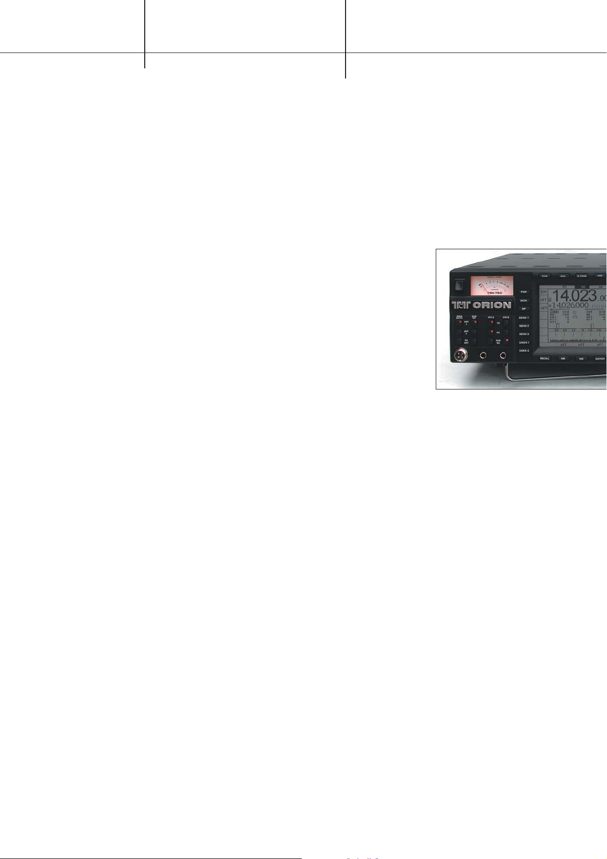
approaches. The new Orion is
targeted as a home station radio with
a 100W transmitter and two
independent and fully-featured
receivers. One receiver covers
amateur bands only and is optimised
for highest performance whereas the
second receiver provides general
coverage operation.
Although the Orion has been
available in the USA since early in
2003, it has only recently received
CE approval for sales within Europe.
It is available in two versions, model
565 without auto ATU and model
565AT with internal auto ATU fitted.
BASIC FUNCTIONS
The Orion is a large table-top sized
12V operated radio measuring 432W
x 133H x 476Dmm and weighs about
9.2kg. Although, from the amount of
space inside the cabinet, the radio
could have been made significantly
smaller, the larger format makes for
an easy to use and clearly laid out
panel with spacious buttons and
good-sized controls. The main
receiver and transmitter tune the
160m to 10m amateur bands
(including the new 60m allocation)
with a little overlap. The second or
sub receiver tunes from 100kHz to
30MHz, although the sensitivity
drops sharply below 1MHz making
the receiver unusable at the lower
frequencies. Modes covered are USB,
LSB, CW (upper and lower sideband),
AM, FM and FSK.
In common with the Jupiter
transceiver [see review in January
2004 RadCom - Ed], the firmware in
the Orion may be upgraded from the
Ten-Tec website so the transceiver
need never be out of date. To support
this approach, all controls on the
front panel are software addressable,
either push buttons or rotary
encoders. An array of 27 buttons
around the LCD panel provides a
high level of customisation and
adjustment to suit different operating
conditions and preferences. In some
cases these are menu selectable and
in other cases dependant on mode or
other context but all are easy to
access; never more than a couple of
button presses are needed. Up to five
user profiles may be stored and
recalled at the press of a button.
The rear panel carries an extensive
array of interface connectors. There
are two main antenna sockets and a
receive-only antenna socket and
these may be freely assigned to any
receiver / transmitter combination
and stored against the band selection
settings. There is a transverter
output (+15dBm) with control, audio
line output, auxiliary interfacing to
PC sound cards and for FSK keying,
RS-232 serial data port for computer
control and firmware upgrading and
extensive support for both QSK and
non-QSK linears. Control for two
separate linears is provided, one
associated with each antenna socket,
and there are two separate band data
output controllers. Linear control is
very comprehensive, supporting
hardware QSK keying loops and user
control of sequencing delays and
drop-back times.
The Orion transceiver is provided
with various plugs and leads
including a full accessory jack lead
and a microphone plug, although the
microphone is an extra. The radio
accommodates most microphone
types including electret and Ten-Tec
supplies hand and desk models. The
radio is shipped with a 60-page
operator’s manual which covers the
set-up and operation of the controls.
Circuit schematics are freely
downloadable from the Ten-Tec
technical support website together
with various application notes,
firmware upgrades and a software
programmer’s guide.
RADIO DESIGN
Both receivers in the Orion use a
triple superhet architecture. The
main receiver covering just the
amateur bands has IFs of 9MHz,
450kHz and 14kHz. Although the
main channel selectivity is achieved
by DSP at the 14kHz IF, a range of
narrow roofing filters is selectable
immediately following the first mixer,
which ensures the very best close-in
dynamic range is achieved. Narrow
preselection filters are used in the
front end, a separate filter for each
band, a switchable bipolar RF
amplifier and a quad of four JFETs
for the first mixer. The main receiver’s
synthesiser uses a PLL operating in
the 400 - 500MHz region with a DDS
driven reference. This is then divided
down to the required first mixer local
oscillator frequency using high-speed
dividers. This technique ensures very
low close-in phase noise.
The Sub receiver has IFs of 45MHz,
455kHz and 14kHz and uses
circuitry similar to the Jupiter. The
receiver front end uses half octave
switchable bandpass filters, a pushpull FET first mixer and three
parallel FETs in the RF amplifier. The
RF amplifier is in circuit all the time
but there is a switchable attenuator
for very strong signal situations.
Conversion to the second and third
IFs uses diode balanced mixers. The
local oscillator drive for the first
mixer is derived from a single loop
PLL tuning in 2.5kHz steps. The
smaller tuning step sizes are
Page 2
19www.rsgb.org RadCom June 2004
REVIEW
transceiver
“Truly awesome performance” says Peter Hart. Find out what precisely he
was enthusing about in this, the first UK full technical review of Ten-Tec’s
long-awaiting new flagship model, the Orion.
accommodated within the DSP.
Hence the signals within the IFs
move by up to 2.5kHz.
Both receivers use identical DSP IF
and back-end circuitry with identical
features. 24-bit A/D converters are
used to drive the two 32-bit floating
point DSPs. AGC is applied mainly
within the DSP but a separate
second loop around the first and
second IFs comes into operation with
strong signals. A built-in TCXO
reference ensures good frequency
accuracy and stability.
The radio is constructed around a
sheet aluminium frame with four
compartments top and bottom. The
PA unit on the rear panel is fitted
with a heatsink but no fan. The radio
runs sufficiently cool under normal
circumstances without a fan. The 4in
high quality speaker in the case top is
a much larger and more substantial
unit than is fitted in most radios.
DUAL RECEIVERS
The radio is fitted with two VFOs
which may be assigned to either
receiver or transmitter in any
combination. The two 50mm
diameter tuning knobs tune in a
variety of step sizes from 1Hz to
100kHz at 62 or 250Hz steps per
knob revolution and a button press
increases the step size normally by a
factor of 10 for rapid band
navigation. Individual buttons select
the amateur bands, but only for VFO
A. Changing bands for VFO B is less
convenient, involving swapping back
and forth between A and B: this must
surely be something for Ten-Tec to
address in a future software upgrade.
The band buttons scroll through four
separate settings per band which can
be useful if you operate regularly on
several different modes.
Both VFO frequencies are
continuously displayed to 1Hz
resolution and both can be entered
directly from the band buttons which
double as a numeric keypad. 200
simple memories store frequency and
mode associated with either of the
VFOs and are easy to scroll and
select. The main receiver is fitted
with a conventional analogue Smeter which indicates power on
transmit but the Sub receiver is only
provided with a small uncalibrated
bargraph on the LCD panel.
Most of the receiver functions can
be set independently for the two
receivers. This includes all the
bandwidth and noise reduction
facilities, RIT / XIT, RF gain,
switchable input attenuator, squelch
and AGC. The AGC has three preset
settings of fast, medium and slow
and a fully programmable setting. In
all cases the decay rate, hang time
and threshold level are all adjustable.
The threshold level is in effect an IF
gain control and can be set as low as
0.37µV. This shows potentially a very
high gain in the signal path,
sufficient for AGC to act on noise
alone. The manual goes into great
detail about the importance of setting
the AGC parameters to enhance
signal readability under extreme
conditions. It is true that carefully
tweaking the AGC parameters can
noticeably enhance readability but I
am sceptical about the reasons for
this. It seems to me that the AGC can
be made to introduce an element of
non-linear signal slicing.
The two receivers have separate
audio gain controls and the audio
outputs can be routed in a number of
ways, either combined or kept
separate to headphone or auxiliary
outputs. One interesting feature is
the binaural panoramic stereo feature
when used with stereo headphones.
This can be used with either receiver
and helps in a CW pileup by
presenting a spatial separation of
signals within the audio passband.
Diversity reception is also possible by
setting the two receivers on the same
frequency, eg using a common VFO,
and having separate antennas for the
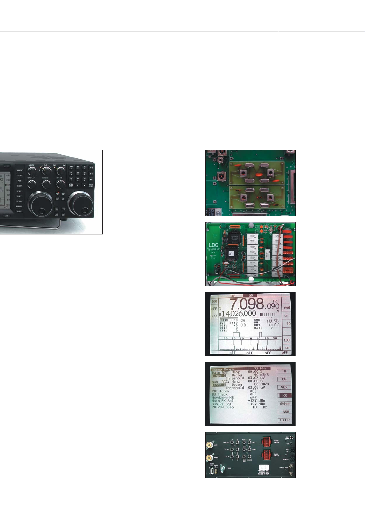
The Orion’s IF roofing
filters.
The LDG automatic
ATU board.
The LCD panel
showing the spectrum
display.
Orion LCD panel
showing the receiver
menu.
A plethora of sockets
on the rear panel.
Page 3
20 June 2004 RadCom www.rsgb.org
REVIEW
selection of roofing filters at the
9MHz IF and careful use of these
filters is key to achieving the very
best in adjacent channel
performance. 20, 6, 2.4 and 1kHz
bandwidth filters are provided as
standard but additional filters of
1.8kHz, 500Hz and 250Hz bandwidth
are available as options. All filters
can be fitted at the same time and
may be selected manually or
automatically according to the
setting of the bandwidth control.
OTHER GOODIES
Transmit features include variable
output power (5 - 100W), VOX and a
speech processor. The transmit filter
bandwidth is adjustable from 900 to
3900Hz as well as for equalisation
and low frequency roll off allowing
for different microphone
characteristics, hi-fi audio, DX
punch etc. On CW the rise and fall
characteristic of the keying envelope
is adjustable and a keyer is built in
with adjustable weighting and speed
range of 10 to 60WPM. Three
memory stores are provided for both
CW and voice modes, easy to access
via dedicated front panel buttons.
The CW stores operate only in
conjunction with the built-in keyer
and seem to hold quite long
messages but the manual does not
cover their capacity. Two of the voice
stores hold only 4.54 seconds
maximum of audio and the third
28.1 seconds but this third store is
not saved on power down.
The Orion also provides a spectrum
sweep showing signals up to ±36kHz
on either side of the main receiver
frequency. This is displayed on the
lower part of the LCD and unlike
other implementations of this feature
it is continuous and does not
interrupt the operation of the receiver.
The optional tuner fitted into the
Orion, which can be retrofitted at a
later date, is an LDG design using an
LC ladder network with latching
relays and with a particularly wide
impedance matching range of 6 to
800Ω (up to 10:1 VSWR). There are
no frequency stores so changing
bands requires a retune but this only
takes a second or two.
MEASUREMENTS
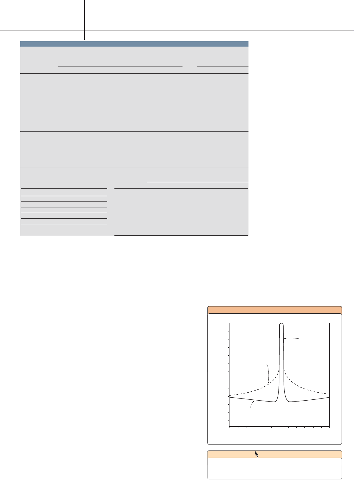
Measurements shown in the table
were made with the review radio
powered from a 13.8V supply and in
most cases with the receiver
bandwidth set to 2400Hz. Close-in
dynamic range measurements were
made with a 500Hz receive
bandwidth. Receiver measurements
relate to the main receiver unless
sub-receiver is stated.
The measured figures for third
order intercept and dynamic range of
the main receiver are very good but
lower than the Orion published
specification. The sub-receiver,
however, has a rather better
performance than the specification.
Intermodulation within the test
equipment is often the limitation in
measuring the dynamic range of high
performance radios. My
measurement set-up has been
carefully evaluated in this area and
is capable of measuring receivers to
at least +45dBm third order intercept
so I have a good degree of confidence
in the accuracy of the dynamic range
results. The close-in results with the
WEB SEARCH
Ten-Tec www.tentec.com
Ten-Tec technical support www.rfsquared.com
Ten-Tec Direct (UK) www.aoruk.com/tentec
receivers. However, the effectiveness
was marred by a slow beat (about
1Hz) when both receivers were set to
the same frequency.
FILTERS
Two DSP circuits provide identical
and separately controllable filtering
and noise reduction facilities for the
two receivers. A front panel rotary
control allows the channel bandwidth
to be set from 100Hz to 6kHz in 10Hz
steps. The upper and lower passband
edges can also be individually set
and passband tuning allows the
entire passband to be moved up or
down in frequency.
Two notch filters are provided. A
manual notch with adjustable centre
frequency and width is particularly
effective and deep. An auto-notch for
voice modes will track and notch out
multiple carriers and is also very
effective. Both notches operate at IF
up-front of the DSP AGC circuitry
and prevent the receiver AGC being
captured by strong carriers.
Adjustable DSP noise reduction is
also provided and this can be effective
in lowering background noise but
does impart a synthetic sound to the
audio. Adjustable DSP noise blanking
is also included and for the main
receiver only an additional hardware
noise blanker of the traditional type
operating at the 9MHz IF.
Adjustable audio equalisation is
also provided for both receivers and
transmitter. This can tailor the audio
response by boosting or cutting the
bass and treble frequencies.
The main receiver is fitted with a
TEN-TEC ORION MEASURED PERFORMANCE
RECEIVER MEASUREMENTS
SENSITIVITY SSB 10dBs+n:n INPUT FOR S9
FREQUENCY PREAMP IN PREAMP OUT SUB RX PREAMP IN PREAMP OUT
1.8MHz 0.35µV (-116dBm) 0.90µV (-108dBm) 0.70µV (-110dBm) 25µV 100µV
3.5MHz 0.28µV (-118dBm) 0.70µV (-110dBm) 0.40µV (-115dBm) 18µV 80µV
5.4MHz 0.25µV (-119dBm) 0.70µV (-110dBm) 0.45µV (-114dBm) 20µV 80µV
7MHz 0.32µV (-117dBm) 0.90µV (-108dBm) 0.35µV (-116dBm) 20µV 90µV
10MHz 0.35µV (-116dBm) 0.90µV (-108dBm) 0.45µV (-114dBm) 22µV 90µV
14MHz 0.28µV (-118dBm) 0.70µV (-110dBm) 0.40µV (-115dBm) 20µV 90µV
18MHz 0.32µV (-117dBm) 0.90µV (-108dBm) 0.45µV (-114dBm) 25µV 100µV
21MHz 0.40µV (-115dBm) 1.3µV (-105dBm) 0.45µV (-114dBm) 32µV 125µV
24MHz 0.50µV (-113dBm) 1.6µV (-103dBm) 0.50µV (-113dBm) 28µV 125µV
28MHz 0.50µV (-113dBm) 1.8µV (-102dBm) 0.45µV (-114dBm) 22µV 100µV
AM sensitivity (28MHz): 3.5µV for 10dBs+n:n at 30% mod depth
FM sensitivity (28MHz): 1.8µV for 12dB SINAD 3kHz pk deviation
AGC attack time: 2 - 3ms
AGC decay time: 250ms (fast), 500ms (med), 1.5s (slow) + variable
Max audio at 10% distortion: 2.0W into 4Ω
Inband intermodulation products: -35dB to -50dB
S-READING INPUT LEVEL SSB
(7MHz) PREAMP IN PREAMP OUT
S3 0.8µV 3.2µV
S5 2.2µV 10µV
S7 7.0µV 28µV
S9 20µV 90µV
S9+20 125µV 560µV
S9+40 1.4mV 5.6mV
Response (dB) single tone dynamic range
0
-10
-20
-30
-40
-50
-60
-70
-80
-90
-100
-110
-120
-30 -25 -20 -15 -10 -5 0 +5 +10 +15 +20 +25 +30
Frequency offset (KHz)
Sub RX skirts
due to lo
phase noise
Main RX skirts
due to lo
phase noise
Main filter
response
FIG 1
© RADCOM 169
BANDWIDTH
IF BANDWIDTH
SET TO -6dB -60dB -70dB -80dB
6000Hz 5236Hz 6322Hz 6363Hz 8491Hz
4000Hz 3974Hz 4362Hz see text see text
2400Hz 2364Hz 2746Hz 2773Hz 3023Hz
1800Hz 1766Hz 2151Hz 2545Hz 2640Hz
1000Hz 965Hz 1338Hz 1365Hz 1403Hz
500Hz 444Hz 843Hz 1162Hz 1237Hz
250Hz 225Hz 682Hz 883Hz 1281Hz
100Hz 131Hz 623Hz 1262Hz 1337Hz
Page 4

MAIN RX SUB RX
RECIPROCAL RECIPROCAL
MIXING BLOCKING BLOCKING MIXING
FREQUENCY FOR 3dB PREAMP PREAMP FOR 3dB
OFFSET NOISE IN OUT NOISE BLOCKING
2kHz 97dB -18dBm -6dBm not meas -24dBm
3kHz 97dB -9dBm >0dBm 65dB -24dBm
5kHz 96dB >0dBm >0dBm 72dB -24dBm
10kHz 95dB >0dBm >0dBm 77dB -13dBm
15kHz 94dB >0dBm >0dBm 81dB -11dBm
20kHz 93dB >0dBm >0dBm 83dB -4dBm
30kHz 90dB >0dBm >0dBm 87dB 0dBm
50kHz 88dB >0dBm >0dBm 92dB 0dBm
100kHz 96dB >0dBm >0dBm 98dB 0dBm
200kHz 104dB >0dBm >0dBm 104dB 0dBm
TRANSMITTER MEASUREMENTS
CW
INTERMODULATION
POWER
PRODUCTS
FREQUENCY OUTPUT HARMONICS 3rd order 5th order
1.8MHz 104W -64dB -40dB -48dB
3.5MHz 105W -64dB -40dB -44dB
5.4MHz 100W -64dB -38dB -42dB
7MHz 101W -56dB -36dB -42dB
10MHz 102W -60dB -38dB -42dB
14MHz 102W -65dB -34dB -40dB
18MHz 103W -52dB -30dB -44dB
21MHz 103W -60dB -22dB -38dB
24MHz 104W -66dB -22dB -36dB
28MHz 105W -60dB -26dB -41dB
Two-tone transmitter intermodulation product levels are quoted with
respect to PEP.
Carrier suppression: 35dB approx
Sideband suppression: >80dB @ 1kHz
Transmitter AF distortion: 2%
Microphone input sensitivity: 15mV
FM deviation: 5kHz
SSB data T/R switch speed: mute-TX 26ms,TX-mute 10ms, mute-RX 36ms,
RX-mute 14ms
NOTE: All signal input voltages given as PD across antenna terminal. Unless
stated otherwise, all measurements made on USB, preamp switched out,
2400Hz bandwidth, 6kHz roofing filter and with a 13.5V supply.
21www.rsgb.org RadCom June 2004
REVIEW
narrower roofing filters are very
impressive indeed, results with the
2.4kHz filter being significantly better
than with the 1kHz filter.
The reciprocal mixing results are
very interesting (see Fig1). At 50kHz
offset the results for the main receiver
are uninspiring and indeed somewhat
bettered by the sub-receiver. However,
the performance improves markedly
closer to the carrier and at 2kHz offset surpasses any other radio measured previously, with the possible
exception of the Ten-Tec Corsair.
These results equate to an oscillator
phase noise of -131dBC/Hz at 2kHz
offset, but still a little short of the Orion
published specification of -136dBC/Hz.
The sub-receiver reciprocal mixing
results are rather mediocre for a high
performance radio and identical to
the Jupiter results.
The very low phase noise in the
main receiver made it possible to
measure 80dB down the IF filter
skirts with excellent results. Filter
bandwidths below about 300Hz
started to exhibit wider skirts and
ripples in the stopband which limited
their ultimate performance. A weak
spurious signal limited
measurements of the higher
bandwidth filters. Rejection of IFs
and images was better than 75dB for
the main receiver but only better
than 60dB for the sub receiver. The
main receiver exhibited a spurious
response 6KHz off tune about 60dB
down but only on SSB modes and
only with the 6kHz roofing filter
selected. If this proves a problem,
select a different roofing filter.
The blocking results shown in the
table were measured with the 6kHz
roofing filter. With the 2.4 and 1kHz
filters it is possible to get even closer
to the carrier before any
desensitisation occurs. With the
1kHz filter, measurements showed
that it was possible to copy an S1
signal with an interfering signal
90dB greater only 500Hz away. This
is truly awesome performance.
Transmit SSB intermodulation
products were generally quite
reasonable but were degraded by the
speech processor. CW keying had
well-shaped edges but exhibited
some character shortening and delay
only of real significance at high
keying speeds. The auto ATU
matched well and exhibited very low
loss of only 1 - 2W at the 100W level.
Occasionally a second attempt was
needed as the first try gave an
erroneous match. The front panel
power meter was rather inaccurate at
mid range, reading significantly on
the high side.
ON THE AIR
It takes a little time to get the best
out of the Orion and become fully
acquainted and at home with all its
facets. However, as you use the
radio, understand its philosophy and
tweak its many adjustable features to
match best your operating style you
INTERMODULATION
(50kHz Tone Spacing) 2400Hz bandwidth USB
PREAMP IN PREAMP OUT SUB RX
3rd 2 tone 3rd 2 tone 3rd 2 tone
order dynamic order dynamic order dynamic
FREQUENCY intercept range intercept range intercept range
1.8MHz +9dBm 90dB +16.5dBm 90dB +14dB 89dB
3.5MHz +9.5dBm 92dB +20.5dBm 94dB +12.5dB 92dB
7MHz +9dBm 91dB +19.5dBm 92dB +14dB 93dB
14MHz +9dBm 91dB +20dBm 93dB +18dB 95dB
21MHz +11dBm 91dB +22.5dBm 92dB +18dB 95dB
28MHz +8dBm 87dB +20dBm 88dB +7.5dB 88dB
CLOSE-IN TWO TONE DYNAMIC RANGE
ON 7MHz BAND 500Hz bandwidth CW
FREQUENCY SUB
MAIN RX ROOFING FILTER BANDWIDTH
SPACING RX 20kHz 6kHz 2.4kHz 1kHz
1kHz not meas 78dB 79dB 83dB 77dB
2kHz not meas 79dB 83dB 89dB 83dB
3kHz 70dB 78dB 89dB 92dB 86dB
4kHz 72dB 80dB 88dB 94dB 89dB
5kHz 74dB 80dB 89dB 94dB 91dB
7kHz 77dB 78dB 90dB 94dB 93dB
10kHz 82dB 83dB 90dB 94dB 93dB
15kHz 90dB 89dB 91dB 94dB 93dB
20kHz 92dB 92dB 91dB 94dB 93dB
25kHz 92dB 94dB 93dB 93dB 93dB
30kHz 92dB 94dB 94dB 93dB 93dB
will find that the radio grows on you
more and more. The RF performance
is really excellent and unsurpassed
in crowded band conditions. The
ease of varying the bandwidth is a
real boon, the quality of the filters,
notches and audio is excellent and
similarly the AM broadcast
performance. However, being able to
receive very close to strong stations
is only possible if the strong station
itself has a clean signal. In a
transceiver, the phase noise
characteristic of the transmitter
largely mirrors that of the receiver
and unless the strong signal is also
an Orion, the strong signal is likely
to be the limiting factor.
Audio quality reports were
excellent. My first QSO with the
Orion was with a VK2 station who
immediately gave an unsolicited
report of excellent audio quality. CW
also generally performed well both
on the internal and external keyers.
The receiver QSK drop back delay
and the linear drop back delay are
totally separate adjustments. I had
some difficulty with my non-QSK
linear achieving a suitable balance
between the two. On CW you do not
want the linear dropping back to
receive between words but on SSB
when you release the PTT you want
the linear to drop back to receive
immediately. The linear drop back
delay is applied to all modes but on
CW should really only take effect
after the receiver delay has finished.
(A possible candidate for a software
update maybe?)
The control ergonomics are
generally very good. One minor
comment, however, is that rapid
frequency navigation is generally
better implemented on many
Japanese radios. Some roughness
on fast tuning was resolved when I
upgraded the firmware from version
1.367 to version 1.369. The upgrade
file from the website was 877kB
which installed the Flash Update
Utility on my PC. Connecting the
radio to the PC COM port then
installed the upgraded code in about
five minutes.
CONCLUSIONS
The Orion lives up to its claim as a
high performance radio with
exceptional close-in dynamic range.
It is likely to appeal particularly to
the serious and technically-minded
DX chaser or contest operator or
someone who desires the very best
in terms of performance. With its
large format panel, clearly laid out
controls, well-implemented features
and internet upgradeable software it
is a truly excellent radio.
The Orion is available in the UK
from Ten-Tec Direct, 4E East Mill,
Belper, Derbyshire DE56 2UA; tel:
01773 880788, with a list price of
£2499, or £2799 if fitted with the
auto antenna tuner. My thanks to
Ten-Tec Direct for the loan of the
review radio. ♦
 Loading...