

Page 1

TEN-TEC ARGONAUT VI MODEL 539 QUICK START GUIDE
Connect a 13.8 volt power supply via the cable provided.
Connect the red wire to the positive terminal of the power supply
Connect the black wire to negative terminal of the power supply
Connect the power cable to the mate-n-lock connection on the rear of the Argonaut VI.
Connect a 50-Ohm antenna to the antenna connection on the rear of the Argonaut VI with a PL259 and
50 ohm coax cable.
SSB
Plug a compatible microphone into the microphone jack on the front of the Argonaut VI
Turn on the Argonaut VI via the power switch (1) on the front of the Argonaut VI
Switch the three position switch to the M / center position, and then press the MOD button (10)
repeatedly to select either USB or LSB
Find a clear frequency by tuning the main tuning knob (6).
Switch the three position switch to the B / bottom position, and then press the USR button (10). Press
hold the PTT button on the microphone.
While speaking into the microphone at a normal voice level turn the main tuning knob (6) to adjust the
microphone gain until the ALC light begins to flicker on voice peaks. (ALC Light is between the TT’s
logo)
Release the PTT button on the microphone.
Press the USR button (10) on the Argonaut VI again to exit MIC adjustment
The Argonaut VI is now ready for a SSB QSO. Select a clear frequency then call CQ by pressing the
PTT button on the microphone and speaking into the microphone or turn the main tuning knob (6) until
you hear a station calling CQ, press the PTT button on the microphone and reply to their call.
CW
The Argonaut VI will automatically recognize the type of key that is plugged into the Key jack on the
rear panel when power is applied.
Use the supplied 1/8 “ Stereo plug for the key or paddles wired as follows.
For a straight key or external keyer, wire one conductor of the straight key or keyer to the TIP and the
braid or second conductor to the SLEEVE.
For keyer paddles wire the DIT to the TIP, DAH to the RING and GROUND to the SLEEVE.
Refer to the instruction manual CW Operation section to set the internal keyer functions.
To place the Argonaut VI in CW mode, make sure that the three position switch is in M / middle
position and press the MOD button (10) repeatedly until CW is selected.
The Argonaut VI is now ready for a CW QSO, Select a clear frequency then send CQ followed by your
call sign or turn the main tuning knob (6) until you hear a station calling CQ then reply to their call.
Argonaut VI Model 539 Quick Start Guide Release 1.00 – December 11, 2012 1
Part #74480
Printed in USA
Page 2
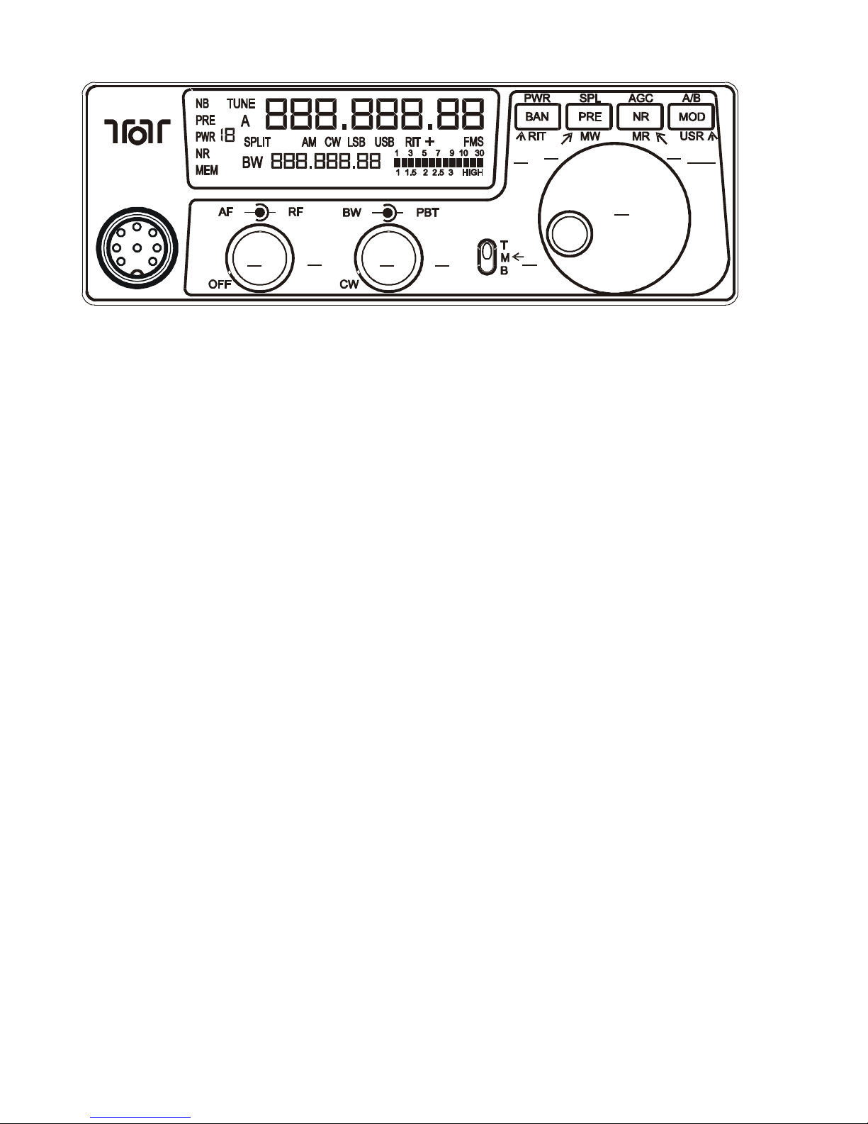
TEN-TEC ARGONAUT VI MODEL 539 QUICK START GUIDE
1
2
3 4
5
6
7
8
10
9
Argonaut VI
1. AF Gain / Power– Audio Level Adjustment
POT
2. RF Gain – Level Adjustment POT
3. BW – Bandwidth POT
4. PBT – Pass Band Tuning POT
5. Three Position Switch indicating Push
Button Definitions (Top,Middle,Bottom)
6. Main Tuning Knob
The following are valid only when the BW
Adjustment POT is not fully counter clockwise
7. PWR – (T) Transmit Power Level
8. SPL – (T) Split Operations
9. AGC – (T) Automatic Gain Control
10. A/B – (T) A Swap B, Held = A=>B
NOTE: USR buttons shown above are defaults
shipped from factory. Use the setup539 PC GUI
to tailor these.
Argonaut VI Model 539 Quick Start Guide Release 1.00 – December 11, 2012 2
Part #74480
Printed in USA
BAN – (M) Band Up/Down
RIT – (B) RIT On/Off/adjust
PRE – (M) Pre Amp (ON/OFF)
MW – (B) Memory Write
(F/M/S)
NR – (M) Noise Reduction (DSP 1..10)
NB – (M) Noise Blanker ON/OFF,
Held=Level
MR – (B) Memory Recall
MOD – (M) Mode Adjust
(AM/CW/LSB/USB)
USR – (B) CW Speed = 5 .. 50wpm
USR – (B) Voice Modes = MicGain, Held =
Switch MIC input vs LINE input
The following are valid only when the BW
Adjustment POT IS fully counter clockwise
IN VOICE MODES:
7. (BAN) - Monitor Level
8. (PRE) - Speech Processor
9. (NR) – AN On/Off (1 beeps=off,2=on)
10. (MOD) - Undefined
IN CW MODE:
7. (BAN) - QSK Delay – 0 = full breakin.
8. (PRE) - Sidetone Level
9. (NR) - Sidetone Frequency (Hz)
10. (MOD) - Dit Spacing/ Weighting. Press
again to adjust Curtis Mode A/B
(0=A, 1=B)
Press/Hold Functions on Power UP
Three Position Switch TMB in T position.
7. (PWR) - Configuration Menu
Release when you see “F1 xxx”
8. (SPL) - Master Reset
Release when you see “reset”
9. (AGC) - Undefined
10. (A/B) - Firmware Flash Update Mode
Release when you see ALC LED Flash
ON/OFF/ON 1 second cycle
 Loading...