

Page 1

MODEL 1215
ANTENNA TUNER KIT
ASSEMBLY & OPERATIONAL MANUAL
Release “B” 6/28/11
1 1215 Antenna Tuner Manual Part # 74449
Page 2

2 1215 Antenna Tuner Manual Part # 74449
Page 3

TABLE OF CONTENTS
NOTE: This manual is divided into two sections, the “Reference Section” which covers the
meter's specifications and general information and the “Assembly Section” which covers the
actual assembly and check-out of the kit. The “Assembly Section” is last since it will seldom
be referenced after the wattmeter is built and tested for the first time. The “Reference
Section” is essentially the owner's manual for the completed unit.
• REFERENCE SECTION
◦ Tuner Specifications
◦ General Introduction
◦ Circuit Overview
◦ Schematic Drawing
◦ Parts List / Bracket Drawings
◦ Operating Tips
◦ Troubleshooting Chart
◦ Optional Balun for Balanced Feeders
• ASSEMBLY SECTION
◦ Kit Assembly Suggestions
◦ Required Tools & Supplies
◦ Getting Started
◦ Phase I: Assembly of Rotary Inductor (L2)
◦ Phase 2: SWR Bridge Circuit Board Assembly
◦ Phase 3: Meter Switch & SWR Set Pot Assembly & Wiring
◦ Phase 4: Antenna Switch Wiring
◦ Phase 5: Chassis Assembly & Wiring
◦ Phase 6: Wattmeter Calibration and Checkout
3 1215 Antenna Tuner Manual Part # 74449
Page 4

MODEL 1215 TUNER SPECIFICATIONS
CIRCUIT TYPE: High Pass “T” Network
RF POWER RATING: 200 Watts maximum
FREQUENCY RANGE: 1.8 – 30 MHz
WATTMETER RANGES: 20 Watts, 200 Watts
OUTPUT MATCHING RANGE: SWR up to 10:1
INPUT IMPEDANCE: 50Ω Resistive when tuner properly matched
CAPACITOR RATING: 10 - 210 pf @ 1000 Volts
INDUCTOR: Toroidal rotary, 0.2 – 18 uH
DC POWER SOURCE: 12 – 16 Volts @ 150 ma (for meter illumination)
ENCLOSURE SIZE: 9.5”W x 4.2”H x 5.5”D
(with knobs & connectors, the overall depth
is approximately 7.25”)
WEIGHT: 3.5 lb (1.8 kg)
4 1215 Antenna Tuner Manual Part # 74449
Page 5

GENERAL INTRODUCTION
The Model 1215 is a full featured antenna tuner designed for the ham operator using
transmitters or transceivers from QRP through 200 watts. A wide matching range combined
with an integral wattmeter and SWR bridge provides all the necessary capabilities to ensure
efficient operation with minimal RF losses due to impedance mismatches between the
feedline and radio. Up to four antennas can be selected via a front panel switch. One of
those antennas can be a single wire antenna and provision has been made to add an internal
balun for connecting to balanced feedlines.
Our goal is to provide the builder with the satisfaction of “doing it yourself” and, in the process,
furthering his or her understanding of the circuit operation. Understanding the circuit
operation removes much of the “mystery” often encountered in adjusting an antenna tuner.
Follow the assembly instructions carefully and you will be rewarded with an antenna tuner
with professional performance and appearance. Should you have any questions, Ten Tec
Customer Service is available to help.
5 1215 Antenna Tuner Manual Part # 74449
Page 6
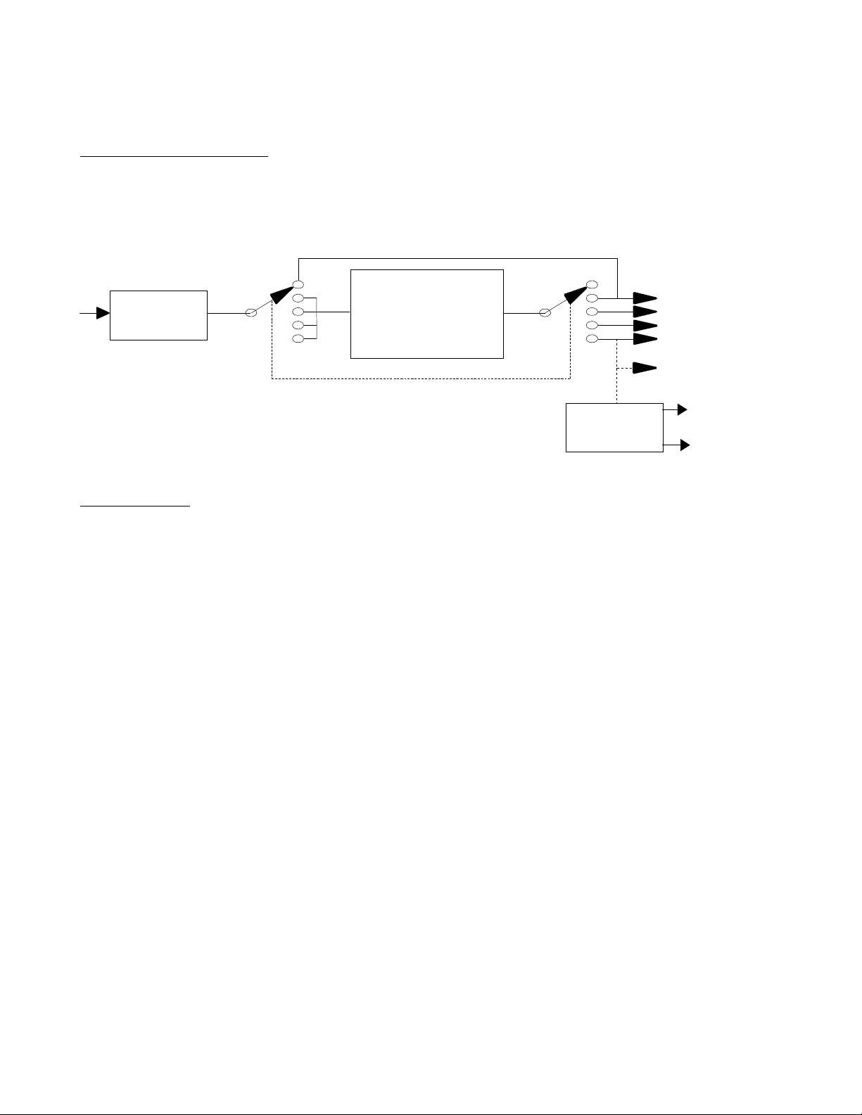
1215 BLOCK DIAGRAM
CIRCUIT OVERVIEW
BYPASS
SWR
BRIDGE
“T” MATCHING
NETWORK
OPTIONAL
BALUN
ANT #1
ANT #2
ANT #3
ANT #4
SINGLE WIRE
BALANCE
D
LINE
SWR BRIDGE
The internal SWR bridge is physically connected between the tuner input and the radio. The
bridge performs three functions:
1. Measures transmitter output (forward) power
2. Measures the reflected power at the tuner input (“Radio”) port
3. Displays the SWR on the built-in meter
The SWR measurement setting is used when adjusting the tuner for optimum performance.
In this mode, the tuner is adjusted to produce, ideally, a 1:1 SWR as seen by the radio.
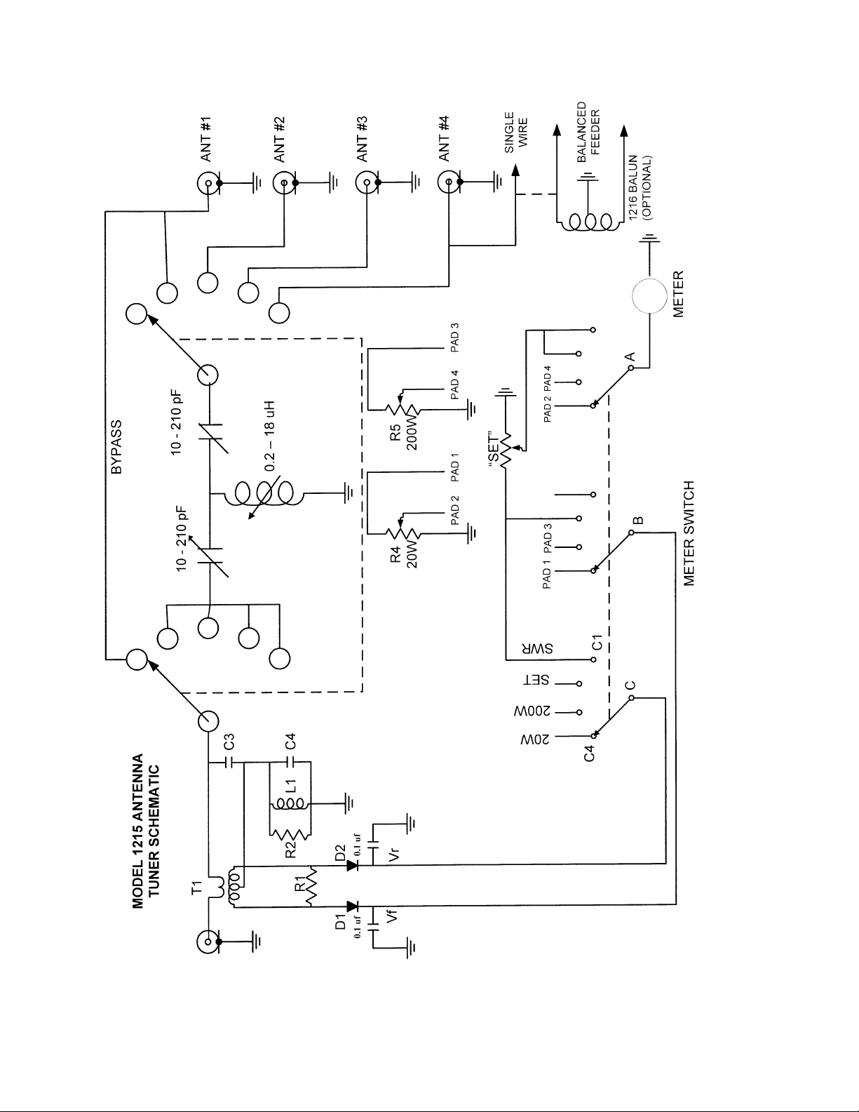
The bridge consists of an RF transformer, wound on a toroidal core, with the main
transmission line passing through it. This allows sampling both the forward and reflected
power levels present at that point. The outputs from the transformer are detected by two
Schottky diodes, D1 and D2, and the DC voltage produced is used to drive the meter to
display either the forward or reflected power. When the tuner properly matches the antenna
system to 50Ω, the reflected power reading will be zero.
In the forward power measurement mode, a potentiometer is connected in series with the
meter to display either 20 watts or 200 watts full scale. Once calibrated, the pots should need
no further adjustments.
Since SWR is a measurement of the ratio of forward to reflected power, an “SWR Set” control
is included on the front panel of the tuner. With the transmitter operating at it's desired power
level, the meter is placed in the SWR Set mode and the Set pot is adjusted for a full scale
6 1215 Antenna Tuner Manual Part # 74449
Page 7

reading. The switch can then be changed to the “SWR” setting and the value of SWR read
directly. If the output power level is changed, the “Set” pot will need to be readjusted to
maintain an accurate SWR reading.
ANTENNA SELECTION
The antenna tuner is equipped with a five position antenna selector switch. In the first
position, BYPASS, the output of the SWR bridge is connected directly to Antenna Connector
#1. This keeps the power and SWR measurement circuitry active, but bypasses the tuner
circuitry. Note that the bypass position only functions for antenna #1.
In positions 2 through 5, the tuner is connected to antenna ports #1 to #4 in sequence. To
connect a single wire antenna to the tuner, use the insulated terminal indicated on the rear
panel. The antenna switch must be set to Antenna #4 for the single wire feed. To connect the
tuner to an antenna with a balanced feed i.e., ladder line, a balun (balanced to unbalanced
transformer) is required. The 1215 does not come equipped with a balun, however there are
feed through posts on the rear panel which will allow a balun to be mounted internally and it's
connections brought out through the rear panel. A jumper (supplied) between the “Single
Wire” and “Balanced Feeder” post needs to be installed when a balun is being used. As with
the single wire feed, the tuner must be set for Antenna #4 when using the balun. The
“Balanced Feeder” jumper should be removed if Antenna #4 is being used for a coaxial or
single wire antenna feed. Ten Tec offers an internal balun as an accessory for the 1215 tuner.
The model number for that balun is 1216. As an alternative, information on building a balun
can be found in the “Optional Balun” section of this manual or any recent edition of the ARRL
Antenna Book. A web search with the keyword “4:1 balun” will provide many references for
building a balun for tuner applications.
ANTENNA TUNER CIRCUITRY
The antenna tuner is a high pass “T” network with two series variable capacitors and a shunt
variable inductor connected between them and ground. This configuration allows a wide
range of impedances to be matched to the 50Ω output impedance of the radio. This
configuration is fairly easy to tune if the proper procedure is followed. The tuning procedure is
outlined in the “Operating Tips” section of the manual.
7 1215 Antenna Tuner Manual Part # 74449
Page 8
8 1215 Antenna Tuner Manual Part # 74449
Page 9

1215 ANTENNA TUNER PARTS LIST
PART # DESCRIPTION QTY
CHASSIS ASSEMBLY
23227 Cap, Air Variable 2
27007 Lamp Socket, Bayonet 1
30894 10k Panel Mount Pot 1
32077 Rotary Switch ; 3 Pole / 4 Position 1
32098 Rotary Switch ; 2 Pole / 5 Position 1
34011 Pilot Lamp ; Bayonet Base 1
34043 Panel Meter 1
34070 Knob - “Meter Switch” & “SWR Set” 2
34071 Knob - “Antenna Switch” & “Inductance” 2
34072 Knob - “Transmit Match” & “Load Match” 2
35007 SO239 Coax Receptacle 4
35132 DC Power Jack ; 2.1mm 1
35402 DC Power Plug ; 2.1mm x 5.5mm 1
42010 Panel Bushing - “Ant Switch” & “Inductance” 2
46010 Wire, Hookup, #24 Black Stranded 24”
46011 Wire, Hookup, #24 Brown Stranded 15”
46012
46013 Wire, Hookup, #24 Orange Stranded 12”
46015 Wire, Hookup, #24 Green Stranded 15”
46016 Wire, Hookup, #24 Blue Stranded 12”
46018 Wire, Hookup, #24 Grey Stranded 24”
46019
46057
46059
90681 Nylon Feed-Thru Insulator 6
91217-6 Phenolic Shaft 1
91482 Shaft Coupler – 1/4” 1
93946 Flat Jumper for Rear Panel 1
Wire, Hookup, #24 Red Stranded 15”
Wire, Hookup, #24 White Stranded 24”
Wire, Hookup, #24 White / Yellow Stranded 12”
Wire, Hookup, #24 White / Blue Stranded 6”
80925 INDUCTOR SUB-ASSEMBLY
38060 C Ring 1
77001 Copper Braid ; 3/16” Wide 4.8”
80924 Inductor Mount Bracket Assembly 1
21045 Toroid Core – Ferrite (large) 1
46076 #18 Solid, Silver Plated Wire 15 ft
90682 Toroid Bottom Cover 1
90683 Toroid Top Cover 1
90677 Rotor 1
90679 Hub 1
90690 Contact Stiffener 1
90691-1 Modified Contact 2
91369 Aluminum Inductor Shaft ; 1/4” Dia 1
9 1215 Antenna Tuner Manual Part # 74449
Page 10

PARTS LIST (CONTINUED)
PART # DESCRIPTION QTY
82062 SWR BRIDGE SUB-ASSEMBLY
21003 Toroid Core – Ferrite (small) 1
21007 1mH Inductor 1
23261 Ceramic Capacitor – 0.1uF 2
23371 Ceramic Capacitor – 10pf / 1kv 1
23400 Ceramic Capacitor – 470 pf / 100V 1
28071 Schottky Diode – BAT41 2
30082 1
30136 1
30806 1K Variable Resistor (Pot) 2
35007
46022 Wire, Solid #28 Red 18”
46070 Wire, Solid #28 Green 18”
82080 PC Board Assembly 1
41011 #10 Solder Lug 4
41039 #4 Solder Lug ; internal tooth 3
42003 Rubber Mount Foot 4
51002 #4 Lockwasher 15
51007 #10 Flat Washer ; 7/16” OD 11
51011 Fiber Shoulder Washer ; 5/8” 4
51034 #10 Lockwasher 4
51039 3/8” Flat Washer 4
54002 4-40 Hex Nut 15
54003 3/8”x32 Hex Nut 4
54005 10-32 Hex Nut 4
54016 Self-Threading Nut 1
54017 10-32 Wing Nut 4
54029 2-56 Hex Nut 4
54048 Metric M9 x 0.75mm Nut 1
60001 4-40 x ¼” Screw 2
60003 4-40 x 3/8” Screw 7
60035 10-32 x 3/4” Screw 1
60036 10-32 x 1-1/4” Screw 3
60067 2-56 x 1/4” Screw 4
60069 4-40 x 3/8” Screw w/captive lockwasher 10
60080 4-40 x 3-16” Flat Head Screw 8
60092 Screw, 6-32 x 3/16”, Black 2
65009 #4 x 1/4” Pan Head Screw 2
93954-CN2A Chassis 1
93955 Cover 1
93956 Meter Support Bracket 1
93957 Antenna Switch Bracket 1
68Ω 2W Resistor (blue-gray-black)
680Ω 1/4W Resistor (blue-gray-brown)
SO239 Coax Receptacle
MECHANICAL PARTS
1
10 1215 Antenna Tuner Manual Part # 74449
Page 11
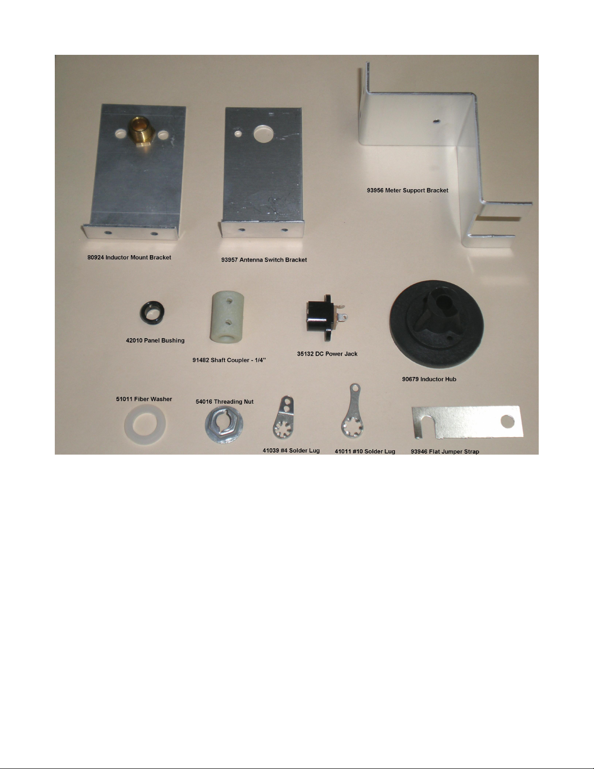
MECHANICAL PARTS IDENTIFICATION
11 1215 Antenna Tuner Manual Part # 74449
Page 12

OPERATING TIPS
Operation of the tuner is fairly straight forward. The most difficult portion is usually the “first
tuning” for a given band or antenna. The following procedure will greatly simplify this first
tuning, as well as all subsequent tuning:
1. Set the “Transmitter” and “Load” capacitors and the “Inductance” to maximum.
2. Set the “Meter” switch to “SWR SET” and adjust the SWR pot fully counter-clockwise
3. Place the transmitter on frequency and reduce the power as far as possible
4. Key the transmitter and adjust the SWR pot for a full scale reading (increase the
transmitter power slightly if a full scale reading can not be obtained.
5. Set the “Meter” switch to “SWR” and adjust the inductor for a minimum reading
6. Adjust the “Transmitter” and “Load” capacitors for a minimum SWR reading
7. If the SWR can not be reduced to 1:1, adjust the inductor switch one position higher or
lower.
8. Adjust the “Transmitter” and “Load” capacitors for a minimum SWR reading
9. If the SWR is higher than the original value, adjust the inductor switch two positions in
the opposite direction and repeat the capacitor adjustments.
Using this procedure, the minimum SWR should be obtained relatively quickly. Note that
some loads may not be capable of being matched to a 1:1 SWR. In such cases, leave the
tuner set for the lowest SWR achievable. An SWR of 2:1 or less is generally acceptable to
most transmitters and does not result in any appreciable loss in strength of the radiated
signal.
Recording the inductor and capacitor settings for several frequencies across the desired
bands will allow a quick pre-setting of the tuner later on.
Although the tuner is rated to operate at a 200 watt level, it should not be tuned at this level,
other than for minor adjustments of the capacitors. Do not switch the inductor while keyed at
power levels greater than about 25 watts. Always pre-tune the tuner at the lowest possible
power level.
If the tuner is to be used with a single wire feed antenna, connect the feed wire to the “Single
Wire” terminal on the rear panel. The antenna selector switch must then be set to “Antenna
4”. Note that, if a single wire feed is being used, there must not be another antenna
connected to the “Antenna 4” SO-239 connector.
If a balanced feeder is to be used, connect the supplied jumper bar between the “Single Wire”
terminal and one of the “Balanced Line” terminals on the rear panel of the cabinet. The
balanced feeder is then connected to the two Balanced Feeder terminals. NOTE: Using a
balanced feeder requires that a balun be installed! The balun can be enclosed inside the
tuner cabinet and connected to the provided Balanced Line terminals. See the “Optional
Balun” section of this manual for further information. As with the single wire feed, there must
not be any other antenna connected to the “Antenna 4” SO-239 connector when using a
balanced line fed antenna.
12 1215 Antenna Tuner Manual Part # 74449
Page 13

A final point to remember whenever using an antenna tuner is that the “antenna” itself is not
Check SWR in “Bypass” mode ; Check SWR with a 50
Ώ load and tuner
to “Radio” port
Verify that power level is not in excess of 200 watts ; Check that inductor
inductor shaft does not contact TX and Load capacitors.
being tuned. The tuner simply transforms the impedance seen at the radio end of the feedline
to 50 Ohms. Any mismatch between the antenna itself and the feedline will remain
unaffected. That mismatch can only be corrected by installing a matching device directly at
the antenna feedpoint. In most cases, the mismatch between the antenna and feedline is not
the limiting issue. A detailed discussion of this can be found in the ARRL Antenna Book or
other ham publications.
TROUBLESHOOTING CHART
If any difficulties are encountered with the 1215 Tuner, check the following items first:
• Verify that the radio is connected to the “Radio” connector on the rear panel.
• Verify that the Antenna Switch is in the correct position for the antenna being used.
Once the above have been verified, use the following chart if problems still exist:
PROBLEM SYMPTOM CHECK THE FOLLOWING:
High SWR can not be
reduced
SWR Meter not functioning
properly
Power Meter not functioning
Tuning capacitors and / or
inductor have no effect
Incorrect Power Readings
Arcing inside cabinet
No meter backlight
Room is “hot” with RF
No antenna connected, or wrong antenna selected ; SWR “Set” control
set too high ; Tuner in “Bypass”
in “Bypass”; Verify setting of SWR “Set” control; Verify radio connected
Check operation with tuner in “Bypass” and a 50Ώ load connected to
“Ant 1” port. ; Verify that radio is connected to “Radio” port.
Verify that tuner is not in “Bypass” ; Confirm that an antenna is
connected and selected.
Check readings with a 50Ω load on “Ant 1” and put tuner in “Bypass” ; If
SWR function is working normally, check power calibration.
contact is not “between” two stops. Check that ground braid from
Verify that 12 – 16 VDC is applied to DC input connector. Positive to the
center pin and negative (ground) to the connector shell. Verify that bulb
is not burned out.
Verify that tuner ground lug is connected to station ground along with the
radio. Station ground should be common to all equipment and be tied to
an external ground rod. If a single wire, or balanced feeder, is used, try
re-routing them away from any of the equipment.
13 1215 Antenna Tuner Manual Part # 74449
Page 14

If your radio is equipped with an internal SWR / Power meter, it is not unusual for a small
difference to be noted between the SWR shown on the tuner meter and the SWR shown on
the radio's meter. There will be some minor variances due to the differences between the
SWR bridge in the radio and the bridge used in the tuner, however the major contributor is
generally the cable length between the radio and the tuner. That can be verified by
connecting a shorter or longer cable and noting if the difference in readings changes. In a
perfectly matched system, the interconnecting cable length becomes irrelevant. For less than
a perfect match, the measured SWR will vary depending on where along the cable the
measurement is made. In this case, the tuner's SWR meter and the radio's SWR meter are
located at different points on the cable and a reading difference is expected. Note that the
difference in readings will vary with frequency. The lower the frequency, the less difference is
generally seen. Since the radio's SWR meter is measuring the SWR at the radio, rather than
at the input to the tuner, adjust the tuner for minimum SWR as displayed on the radio's SWR
meter.
This assumes that there is no equipment connected between the radio and the tuner i.e., an
external low pass filter or other device. If there is something in between, temporarily connect
the radio directly to the tuner and re-check the readings. If they begin to correlate, the
intermediate device may have a problem or may simply be affecting the match between the
tuner and the radio. If the device is functioning normally, verify that the cables used are good
and, if so, use the SWR meter on the radio when adjusting the tuner.
14 1215 Antenna Tuner Manual Part # 74449
Page 15
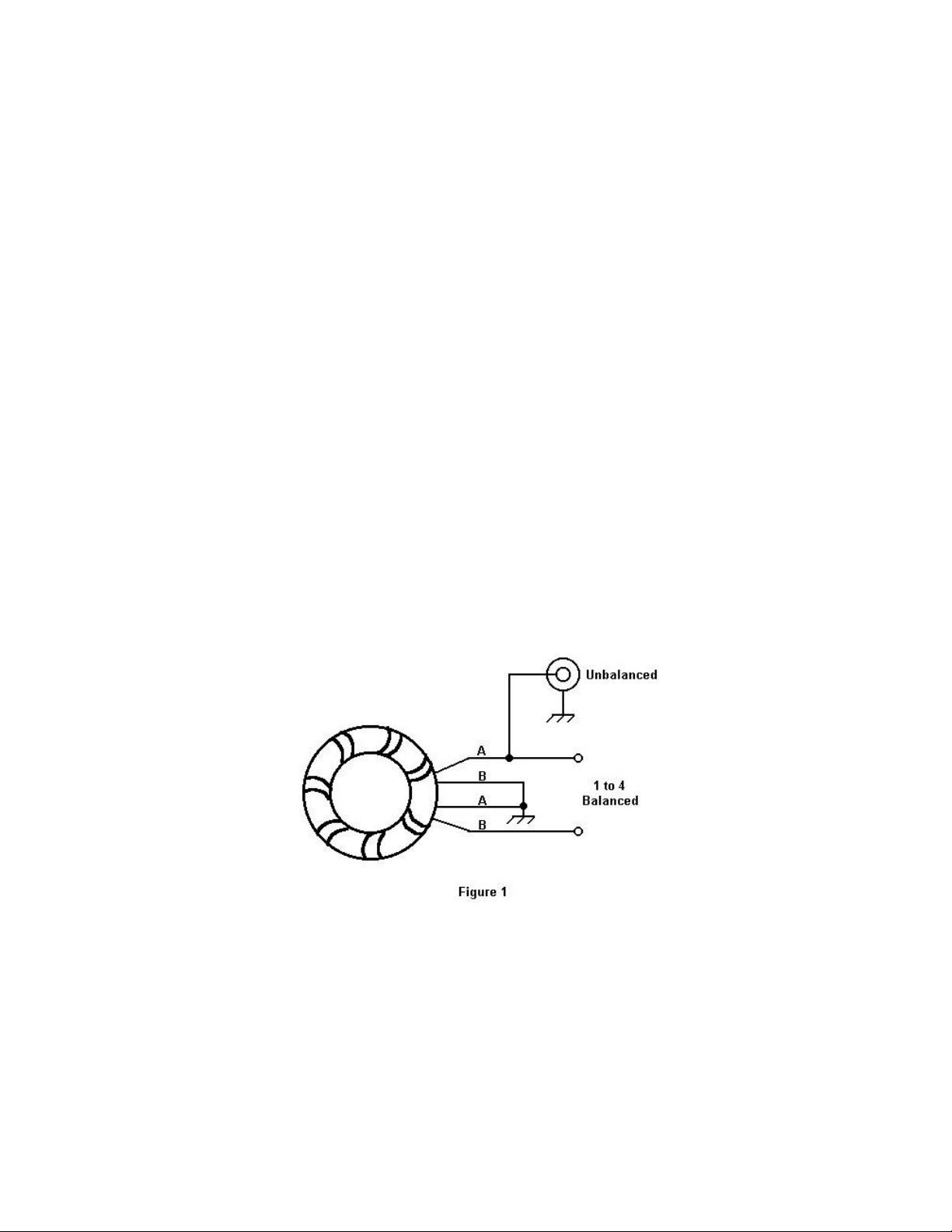
OPTIONAL BALUN FOR USE WITH OPEN WIRE (LADDER LINE) FEEDERS
The 1215 tuner is capable of connecting directly to open wire feeders if a 4:1 balun is
installed. The necessary insulated feed-thru terminals are provided on the rear of the cabinet
which allows for a balun to be installed inside the unit.
A 4:1 balun is a relatively simple device which can be built or purchased at fairly low cost.
Ten Tec offers one, Model # 1216, as an accessory for the 1215 tuner. For further
information, check the Ten Tec web page (www.tentec.com) or call our sales department at
(800) 833-7373. For more information about baluns, a web search using the key words “4:1
balun” will produce a long list of references.
The purpose of the balun is to convert the unbalanced output of the tuner to a balanced
output which will feed the open wire (ladder line) feeders used on several types of broadband
or multi-band antennas.
A balun can be built using a T200A-2 core with 13 bifilar turns of #16 Teflon coated wire,
connected as shown in Figure 1. Alternately, a T-200-2 core with 17 turns of #16 Teflon
coated wire can be used. Power handling capability is about 300 watts.
15 1215 Antenna Tuner Manual Part # 74449
Page 16

KIT ASSEMBLY
This section of the manual covers assembly of the Model 1215 Tuner. Assembly is done in a
number of “phases” designed to make assembly easier while allowing a number of “break”
points. The assembly phases are:
Phase I: Rotary Inductor Assembly
Phase II: SWR Bridge Circuit Board Assembly
Phase III: Meter Switch & SWR Set Pot Assembly & Wiring
Phase IV: Antenna Switch Wiring
Phase V: Chassis Assembly & Wiring
Phase VI: Wattmeter Calibration & Checkout
NOTE: This manual is available in pdf format at www.tentec.com. The pdf format allows you
to enlarge any of the drawings / photos in the event that there are any questions of what goes
where and how it is mounted and / or connected.
REQUIRED TOOLS / MATERIALS:
Tools / materials required for kit assembly include:
• Needle nose pliers
• Small pair of wire cutters
• Soldering iron (25 – 50W)
• 1/2” nut driver or socket
• Digital voltmeter (optional, for calibration)
• Philips head screwdriver
• Small flat (dial) screwdriver
• 60 / 40 (or 63 / 37) rosin core electronics solder
• Epoxy glue
Recommended tools include:
• Small bench vise
• Solder removal braid
• Sharp utility knife
• Ruler
• Work gloves (for pulling wire)
16 1215 Antenna Tuner Manual Part # 74449
Page 17

PHASE 1: ROTARY INDUCTOR ASSEMBLY
Kit Assembly Note: In this section, as in all the others, two check boxes are provided at
each step of the assembly. Check off each step as it is completed. Should you need to go
back to re-check your work, use the second check-off box as each previously completed step
is verified.
OVERVIEW
This sub assembly kit is packed separately for your convenience. Before working with the
Inductor parts kit, please read all of the assembly instructions first. Examine the various parts
and visualize how they fit together. Notice how the grooves in the toroid covers are designed
to assure uniform winding. We recommend building this coil assembly first because it is
necessary to secure the hub to the toroid with an epoxy glue after winding. Other phases of
the kit assembly can be completed while the coil assembly dries.
COIL WINDING PROCEDURE
The most important, and most difficult, part of winding the toroid is to make a good start. After
the first few turns, it will become progressively easier to wind.
While the grooves in the toroid covers provide uniform spacing, the winding must be kept tight
to prevent adjacent turns from shorting together. Treat each turn as having four components:
top, two sides and the inner side. Keep each side as tight as possible. Doing so will result in
smooth operation of the completed assembly. The “top” (outside) layer makes contact with
the rotor and consequently needs the turns to be as equally spaced and flat (tight) as
possible.
To prevent scarring of the silver plated wire, wrap protective tape around each jaw of any
pliers used in the winding process. Alternately, rubber tubing can be slipped over the pliers
jaws.
The wire will be routed through the center of the toroid many times during the winding
process. Avoid kinking the wire as it is passed through.
If a bench vise is used to hold the toroid assembly firmly, cushion the bare vise jaws with
wood shims or plastic strips to prevent damage to the nylon toroid shells.
The following directions presume winding the toroid from one end to the other. Some
builders may prefer to start in the middle and work toward each of the two ends. If you
elect to start in the center, be sure to follow the groove patterns exactly and start with
the middle of the silver plated wire at the midpoint of the toroid.
17 1215 Antenna Tuner Manual Part # 74449
Page 18
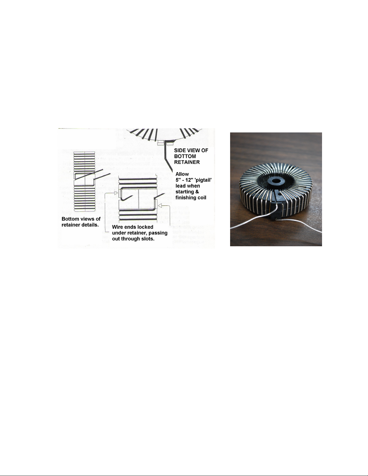
1. □□ Place the toroid core within the two nylon shells. While not necessary, it is OK
to use some glue sparingly to keep everything together (hot glue is ideal for this).
Epoxy glue is required only to secure the hub after winding.
2. □□ While most turns require pulling the full wire length through the center, you can
get started by looping 3 – 5 loose turns, leaving a “pigtail” lead of 6” to 12”.
3. □□ Lock the pigtail wire around the bottom retainer slot (see photo and drawing),
then use padded pliers to tighten the first several windings in place per the details
emphasized in the beginning of the coil winding procedure above.
4. □□ Loop the full length of wire back through the center and form the next turn
tightly. Be careful not to kink the wire.
5. □□ Repeat the preceding steps until all turns are made. It does get easier as the
wire gets shorter!
6. □□ After tightening the final turn, wrap the remaining wire through the other retainer
slot and cut the excess wire to leave another “pigtail” lead of 6” to 12”.
7. □□ Slip the hub into one side of the toroid and visualize the assembly before gluing:
the retainer slots are at the bottom, with the two hub holes aligned horizontally. See
photo on the top of the next page for reference.
18 1215 Antenna Tuner Manual Part # 74449
Page 19
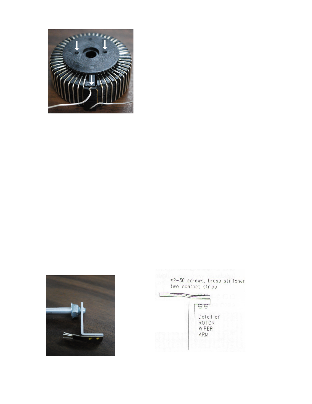
8. □□ Follow the glue manufacturer's directions and mix enough epoxy glue to
thoroughly coat the portion of the hub to be in contact with the toroid.
9. □□ Glue the hub to the toroid, aligning the hub per step 7. Set the glued assembly
aside with some weight on top or clamp the assembly together.
10.□□ Organize the following for assembly: rotor bracket, contact strips (2), contact
stiffener and two each #2-56 screws and nuts.
11. □□ Assemble the rotor in this order: #2-56 screws, stiffener strip, two contact strips,
bracket and #2-56 hex nuts. (See photo and drawing below – note that the photo
unit has rivets in place of the screws and nuts you will be using)
1. Align the holes of the rotor bracket with the contact strip holes
2. Align the stiffener on the contact strips
3. Insert screws through the stiffener, contact strips and rotor bracket (in that
order)
4. Attach the nuts
5. Tighten securely
6. With a pair of needle nose pliers, grasp the stiffener & contact strips just past
the edge of the rotor bracket and bend them slightly as shown below. This will
increase the contact pressure of the contacts to the inductor wire.
19 1215 Antenna Tuner Manual Part # 74449
Page 20
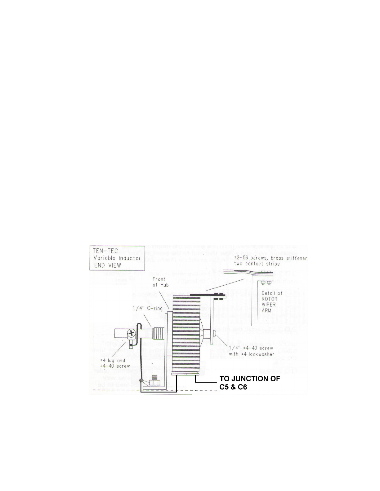
12.□□ Using a 7/16” nut driver, thread the 1/4” thread cutting fastener on the rear of the
shaft, the end with internal threads for mounting mounting the wiper arm. Thread it
onto the shaft about 3/8” and then back it out until there is just enough room to slip the
rotor onto the end of the shaft (see above). It will be necessary to use a small vise or
Vise-Grips to hold the rod while the fastener is being threaded on.
13.□□ Mount the rotor to the 1/4” shaft with one #4-40 1/4” screw and one #4 lock
washer. Tighten securely.
14.□□ No further work should be done with this inductor assembly until the epoxy is set
per the manufacturers directions. Proceed now to Phase II of this project (SWR Bridge
Circuit Board Assembly). Return when the epoxy bond from the hub to toroid has set.
AFTER THE EPOXY IS SET:
1. □□ Mount the hub / toroid to the aluminum bracket (with the pressed in brass
bushing) using the two #4, 1/4” self tapping screws through the bracket and into the
hub. Do not fully tighten the screws at this time. The bracket faces away from the
toroid, toward the front panel of the tuner. (See drawing)
2. □□ From the rear of the toroid / hub, slide the front end of the rotor shaft / wiper
assembly through the hub until stopped by the thread cutting fastener.
20 1215 Antenna Tuner Manual Part # 74449
Page 21

3. □□ Slide the “C” ring over the front end of the rotor shaft and slide it downward until
it snaps into the groove just in front of the brass bushing. Tighten the thread cutting
fastener as needed to minimize slippage of the shaft in the hub without making the
shaft difficult to turn. Note that it may be easier to adjust the thread cutting fastener by
temporarily removing the wiper assembly and using a nut driver. Correct positioning of
the fastener is where it almost touches the wiper bracket. (Refer to photo on Page 18)
Now tighten the two screws fastening the hub to the bracket.
4. □□ Install the #4 solder lug and #4-40 x 3/8” screw in the threaded hole near the
front of the shaft. (Refer to the drawing on the previous page)
5. □□ Solder one end of the braid to the solder lug mounted on the shaft.
6. □□ Adjust, if necessary, the rear, thread cutting, tension fastener and the front “C”
ring to assure good contact to the windings by the contact arm with minimum sliding of
the shaft in the hub.
7. □□ Set the assembly aside.
21 1215 Antenna Tuner Manual Part # 74449
Page 22

PHASE II: SWR BRIDGE CIRCUIT BOARD ASSEMBLY
OVERVIEW
The SWR Bridge Circuit Board Assembly consists of the bare circuit board, Part # 78366, the
input antenna connector, a toroidal RF transformer and assorted passive components. The
“component side” of the board is the side with the silk screened outlines of each of the
components along with their component designators. All parts, with the exception of the input
connector and associated standoffs, will mount on the component side of the board.
When mounting the electronic components (resistors, inductors, diodes and capacitors),
insert their leads through the indicated solder pads and pull them snugly down to the board.
On the solder side, bend the leads slightly where they emerge from the board to hold the
components in place for soldering. The leads will be cut off after soldering. The two
potentiometers will “snap” into position when inserted into the board. The resistors,
capacitors and inductors can be installed in either direction. The diodes must be installed
with their banded end corresponding to the banded end screened onto the board. For these
passive components, the component value, followed by it's marking, is shown within the
parentheses. Instructions for winding and installing the small toroid RF transformer will
discuss proper orientation of the device when mounting it on the circuit board.
22 1215 Antenna Tuner Manual Part # 74449
Page 23

CIRCUIT BOARD ASSEMBLY
Refer to Figure 2 in the Appendix for the following steps:
1. □□ Install resistors R1 (68Ω, 2 Watt, Blue-Gray-Black) and R2 (680Ω, 1/4Watt,
Blue-Gray-Brown) onto the circuit board.
2. □□ Solder each of the resistor leads and clip off the excess.
3. □□ Install inductor L1 (1 mH, Brown-Black-Red), capacitors C1 (0.1 uf, “104”), C2
(0.1 uf, “104”), C3 (10 pf, “10k”) and C4 (470 pf, “471”) onto the circuit board.
4. □□ Solder each of the leads and clip off the excess.
5. □□ Paying attention to the banded ends, install diodes D1 (“BAT 41”) and D2 (“BAT
41”) onto the circuit board with the banded ends as shown on the board.
6. □□ Solder each of the leads and clip off the excess.
7. □□ Insert the two potentiometers, R4 (1kΩ) & R5 (1kΩ), into the circuit board. Their
terminals will “snap” into place when properly seated.
8. □□ Solder each of the three terminals on each potentiometer to the board. There is
no need to clip any of these leads after soldering.
9. □□ Mount the SO-239 RF connector onto the two standoffs on the solder side of the
circuit board using two 4-40x3/8” screws with attached captive split washers. The
center pin of the connector should protrude slightly though the solder pad on the board.
10.□□ Solder the center pin to the circuit board. Ensure that the pad is completely
filled with solder with no visible gaps.
11. □□ Perform an inspection on the board to ensure that all components are in their
correct location and that all leads are soldered and clipped as necessary. Temporarily
set the circuit board assembly aside.
23 1215 Antenna Tuner Manual Part # 74449
Page 24

RF TRANSFORMER ASSEMBLY
The RF transformer is used to sample the forward and reflected power levels so that they can
be displayed on the front panel meter. The main winding is known as “bifilar” and consists of
two twisted parallel wires wound on the core, as compared to “conventional” transformers
which have “single wire” secondary windings. The primary side of this transformer will consist
of a single loop of wire passing through the center of the coil.
The first step is to prepare the main winding.
1. □□ Take the piece of Red colored #28 varnished wire ( Part #46022) and the piece
of Green colored #28 varnished wire (Part # 46070) and hold them parallel to each
other.
2. □□ Twist one end of each together and clamp them with a small vise or anything
which will hold them in position.
3. □□ Pull the two wires horizontally toward you (hold them 4” - 6” apart) and begin
twisting them together by turning the free ends together. Twist them until you see
about 3 – 4 twists per inch.
4. □□ Remove from the vise and separate the two ends which were originally twisted
together.
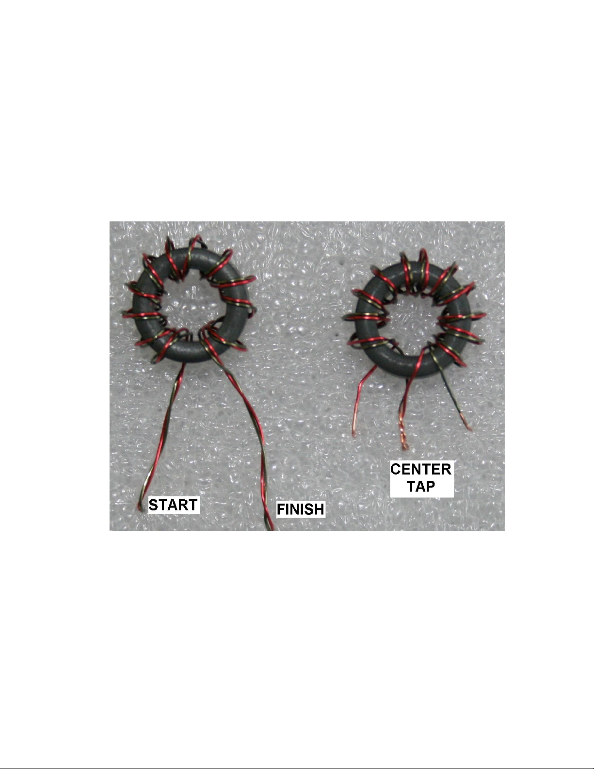
5. □□ Using the bifilar wire you have just twisted, wind 12 turns on the core, as follows.
The start, bottom, and clockwise directions for these windings are key to getting the
phasing correct in this directional coupler. START by leading the twisted wire through
the center of the core from the bottom. Pull the wire through until about 1-1/2 inches of
the two START wires remains outside the core. See Figure 3 (next page) for
reference.
6. □□ Continue winding around the core in a clockwise direction. Count each time the
wire pair goes through the center hole as a turn. Space the turns to take up most of the
core, as Figure 3 shows. The FINISH end will emerge from the center hole.
7. □□ Form a center-tap for the transformer by twisting together “Red Finish” to
“Green Start”. Be sure to scrape of the colored varnish first! When scraped, the wire
will have a shiny copper appearance. Refer again to Figure 3. Before proceeding,
check out this wiring with your ohmmeter or continuity checker as follows. “Red Start”
must have continuity to “Green Finish” AND ALSO to the center-tap. After assuring
that your connection is correct, solder the center-tap wires together.
8. □□ Mount the toroid on the circuit board, over the standoff post, and solder the
three leads to the pads as shown in Figure 2 (In Appendix).
24 1215 Antenna Tuner Manual Part # 74449
Page 25
9. □□ As shown in Figure 2, solder a piece of white wire to the plated through hole
coming from the SO-239 connector (RF Input) and route it down through the standoff in
the center of the toroid.
10.□□ Route the wire on the solder side of the board up through the plated through
hole next to the “RF Out” pad and solder it to the board (the pad is shown by a white
arrow in Figure 2). Clip off any excess at both ends of the wire.
11. □□ Check over all connections on the circuit board to make sure that all are
soldered and excess lead lengths have been clipped off. Set the board aside for now.
FIGURE 3
Proper winding of Toroid T1
25 1215 Antenna Tuner Manual Part # 74449
Page 26
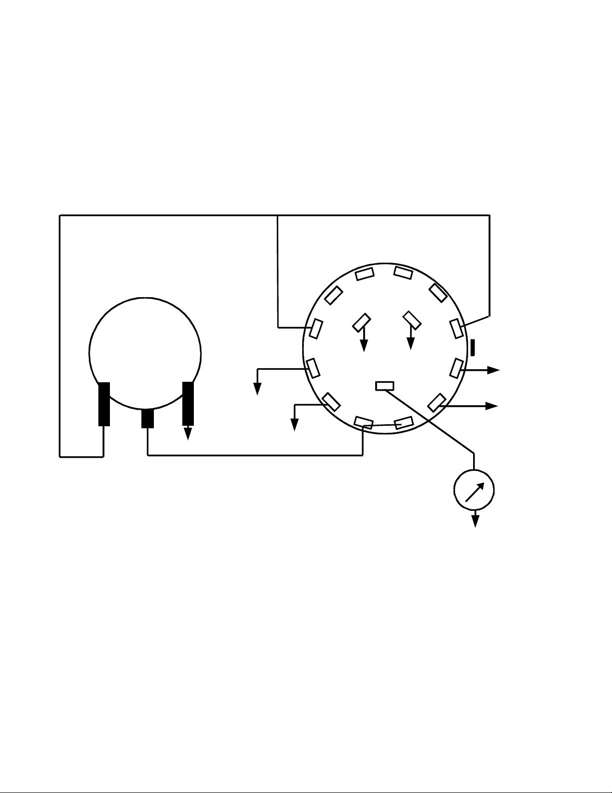
PHASE III: METER SWITCH & SWR SET POT ASSEMBLY WIRING
OVERVIEW
In this section, the meter switch and SWR Set pot will be pre-wired. It is much easier to wire
these prior to installing them into the chassis. The meter switch can most easily be identified
by looking at the contacts on the rear. There will be 12 solder contacts around the the edge
with three solder contacts, arranged in a triangle, in the center area. The pin designators are
shown below, along with a wiring diagram:
WHITE / BLUE WHITE / BLUE
“METER SWITCH”
(Rear View)
C4 C3
B1
C2
C
“Vr”
A
A2
C1
ORANGE
A4
A3
Switch Locating Tab
BROWN
GREEN
RED
+
“PAD 2”
“PAD 4”
“SET” POT
(Rear View)
GND
BLACK
WHITE
“PAD 3”
BLUE
GREY
“PAD 1”
B2
WHT / YEL
B3
B4
B
“Vf”
A1
WIPER
(CENTER TERMINAL)
GND
METER
BLACK
The assembly process consists of pre-cutting hookup wire to interconnect the switch and
“Set” pot as well as creating a small cable harness to connect to the SWR Bridge which will
mount to the rear panel of the tuner.
26 1215 Antenna Tuner Manual Part # 74449
Page 27

In preparation for wiring the switch and “Set” pot, prepare the following wires by cutting them
to the indicated length and then stripping 1/4” of insulation off each end except where noted
differently:
1. □□ 3-1/4” Red wire
2. □□ 3” Blue wire (strip 1/2” of insulation off one end and 1/4” off the other end)
3. □□ 9-1/4” Green wire
4. □□ 9-1/4” Brown wire
5. □□ 9-1/2” White / Yellow wire (white wire with a yellow tracer)
6. □□ 3” White / Blue wire
7. □□ 1-1/4” White / Blue wire
8. □□10-1/4” White wire
9. □□ 8-3/4” Grey wire
10.□□ 8-1/4” Orange wire
11. □□ 5” Black wire
Orient the switch and “set” pot in front of you as shown in the previous drawing. The pre-cut
wires will now be connected and soldered. Each connection, if it is to be soldered, will be
marked (Sx) where “x” is the number of wires at the joint being soldered. If there is only a
single wire, the indication will be (S1). If a wire passes through a joint, it will be considered as
two wires and marked (S2). (NS) means do not solder at this time.
Connect the pre-cut wires as follows:
1. □□ 3-1/4” Red wire to Terminal “A” of the switch (S1)
2. □□ 3” Blue wire to A1 (S2) & A2 (S1) of the switch and the center terminal of the
“Set” pot (S1)
3. □□ 9-1/4” Green wire to Terminal “A3” of the switch (S1)
4. □□ 9-1/4” Brown wire to Terminal “A4” of the switch (S1)
5. □□ 9-1/2” White / Yellow wire (white wire with a yellow tracer) to Terminal “B” on the
switch (S1)
27 1215 Antenna Tuner Manual Part # 74449
Page 28
6. □□ 3” White / Blue wire from Terminal “B2” of the switch (NS) to the left hand
terminal of the “Set” pot (viewed from the rear) (S1)
7. □□ 1-1/4” White / Blue wire to Terminal “B2” of the switch (S2) and Terminal “C1” of
the switch (S1)
8. □□10-1/4” White wire to Terminal “B3” of the switch (S1)
9. □□ 8-3/4” Grey wire to Terminal “B4” of the switch (S1)
10.□□ 8-1/4” Orange wire to Terminal “C” of the switch (S1)
11. □□ 5” Black wire to the right hand “GND” terminal of the “Set” pot (S1)
Set the switch and pot assembly to the side for the moment while the antenna switch
assembly is prepared.
PHASE IV: ANTENNA SWITCH WIRING
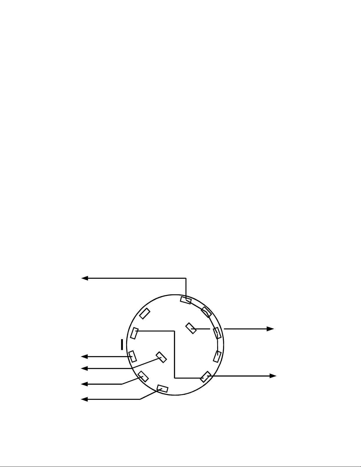
The antenna switch assembly is most easily installed if the antenna switch is pre-wired. This
is accomplished after mounting the switch onto it's associated bracket, Part # 93957.
Install the switch, with it's mounting tab through the hole in the bracket, with an M9 x 0.75
metric nut and flat washer as shown in Figure 1. (The nut and flat washer may come
assembled on the switch)
As with the meter switch, hook-up wire will be pre-cut and soldered to the switch before final
chassis assembly. The switch wiring diagram is shown below:
C5 ROTOR
ANTENNA SWITCH
(Rear View)
ANT #2
C6 ROTOR
ANT #3
ORANGE
RED
BLUE
GREY
B2
B3
B1
B4
B
B5
A5
A
BROWN
A4
A1
A3
A2
WHITE
BROWN
SWR BRIDGE
“RF OUT”
ANT #1
ANT #4
GREEN
28 1215 Antenna Tuner Manual Part # 74449
Page 29

Prepare the following wires by cutting them to the indicated length and then stripping 1/4” of
insulation off each end, except where noted differently:
1. □□ 4-1/2” White wire
2. □□ 1-1/4” Brown wire
3. □□ 2” Brown wire
4. □□ 8” Grey wire (strip 1” of insulation off one end and 1/4” off the other)
5. □□ 4-3/4” Blue wire
6. □□ 2-1/2” Red wire
7. □□ 2-1/2” Orange wire
8. □□ 3-1/4” Green wire
Refer to the drawing on the previous page to connect the wires to the Antenna Switch.
1. □□ 4-1/2” White wire to Terminal “A” of the switch (S1)
2. □□ 1-1/4” Brown wire to Terminal “B2” of the switch (S1) and Terminal “A1” (NS)
3. □□ 2” Brown wire to Terminal “A1” of the switch (S2)
4. □□ 8” Grey wire – route the 1” stripped end through Terminal “A5” (S2) to Terminal
“A4” (S2) to Terminal “A3” (S2) to Terminal “A2” (S1)
5. □□ 4-3/4” Blue wire to Terminal “B” of the switch (S1)
6. □□ 2-1/2” Red wire to Terminal “B3” of the switch (S1)
7. □□ 2-1/2” Orange wire to Terminal “B4” of the switch (S1)
8. □□ 3-1/4” Green wire to Terminal “B5” of the switch (S1)
29 1215 Antenna Tuner Manual Part # 74449
Page 30

PHASE V: CHASSIS ASSEMBLY & WIRING
In this section, all of the components will be mounted onto the chassis and interconnections
made.
METER SWITCH AND SWR “SET” POT INSTALLATION
1. □□ Remove the nut and flatwasher from the meter switch.
2. □□ Re-install the nut on the switch and thread it approximately halfway down the
bushing.
3. □□ Install the switch into the lower left hand hole on the front panel with the “A”
terminal toward the bottom of the chassis. Install the flatwasher onto the bushing and
an M9 x 0.75 metric nut over that. If the bushing protrudes through the nut or if there is
not enough bushing showing to thread the nut onto, remove the switch and adjust the
“inside” nut in or out to set the amount of bushing protruding through the front panel.
When the outside nut is installed, it should be essentially flush with the end of the
bushing. A little variation, either way, is acceptable. NOTE: a 3/8” nut will fit on the
switch, but will appear to be a bit loose. The metric nut is slightly smaller. Make sure
that the correct nut is used or the switch will loosen up later!
4. □□ Tighten the external nut securely with a crescent wrench or nut driver, taking
care not to scratch the front panel paint.
5. □□ Remove the nut and flat washer from the “SET” pot and install the pot into the
front panel with the locating tab in the small hole below the main control hole. Place
the flat washer and nut over the bushing protruding through the front panel and tighten.
Take care not to scratch the paint on the front panel.
6. □□ Locate the meter bracket (part # 93956), lamp socket and a #4 solder lug.
7. □□ Using a 1/4” 4-40 screw, nut and lockwasher, fasten the lamp socket to the
bracket as shown in Figure 1 in the Appendix. The solder lug should be placed
between the meter bracket and lamp socket and oriented to face toward the middle of
the chassis. Place the lockwasher inside the meter bracket, under the nut. Tighten
securely.
8. □□ Place the meter in the front panel hole and then attach the meter bracket to the
bottom of the chassis using two 3/8” 4-40 screws, lockwashers and nuts. Insert the
screws up through the bottom of the chassis.
30 1215 Antenna Tuner Manual Part # 74449
Page 31

9. □□ Solder the red lead from the meter switch to the “+” terminal of the meter. (S1)
The “+” terminal is the one toward the center of the chassis.
10.□□ Attach the black ground lead from the “SET” pot to the solder lug on the rear of
the meter bracket. (NS)
11. □□ Cut a 3-3/4” piece of black wire and strip 1/4” of insulation off each end.
12.□□ Solder one end of the black wire to the meter “-” terminal and connect the other
end to the solder lug on the rear of the meter bracket. (NS)
13.□□ Locate the previously assembled SWR Bridge board.
14.□□ Remove the two 4-40 screws from the SO-239 connector and then insert the
connector from the inside of the chassis through the rear panel hole labeled “RADIO”.
15.□□ Secure the connector to the rear panel using the two screws previously
removed. Tighten securely.
16.□□ Locate the 2.1mm DC power connector.
17.□□ Prepare a 6-3/4” Red and a 5-1/2” Black wire. Strip 1/4” of insulation from each
end.
18.□□ Solder one end of the Red wire to the “+” terminal of the DC connector (S1).
See drawing.
19.□□ Solder one end of the Black wire to the “-” terminal of the DC connector (S1).
See drawing.
+ Terminal
- Terminal
20.□□ Install the connector from the inside of the rear panel and attach it using two 1/4”
2-56 screws and nuts.
21.□□ Connect the black wire from the DC connector to the solder lug on the meter
mounting bracket, by the pilot lamp mounting screw. (NS)
31 1215 Antenna Tuner Manual Part # 74449
Page 32

22.□□ Solder the red wire from the DC connector to the solder lug at the base of the
lamp socket. (S1)
23.□□ Locate the four remaining SO-239 antenna connectors.
24.□□ Install the connectors at “Ant 1”, “Ant 2”, “Ant 3” and “Ant 4”. Use two 4-40 x
3/8” screws with attached split washers and two nuts at each location. Tighten
securely.
25.□□ Using a #10 x 3/4” screw, attach a #10 solder lug to the inside of the chassis at
the hole marked “GROUND”. Use a #10 lockwasher and nut on the outside of the
chassis.
26.□□ Install two #10 flat washers and a wing nut on the threaded end of the GROUND
screw.
27.□□ Locate six of the #90861 Feed Thru Insulators, three #10 solder lugs, three #10
x 1-1/4” screws, three #10 nuts, six #10 flat washers and three Wing Nuts.
28.□□ At each of the single or balanced wire feed points, install an insulator on each
side of the rear chassis. Slip a #10 solder lug over a #10 x 1-1/4” screw and insert it
into the feedthru from inside the chassis.
29.□□ Outside the chassis, slip a #10 flat washer and a #10 lockwasher onto each of
the three screws. Follow that with a #10 nut. Tighten securely.
30.□□ Install two #10 flat washers and a wing nut on the threaded ends of the #10
screws protruding through the feedthru insulators on the rear of the chassis.
31.□□ Locate the two black plastic 1/4” snap in bushings. From the front of the front
panel, insert one into the “Antenna” selector hole and the other in the “Inductance”
hole.
32.□□ Install the antenna switch behind the “Ant 1” connector. Screw it to the chassis
floor using two 4-40 x 3/8” screws, lockwashers and nuts. Feed the screws in from
underneath the chassis.
33.□□ Attach the insulated 1/4” coupler to the shaft of the antenna switch using one of
the black 6-32 x 3/16” screws.
32 1215 Antenna Tuner Manual Part # 74449
Page 33

34.□□ Insert the 1/4” diameter, 3-1/4” long insulated shaft through the front panel and
into the coupler on the antenna switch and tighten it down using a black 6-32 x 3/16”
screw.
CHASSIS WIRING (Refer to Figure 4)
1. □□ Solder the Grey wire from the meter switch to “Pad 1” (S1) on the SWR board.
Route the wire from the meter switch over to the left edge of the chassis, along the
edge to the rear and then up to the SWR board.
2. □□ Solder the Brown wire from the meter switch to “Pad 2” (S1) on the SWR board.
Route the wire as before.
3. □□ Solder the White wire from the meter switch to “Pad 3” (S1) on the SWR board.
Route the wire as before.
4. □□ Solder the Green wire from the meter switch to “Pad 4” (S1) on the SWR board.
Route the wire as before.
5. □□ Solder the Orange wire from the meter switch to “Vr” (S1) on the SWR board.
Route the wire as before.
6. □□ Solder the White / Yellow wire from the meter switch to “Vf” (S1) on the SWR
board. Route the wire as before.
7. From the antenna switch, solder the following (Refer to Figure 1)
1. □□ Brown wire to the “Ant 1” connector center pin. (S1)
2. □□ Red wire to the “Ant 2” connector center pin. (S1)
3. □□ Orange wire to the “Ant 3” connector center pin. (S1)
4. □□ Green wire to the “Ant 4” connector center pin (NS).
5. □□ White wire to the “RF Out” pad on the SWR board. (S1)
8. □□ The Grey and Blue wires will be connected later.
9. □□ Cut a 1-1/2” piece of white hookup wire and remove all the insulation from it.
33 1215 Antenna Tuner Manual Part # 74449
Page 34
10.□□ Solder one end to the center pin of the “Ant 4” connector (S2) and connect the
other to the solder lug on the “Single Wire” feedthru insulator (S1).
11. □□ Prepare a 7” black wire and solder one end to the “GND” pad on the SWR board
(S1) and the other end to the ground lug on the meter bracket (S4).
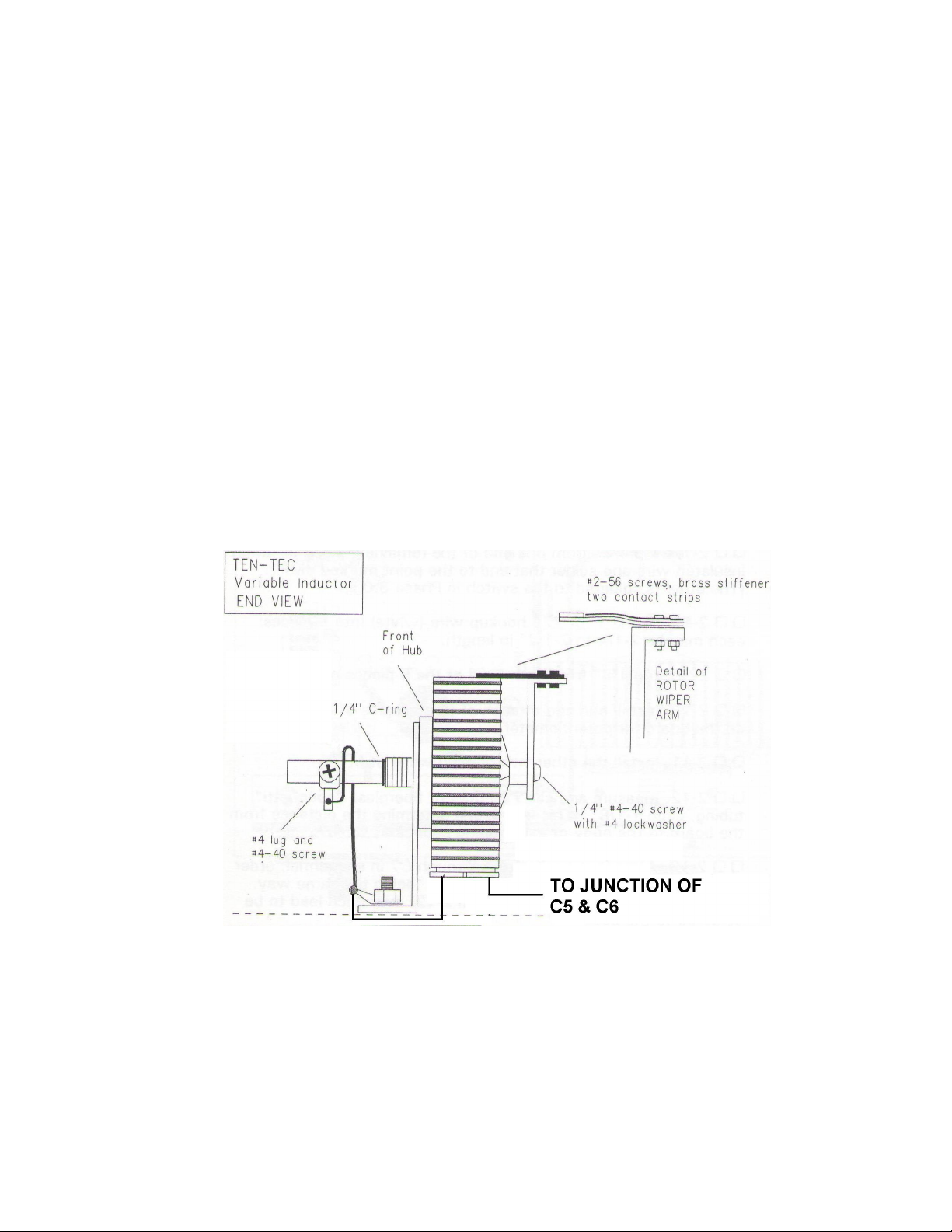
12.□□ Install the variable inductor bracket to the chassis using two 4-40 x 3/8” screws,
nuts and one lockwasher. Place a #4 solder lug on the screw closest to the right hand
side of the chassis, as viewed from the front. See Figure 1 and the drawing below for
reference.
13.□□ Set the inductor wiper to the right (3:00 position) and connect the loose end of
the braid attached to the inductor shaft to the ground lug at the base of the mounting
bracket (NS). Dress the braid as shown on the drawing below.
14.□□ Take the coil pigtail closest to the bracket of the variable inductor and bring it
over to the solder lug where the braid is attached. Connect it to the lug and solder the
lug solidly. (S2)
15.□□ Locate the two variable capacitors, C5 & C6 (they are identical).
16.□□ Locate four 5/8 x 3/8” white fiber shoulder washers, four 3/8” flat washers and
four 3/8” nuts. NOTE: There may be a 3/8” nut and flatwasher already installed on the
shaft of the variable capacitors. If so, remove them.
34 1215 Antenna Tuner Manual Part # 74449
Page 35

17.□□ On each variable capacitor, install a 3/8” nut all the way onto the bushing and
then slide a flatwasher onto the bushing. Take a fiber shoulder washer and slide it on
the bushing so that the raised portion in the center faces away from the capacitor.
18.□□ At the rear of each of the capacitors there will be two solder lugs which point
straight down. Bend each of them upwards against the ceramic so that they point out
the rear of the capacitor.
19.□□ Install the lower variable capacitor “upside down” so that the long solder lug at
the rear end is closest to the bottom of the chassis. Insert the shaft of the capacitor
through the front panel hole and then insert a fiber shoulder washer from the front
followed by a 3/8” flat washer and nut. Ensure that the shoulder washers are seated in
the panel and tighten the front nut securely. As a quick check, using an ohmmeter,
check the resistance from the front panel nut to the chassis. It should show as an
open circuit. If not, loosen the front nut and re-seat the shoulder washers.
20.□□ Install the upper capacitor “right side up” and follow the mounting instructions in
Step 17. Perform the same resistance check.
21.□□ At the rear of the two capacitors are two solder tabs connected to the stator
(stationary) plates of the capacitor. The two tabs for the upper capacitor should almost
be touching the the two tabs for the lower capacitor.
22.□□ Take the free pigtail from the variable inductor and feed it through the upper and
lower stator tabs toward the center of the chassis. Wrap the wire through the tabs and
solder it. (S1) (See Figure 1 for reference)
23.□□ Press the two stator tabs on the outside edge of the chassis together and solder
them. It may help to slightly squeeze the two capacitors together to get the tabs to
touch while soldering. (S0 – No wire connected to this point)
24.□□ Solder the Blue wire from the antenna switch to the rear rotor solder lug of the
lower capacitor. (S1) (See Figure 1 for reference)
25.□□ Solder the Grey wire from the antenna switch to the rear rotor solder lug of the
upper capacitor. (S1) (See Figure 1 for reference)
35 1215 Antenna Tuner Manual Part # 74449
Page 36

FINAL CHASSIS ASSEMBLY
1. □□ Set each of the variable capacitors to maximum capacitance (plates fully
meshed).
2. □□ Locate the two mid-sized knobs and loosen their setscrews and place each on
one of the variable capacitors.
3. □□ With the plates still meshed, rotate the knobs until their pointers point to the “10”
on the scale. Tighten the setscrews.
4. □□ Rotate the variable inductor fully counter-clockwise. Place a large knob on the
shaft and tighten the setscrew with the knob pointing at “0”.
5. □□ Rotate the antenna switch fully counter-clockwise and then clockwise two clicks.
Attach a large knob with the pointer set at “2” and tighten the setscrew.
6. □□ Rotate the SWR SET potentiometer fully counter-clockwise and install a small
knob on it's shaft. Set the pointer to the lower left “dot” on the front panel and tighten
the setscrew.
7. □□ Rotate the Meter Switch fully counter-clockwise and place a small knob on the
shaft. Align the pointer to “SWR” and tighten the setscrew.
8. □□ Locate the jumper bar supplied with the kit. This is used to jumper the “Single
Wire” terminal on the rear panel to the adjacent “Balanced Line” terminal when a balun
is installed inside the 1215. If no balun is installed, this bar can be left jumpering those
two terminals. If a balun is installed and a single wire feed antenna is used, the jumper
must be removed or left hanging on one of the “Balanced Line” terminals so that it
doesn't get misplaced. Hint: Install the bar with the “closed” end on the upper
“Balanced Line” terminal and let it hang down. If left hanging from the “Single
Wire” terminal, it can short against the “Ground” terminal.
9. □□ Install the lamp into the bayonet socket behind the meter.
36 1215 Antenna Tuner Manual Part # 74449
Page 37

PHASE VI: WATTMETER CALIBRATION & CHECKOUT
Required Tools / Equipment:
• Small flat blade screwdriver
• Radio Transmitter capable of providing up to 100 watts or more
• 50 Ohm load capable of handling 100 watts
Calibration of the wattmeter portion of the 1215 Tuner is a straight forward process:
If your radio has a built in wattmeter, proceed directly to Step 1. If the radio does not have a
built in wattmeter, there are two alternatives:
• Connect a calibrated wattmeter between the radio and the tuner. Proceed to Step 1
below.
• Utilize the “Calibration Utilizing DC voltage” procedure at the end of this manual.
1. □□ Connect the 50 Ohm load to the Antenna #1 connector.
2. □□ Connect the radio transmitter to the Radio connector on the 1215
3. □□ Set the 1215 Meter switch to “200 Watts” and select “Bypass”.
4. □□ Key the transmitter on 20 meters and adjust the power to 200 watts, or 100
watts if that is what it is rated at. Use the highest power available for this calibration as
that will produce the most accurate results.
5. □□ Adjust the “200W” pot on the top right of the SWR board so that the wattmeter
reading corresponds to the applied power.
6. □□ Reduce the radio power to 20 watts
7. □□ Set the 1215 Meter switch to “20 Watts”
8. □□ Key the radio and adjust the “20W” pot on the top left of the SWR board so that
the wattmeter reads 20 watts.
9. □□ This completes calibration of the 1215 Tuner wattmeter. Disconnect the radio
and load and install the cover using four 4-40 x 3/16” black flat head screws.
37 1215 Antenna Tuner Manual Part # 74449
Page 38
CALIBRATION USING DC VOLTAGE
If no means of measuring RF power is available, the 1215 wattmeter can be calibrated,
although with reduced accuracy, by injecting a known DC voltage into the “Vf” pad on the
circuit board and adjusting the 20 and 200 watt pots. The transmitter must remain off during
this calibration.
An external DC power supply or a home made DC source can be used to calibrate the
wattmeter.
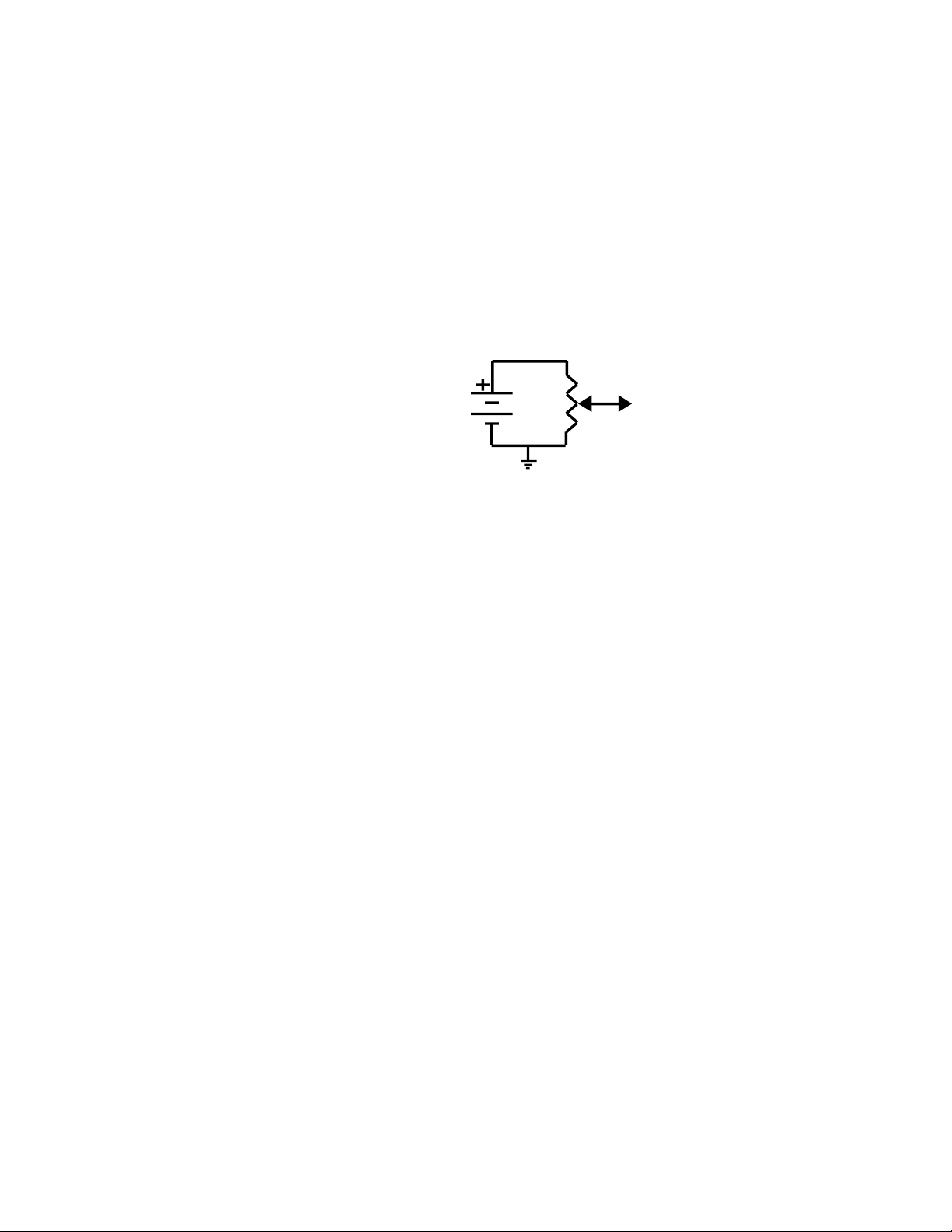
A DC voltage source can be constructed using a 9 volt battery and a 10kΩ potentiometer (not
supplied with the kit) connected as follows:
9V Battery
To “Vf” Pad
Connect the “ground” side to the tuner chassis (a clip lead is a good way to do this). Connect
the wiper of the potentiometer (or the positive output from the variable power supply) to the
“Vf” pad on the circuit board. An easy way to accomplish that is to connect a clip lead from
the wiper of the pot to the banded end (cathode) of diode D1.
Set the meter switch to “200W” and, using a digital voltmeter with the negative lead
connected to the tuner chassis, adjust the voltage at the “Vf” pad to 5.80 volts. Adjust the
“200W” pot on the upper right of the SWR circuit board until the meter reads 200 watts.
Reduce the DC voltage at the “Vf” pad to 1.70 volts and switch the meter to the “20W” scale.
Re-check the DC voltage after switching scales and readjust if necessary. Adjust the “20W”
pot on the top left of the SWR board for a reading of 20 watts.
Remove the DC voltage source. The calibration is complete.
This completes calibration of the 1215 Tuner wattmeter. Disconnect the radio and load and
install the cover using eight 4-40 x 1/4” black flat head screws.
38 1215 Antenna Tuner Manual Part # 74449
Page 39

OPERATIONAL TEST
This is a quick functional test to ensure that the 1215 is wired correctly and functioning
normally. For this test, use one of your actual antennas and select a frequency where the
SWR is greater than 1:1.
1. Connect your radio to the “RADIO” port on the rear of the tuner.
2. Connect an antenna to the “ANT 1” port on the rear of the tuner.
3. Set the meter switch to “200W” and the Antenna switch to “BYPASS”
4. Key the radio – all indications should be the same as they were before the tuner was
installed since the radio is connected directly to the antenna on the “ANT 1” port.
5. Set the meter switch to “SET” and key the transmitter in the CW mode.
6. Adjust the “SWR SET” pot for a full scale meter reading.
7. Change the meter switch to “SWR” and note the SWR reading on the meter.
8. Reduce the transmitter power to approximately 20 watts and de-key it.
9. Change the Antenna switch to the “ANT 1” position.
10.Perform the tuning procedure as described in the “OPERATING TIPS” section of this
manual (Page 12).
11. If the tuning procedure is successful, move your antenna to the “ANT 2” connector,
change the Antenna switch to “ANT 2” and check to see that everything is working as it
was with the antenna connected to the “ANT 1” port.
12.Repeat Step 11 for antenna ports 3 and 4.
If any difficulties are encountered during this check-out, re-check all of the wiring for accuracy
and ensure that all connections are soldered. If the Wattmeter / SWR functions worked
correctly during the test in the “BYPASS” position, then there are no problems with the SWR
Board, the wiring of the meter switch or the “Set” pot.
If the tuner works on some, but not all, positions of the “ANTENNA” switch, check the wiring
of that switch. Use the “Troubleshooting Chart” section of the manual (Page 13) to aid in
locating any problems.
39 1215 Antenna Tuner Manual Part # 74449
Page 40
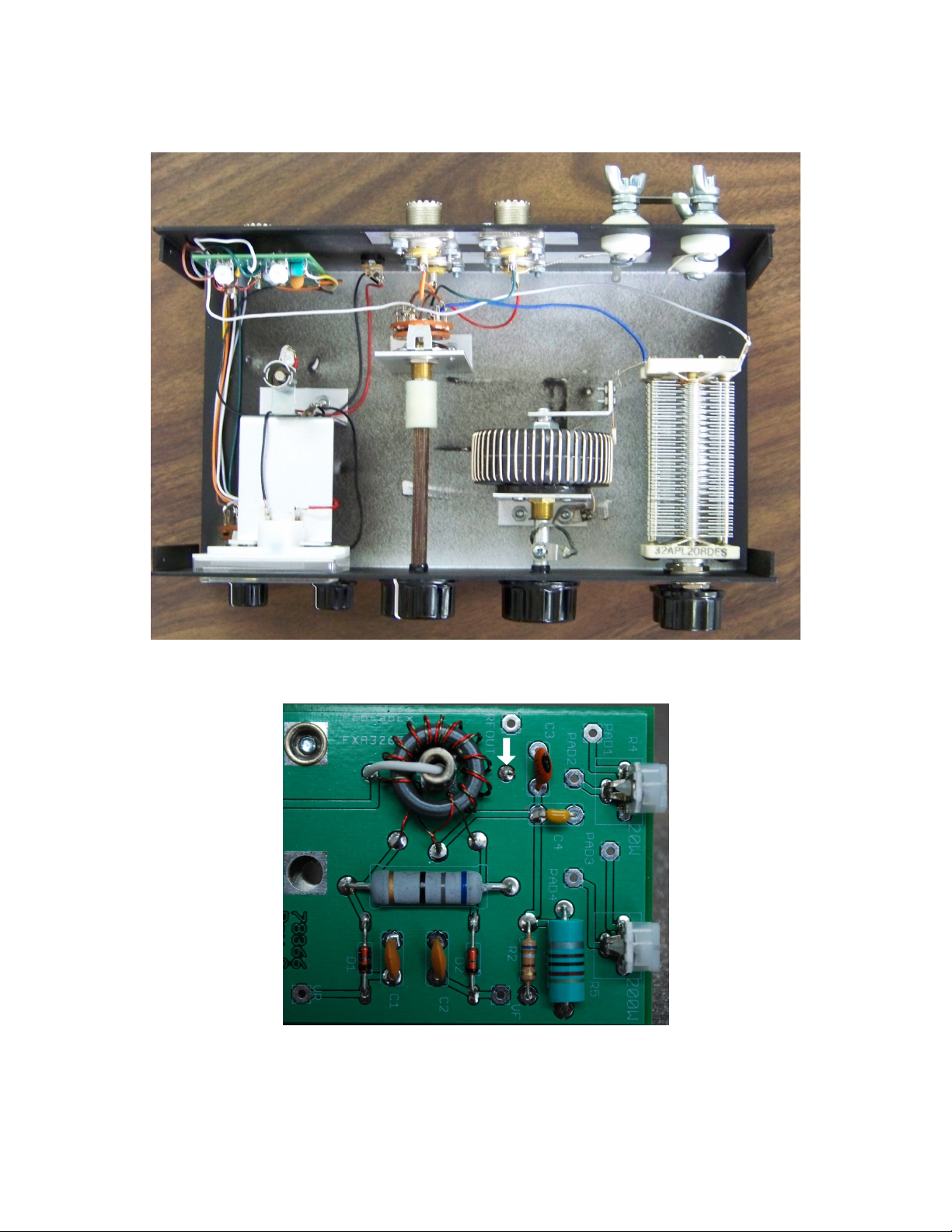
APPENDIX
FIGURE 1 – TOP VIEW OF TUNER
FIGURE 2 – SWR BOARD LAYOUT
40 1215 Antenna Tuner Manual Part # 74449
Page 41
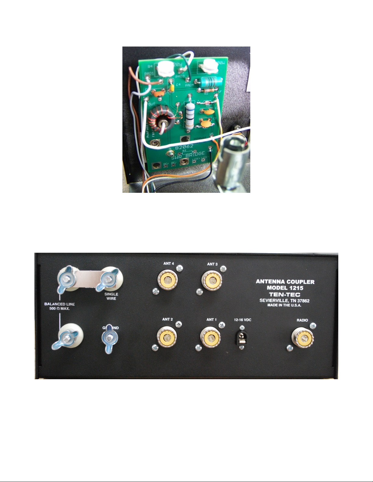
FIGURE 4 – SWR BRIDGE WIRING
FIGURE 5 – REAR PANEL
41 1215 Antenna Tuner Manual Part # 74449
Page 42

TEN-TEC KIT LIMITED WARRANTY
Please read carefully BEFORE building your kit.
This Limited Warranty applies solely to kits sold by TEN-TEC, Inc. The terms of this Warranty do not
apply to other products of any kind manufactured by TEN-TEC, Inc., nor shall any other warranties
published by TEN-TEC, Inc., or any TEN-TEC customer service policies for its manufactured products,
be construed as applicable to kit products.
1. All components and hardware supplied as parts of a kit are warranted to be free from manufacturing
defects for one year from date of purchase.
2. The original purchaser has the option of examining the kit and manual for 30 days. If you choose within
this period not to construct the kit, you may return the entire unassembled kit at your own expense for
full credit toward any other TEN-TEC product, or a refund, less original shipping / handling charges,
providing that the parts package(s) have not been opened.
3. This warranty is void if acid-core solder is used in construction. Use ROSIN CORE solder only, of a
grade designed for electronic PC-board assembly.
4. TEN-TEC, Inc. warrants this device to function as described in its documentation provided that it is
assembled and used correctly in accord with all printed directions. It is your responsibility to follow all
directions in the instruction manual, to identify components correctly and to use good workmanship and
proper tools in constructing this kit.
5. We do not accept the return of partially-assembled kits for refund.
6. If you believe a kit part is missing, do a thorough sorting of all parts, checking each off on the parts list in
the manual. Check all bags, boxes and envelopes carefully. Simply call, email or FAX our service
department at (865) 428-0364 (Voice), ([email protected]) or (865) 428-4483 (FAX) and we will
promptly replace any missing part.
7. If your kit does not work after final assembly, please follow these steps:
1. Double check every step in the assembly manual and any troubleshooting tips provided.
2. If the above does not resolve the issue, contact the TEN-TEC service department at (865) 428-0364
or via email at [email protected]
8. Factory Inspection or Service: If you wish to return a kit for professional inspection or repair, simply
send your kit along with a note explaining the problem. Please include a daytime phone number and
email address. Charges for repairs will be at the prevailing shop rate. A Return Authorization is not
required prior to sending a product in for repair. If we find that a part was defective in manufacture, there
will be no charge to repair your kit. Our technicians will make the determination whether a part was
defective in manufacture or was damaged during installation. We recommend calling our service
department first to see if the problem can be resolved over the phone.
9. TEN-TEC, Inc. reserves the right to revise this Limited Warranty, to change or discontinue any kit
product or revise its instruction manual with no liability to previous purchasers.
10. TEN-TEC, Inc., is not liable for any consequences from use or abuse of any kit or part contained therein.
TEN-TEC, INC.
1185 Dolly Parton Parkway
Sevierville, TN 37862
(865) 453-7172
www.tentec.com
42 1215 Antenna Tuner Manual Part # 74449
 Loading...