

Tennant 275 II User Manual

r
Home
Find...
Go To..
(Operator Manual)
275 Series II
Sweeper/
Scrubber

r
Home
Find...
Go To..
This manual is furnished with each new TENNANTr Model 275 Series II. It provides necessary operating and
preventive maintenance instructions. Read this manual completely and understand the machine before
operating or servicing it.
This manual covers all machine variations and standard accessories. The tabbed instruction portion of the
manual consists of the Specification, Operation, Maintenance, and Appendix sections. The tabbed parts section
consists of the Low Dump Model Parts; Diesel Parts; Multi-Level Dump Model Parts; Accessories; Hydraulic
Components; Engine Parts, Gasoline, LPG; and Engine Parts, Diesel sections. The tabbed Cross Reference
section identifies the page numbers on which each of the part numbers listed in the manual can be found.
All right side and left side references to the machine are determined by facing the direction of forward travel. All
hardware considered to be of a common nature or locally available has been omitted from the parts sections.
Be aware that this machine may contain metric hardware. Make sure you use equivalent hardware when
replacement becomes necessary.
This machine will provide excellent service. However, the best results will be obtained at minimum costs if:
D The machine is operated with reasonable care.
D The machine is maintained regularly --- per the maintenance instructions provided.
D The machine is maintained with Tennant Company supplied or equivalent parts.
Parts and supplies may be ordered by phone or mail from any Tennant Company parts and service center,
distributor, or from any of the Tennant Company subsidiaries. Before ordering parts or supplies, be sure to have
your machine model number and serial number handy. Fill out the data block below for future reference. The
telephone numbers, telex numbers, mailing addresses, and locations of those outlets are listed in the Customer
Documents section of the manual.
MACHINE DATA
Please fill out at time of installation.
Machine Serial Number ---
Engine Serial Number ---
Sales Representative ---
Date of Installation ---
Manual Number --- MM190
Revision: 05
Published: 6---90
Trademark Registered in: Austria, Benelux, Denmark, England, France, Germany, Italy, Spain, Switzerland,
United States, Argentina, Australia, Canada, Japan, Mexico, Sweden, by TENNANT COMPANY, Minneapolis,
Minnesota, U.S.A.
04632
Acknowledgements: Technical information and/or illustrations supplied by Ford Motor Company; Kubota Ltd.;
Cessna Fluid Power Division; Eaton Corporation, Hydraulics Division.
Copyright 1987, 1988, 1989, 1990 Tennant Company, Printed in U.S.A.

ABOUT THIS MANUAL
Home
Find...
Go To..
ABOUT THIS MANUAL
The machine manual that you received with your
TENNANT machine contains valuable information
about the operation and maintenance, and
numerous sections filled with TENNANT part
numbers for the repair of the machine. Please read
through this section titled ABOUT THIS MANUAL to
become familiar with the contents of the machine
manual, making the information you are looking for
easier to find.
The machine manual consists of several sections of
reference information, and the remainder contain
part number information for ordering repair parts for
the machine. Each section has a shaded bar at the
top of the page with the name of that section. Just as
this section has the title ABOUT THIS MANUAL on
the top of each page. This way you can tell which
section you are in at all times.
REFERENCE SECTIONS
The reference information sections of the manual
are; General Information, Specifications, Operation,
Maintenance, and Appendix.
GENERAL INFORMATION --- The General Information
section of the manual contains the safety
precautions, the location of the safety labels on the
machine, and a table of contents of the entire
manual. The Safety Precautions are an overview of
the safety measures to be observed when operating
and maintaining your machine. The location of the
safety labels show the mounting location of the
safety labels for use in the replacement of the labels.
The table of contents in this section is a list of all the
table of contents that appear in the front of each
section in the manual. This can be used for easy
reference to locate information in a particular section
of the manual.
SPECIFICATIONS --- The Specifications section of the
manual contains machine specification information
useful in the operation and maintenance of the
machine. This section gives you specification
information on the engine, electric motors, brake
system, hydraulics, fluid capacities, and machine
weight to mention a few. The section also has a
illustration of the top and side view of the machine
with the height and width dimensions displayed.
OPERATION --- The Operation section of the manual
contains information needed to operate the machine.
This section will list the controls and instruments on
the machine, overview the machine operation, and
tell you how to transport and store the machine.
MAINTENANCE --- The Maintenance section contains
information on the suggested maintenance
procedures and adjustments to keep your machine
in top operating condition. The section includes a
Maintenance Chart listing the maintenance schedule
and the areas of the machine to be addressed. Each
subject of maintenance is covered in more detail in
such areas as Lubrication, Hydraulics, Engine, and
Electrical System.
APPENDIX --- The Appendix contains hardware and
hydraulic information. Standard hardware torques
and identification information is included, plus
hydraulic torques if your machine is hydraulically
controlled.
PART SECTIONS
The remaining sections of the manual contain part
number information for ordering repair parts for your
machine. The manual contains part number
information on every type of machine model
available in the model size of your particular
machine. Therefore there will be part number
information in your manual you will not need to refer
to when wanting to place an order.
The main thing you need to know about your
machine is what type of model is it. Is the machine
powered by an engine or batteries? If the machine
has an engine, is it fueled from gasoline, LPG, or
gasoline? If it is a mid-sized or larger sweeper, is it
multi-level or low dump? For the scrubbers, is it
SRSr or standard. Determining this information
about your machine will help guide you through the
separate parts sections to find the repair part you
need.
275 SERIES II MM190 (12 ---89)
a

ABOUT THIS MANUAL
Home
Find...
Go To..
The smaller line of sweeper and scrubbers have less
complicated part section arrangement, and are
easier to find your way through the parts sections.
The larger machines can have quite a variety of
model types which significantly increases the size to
the machine manual. Because of this, on the larger
machine we made the first part section, Section 5, a
part section which contains parts common to all type
of the machine. If the machine has an engine, this
section contains parts information on a gasoline
powered machine.
The remaining sections contain only parts
information which is unique to that particular
machine type, such as unique diesel parts on the
machine, or unique SRSr parts. Knowing the
machine model type you have is important when
searching for that part information you need for
ordering repair parts. Start in that unique section first
when looking for a part, then go to the first parts
section, Section 5, if the part can’t be found in the
unique section.
MACHINE SERIAL NUMBERS
When a design change takes place to a machine,
the changes are indicated in the parts sections with
machine serial numbers. Know the serial number of
your machine which can be found on the machine
data plate mounted on the machine. Record this
number on the inside front cover of your manual
along with your customer number.
Machine number usage is recorded in the Machine
Serial Number column of the parts lists in the parts
sections of the manual. If the machine serial number
column lists zeros on the left side of the dash, then
this part is used on all machines; such as (000000---
).
For parts that are used on machines beginning at
and continuing on from a certain serial number, the
column would list a serial number on the left of the
dash and have blank spaces on the right side of the
dash; such as (002346--- ). This part would be
used on machines starting with that machine serial
number and greater.
Finally, parts can be used on machines with serial
numbers in a certain block of numbers. In this
situation there is a serial number on the left and right
side of the dash. The part is then used on a machine
with a serial number starting at the number on the
left and up to and including the number on the right;
such as (002346---008900).
PARTS ASSEMBLIES
A part assembly has parts within the assembly, such
as a parking brake consisting of other smaller parts.
What parts are contained in a part assembly can be
determined by an indentation arrangement in the
description column of the parts lists.
Here is an example of a part assembly, in this case
we will use the parking brake mentioned previously:
Machine
Serial Number Description Qty.
(000000--- ) Parking Brake 1
(000000--- ) Pin, Roll 1
(000000--- ) Link 1
(000000--- ) Spring, Compression 1
(000000--- ) Pin, Roll 1
(000000--- ) Support 1
(000000--- ) Lever, Release 1
(000000--- ) Rod, Parking Brake 1
(000000--- ) Washer, 0.50” 3
If the column lists zeros on the left of the dash and a
number on the right of the dash, then the part is
used on machines up to and including that machine
serial number; such as (00000---002345).
b
In this example, the parts whose descriptions are
indented under the parking brake are all parts of the
parking brake. When you order the parking brake
you will receive all the parts listed under it. You also
can order any of the individual parts listed under the
parking brake if it is the only part you need.
275 SERIES II MM190 (12 ---89)

SUPPLIER COMPONENT BREAKDOWNS
Home
Find...
Go To..
TENNANT purchases certain components of the
machine from suppliers. Some of these components
are engines, hydraulic pumps and motors, electric
motors, and solution pumps.
For those purchased components that are
repairable, lists of parts for them appear in the later
part of the parts sections. These are the supplier
breakdowns. The engine breakdown contains both
supplier and TENNANT parts numbers for repair
parts. Breakdowns for hydraulic and electrical
components have TENNANT part numbers for the
parts TENNANT supplies. The serial numbers listed
in any of the parts lists in these sections is a serial
number the manufacturer uses to identify design
changes in their particular component.
ORDERING REPAIR PARTS
Once you have located a part to order, there are
several things you need to have to place the order.
At the beginning of each parts section is an Ordering
Repair Parts page which lists the information you will
need to place your order. Review this list before
placing the order.
ABOUT THIS MANUAL
275 SERIES II MM190 (12 ---89)
c

ABOUT THIS MANUAL
Home
Find...
Go To..
d
275 SERIES II MM190 (12 ---89)
SAFETY PRECAUTIONS
Home
Find...
Go To..
GENERAL INFORMATION
The following symbols are used throughout this
manual as indicated in their descriptions:
WARNING: To warn of hazards or unsafe
practices which could result in severe
personal injury or death.
FOR SAFETY: To identify actions which must be
followed for safe operation.
The following information signals potentially
dangerous conditions to the operator or equipment.
Read this manual carefully. Know when these
conditions can exist. Locate all safety devices on the
machine. Then take necessary steps to train
machine operating personnel. Report machine
damage or faulty operation immediately. Do not use
the machine if it is not in proper operating condition.
FOR SAFETY:
1. Do not operate machine:
-- Unless trained and authorized.
-- Unless operation manual is read and
understood.
-- In flammable or explosive areas unless
modified for use in those areas.
-- In areas with possible falling objects
unless equipped with overhead guard.
2. Before starting machine:
-- Check for fuel leaks (gasoline, LPG,
diesel).
-- Make sure all safety devices are in
place and operate properly. See
Operation section.
-- Check brakes and steering for proper
operation.
5. Before leaving or servicing machine:
-- Stop on level surface.
-- Set parking brake.
-- Turn off machine and remove key.
6. When servicing machine:
-- Avoid moving parts. Do not wear loose
jackets, shirts, or sleeves when working
on machine.
-- Use Tennant Company supplied or
equivalent replacement parts.
WARNING: Machine emits toxic gases.
Severe respiratory damage or asphyxiation
can result. Provide adequate ventilation. Consult
with your regulatory agency for exposure limits.
Keep engine properly tuned.
WARNING: Brush throws debris. Severe
personal injury can result. Stop motor
before lifting hopper.
WARNING: Machine can emit excessive
noise. Consult with your regulatory agency
for exposure limits. Hearing loss can result. Wear
hearing protection.
WARNING: Machine hopper lifts to 108 in
(2745 mm) when high dumping. Hopper can
hit overhead wires or object. Electrical shock or
falling debris can result. Be sure adequate
clearance is available before raising hopper.
WARNING: Machine can have static
electricity charge. When pouring fuel, spark
can ignite fuel causing fire or explosion. Connect
wire attached to fuel can to machine to discharge
spark before pouring fuel.
3. When starting machine:
-- Keep foot on brake and directional
pedal in neutral.
4. When using machine:
-- Go slow on grades and slippery
surfaces.
-- Use care when backing machine.
-- Do not carry riders on machine.
-- Always follow safety and traffic rules.
275 SERIES II MM190 (12---89)
WARNING: Machine moves when
directional pedal linkage is out of
adjustment. Severe personal injury or death can
result. If machine creeps when the directional
pedal is in neutral, adjust pedal linkage. Engage
parking brake when stopped.
WARNING: Falling hopper. Engage hopper
support bar before working under hopper.
i
GENERAL INFORMATION
Home
Find...
Go To..
WARNING: Fuel vapor is present when
servicing fuel system. Fire or explosion can
result. Keep flames and sparks away.
WARNING: Hot engine coolant. Scalding
can result. Do not open radiator cap or
service cooling system until radiator and engine
is cool to the touch.
WARNING: Flammable materials can
cause an explosion or fire. Do not use
flammable materials in solution tank.
WARNING: The solution and recovery tanks
must be empty during scrub attachment
installation and removal to avoid personal injury.
WARNING: Machine is unstable on jack.
Jack machine up at designated locations
only. Block machine up with jack stands.
WARNING: Machine is unstable on jack.
Block machine tires before jacking machine
up.
WARNING: Leaking hydraulic fluid under
pressure can penetrate skin. Severe
infection or death can result. Do not use body to
locate leak. Use cardboard to locate leak.
WARNING: Air or water under pressure.
Severe eye or ear injury can result. Wear
eye and ear protection.
WARNING: LPG fuel is very cold. Frostbite
can result. Wear gloves when connecting or
disconnecting LPG hoses.
WARNING: Battery acid causes severe
burns. Avoid contact. Wash immediately
and get medical attention if contact occurs.
WARNING: Stay clear of hopper lift arms
when they are in motion.
WARNING: Keep away from fan.
ii
275 SERIES II MM190 (12---89)
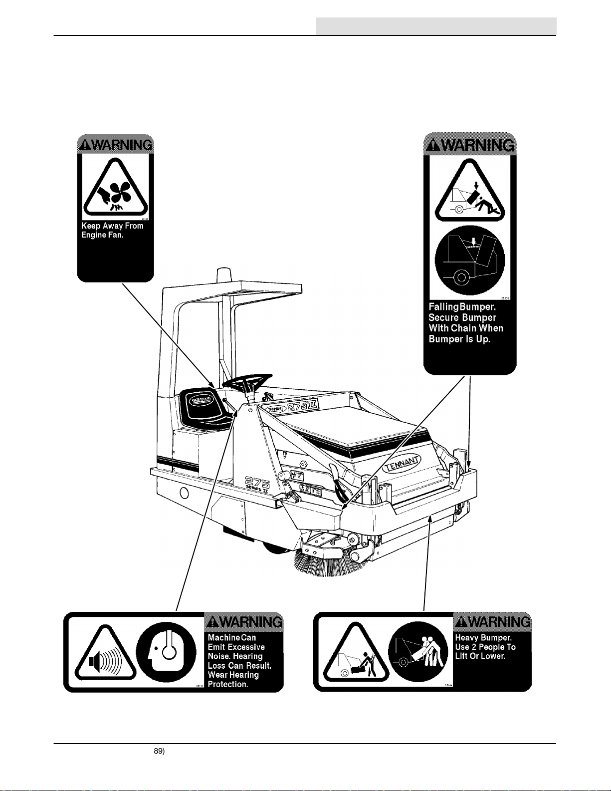
The following safety labels are mounted on the
Home
Find...
Go To..
machine in the locations indicated. If these, or any,
labels become damaged or illegible, install a new
label in its place.
ENGINE FAN LABEL -- LOCATED ON ENGINE
FAN SHROUD.
GENERAL INFORMATION
BUMPER CHAIN LABEL -- LOCATED ON
UNDERSIDE OF BUMPER, LOW DUMP MODEL
ONLY.
NOISE LABEL -- LOCATED ON FRONT RIGHT OF
OPERATOR COMPARTMENT.
275 SERIES II MM190 (12---89)
02745
HEAVY BUMPER LABEL -- LOCATED ON
UNDERSIDE OF BUMPER, LOW DUMP MODEL
ONLY.
iii
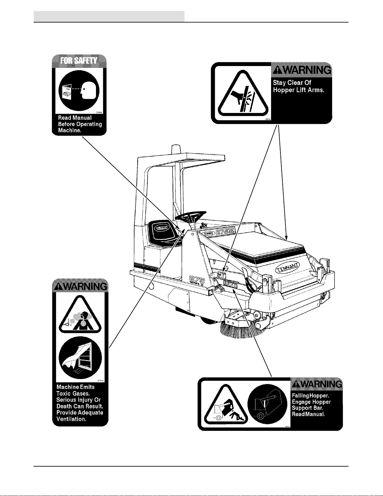
GENERAL INFORMATION
Home
Find...
Go To..
FOR SAFETY LABEL -- LOCATED ON LEFT SIDE
OF OPERATOR COMPARTMENT.
HOPPER LIFT ARMS LABEL -- LOCATED ON
HOPPER LIFT ARMS, MULTI-LEVEL DUMP
MODEL ONLY.
EMISIONS LABEL -- LOCATED ON LEFT SIDE OF
OPERATOR COMPARTMENT.
iv
02745
HOPPER SUPPORT BAR LABEL -- LOCATED ON
HOPPER SUPPORT BAR.
275 SERIES II MM190 (12---89)

CONTENTS
Home
Find...
Go To..
GENERAL INFORMATION
Page
GENERAL INFORMATION i. . . . . . . . . . . . . . . . . . . . .
SAFETY PRECAUTIONS i. . . . . . . . . . . . . . . . . . .
SPECIFICATIONS 1-1. . . . . . . . . . . . . . . . . . . . . . . . . .
MACHINE SPECIFICATIONS 1-3. . . . . . . . . . . . .
POWER TYPE 1-3. . . . . . . . . . . . . . . . . . . . . . .
POWER TRAIN 1-3. . . . . . . . . . . . . . . . . . . . . .
STEERING 1-3. . . . . . . . . . . . . . . . . . . . . . . . . .
HYDRAULIC SYSTEM 1-3. . . . . . . . . . . . . . . .
BRAKING SYSTEM 1-4. . . . . . . . . . . . . . . . . .
SUSPENSION SYSTEM 1-4. . . . . . . . . . . . . . .
SYSTEM FLUID CAPACITIES 1-4. . . . . . . . .
GENERAL MACHINE
DIMENSIONS/CAPACITIES 1-4. . . . . . . . .
MACHINE WEIGHTS 1-4. . . . . . . . . . . . . . . . . .
GENERAL MACHINE PERFORMANCE 1-4. .
MACHINE DIMENSIONS 1-5. . . . . . . . . . . . . . . . .
OPERATION 2-1. . . . . . . . . . . . . . . . . . . . . . . . . . . . . . .
OPERATION 2-1. . . . . . . . . . . . . . . . . . . . . . . . . . . .
PREPARATION FOR OPERATION 2-3. . . . . . . .
AFTER UNLOADING AND BEFORE
OPERATING THE MACHINE: 2-3. . . . . . .
OPERATION OF CONTROLS 2-4. . . . . . . . . . . .
MACHINE COMPONENTS ---
MULTI-LEVEL DUMP
MODEL SHOWN 2-4. . . . . . . . . . . . . . . . .
INSTRUMENT PANEL SYMBOLS 2-5. . . . . .
CONTROLS AND INSTRUMENTS 2-7. . . . .
BRAKE PEDAL 2-8. . . . . . . . . . . . . . . . . . . . . .
DIRECTIONAL PEDAL 2-8. . . . . . . . . . . . . . .
PARKING BRAKE LEVER 2-8. . . . . . . . . . . . .
OPERATOR SEAT 2-8. . . . . . . . . . . . . . . . . . .
SQUEEGEE SWITCH 2-8. . . . . . . . . . . . . . . .
WATER VALVE SWITCH 2-8. . . . . . . . . . . . . .
FUEL LEVEL GAUGE 2-8. . . . . . . . . . . . . . . .
THROTTLE LEVER 2-8. . . . . . . . . . . . . . . . . .
THROTTLE SWITCH 2-9. . . . . . . . . . . . . . . . .
HAZARD LIGHT SWITCH 2-9. . . . . . . . . . . . .
ENGINE CHOKE KNOB 2-9. . . . . . . . . . . . . .
DRIVE LIGHTS SWITCH 2-9. . . . . . . . . . . . . .
DIESEL PREHEAT PUSHBUTTON
AND INDICATOR 2-9. . . . . . . . . . . . . . . . .
HOPPER DUMP LEVER 2-9. . . . . . . . . . . . . .
HOPPER LIFT AND SIDE BRUSH LEVER 2-9
MAIN BRUSH POSITION LEVER 2-10. . . . . .
MAIN BRUSH HEIGHT
ADJUSTMENT KNOB 2-10. . . . . . . . . . . . .
STEERING WHEEL 2-10. . . . . . . . . . . . . . . . . .
Page
MAIN BRUSH, VACUUM FAN
AND FILTER SHAKER SWITCH 2-10. . . . .
CLOGGED FILTER LAMP 2-10. . . . . . . . . . . . .
ENGINE HOUR METER 2-10. . . . . . . . . . . . . .
ENGINE COOLANT
TEMPERATURE GAUGE 2-11. . . . . . . . . . .
ENGINE OIL PRESSURE GAUGE 2-11. . . . .
BATTERY CONDITION GAUGE 2-11. . . . . . . .
IGNITION SWITCH 2-11. . . . . . . . . . . . . . . . . . .
SIDE BRUSH POSITION LEVER 2-11. . . . . . .
HOPPER SUPPORT BAR 2-11. . . . . . . . . . . . .
TO ENGAGE HOPPER
SUPPORT BAR 2-11. . . . . . . . . . . . . . . .
TO DISENGAGE HOPPER
SUPPORT BAR 2-12. . . . . . . . . . . . . . . .
SCRUB BRUSH POSITION LEVER 2-13. . . . .
SOLUTION FLOW KNOB 2-13. . . . . . . . . . . . .
CIRCUIT BREAKERS 2-13. . . . . . . . . . . . . . . .
MACHINE OPERATION 2-14. . . . . . . . . . . . . . . . .
NORMAL SWEEPING OPERATION 2-14. . . .
PRE-START CHECKLIST 2-14. . . . . . . . . .
TO START MACHINE 2-14. . . . . . . . . . . . .
TO SWEEP 2-15. . . . . . . . . . . . . . . . . . . . . .
POST OPERATION CHECKLIST ---
ENGINE OPERATING 2-16. . . . . . . . . .
TO STOP MACHINE 2-16. . . . . . . . . . . . . .
POST OPERATION CHECKLIST ---
ENGINE STOPPED 2-16. . . . . . . . . . . .
NORMAL SCRUBBING OPERATION 2-17. . .
PRE-START CHECKLIST 2-17. . . . . . . . . .
TO START MACHINE 2-17. . . . . . . . . . . . .
TO SCRUB 2-18. . . . . . . . . . . . . . . . . . . . . .
TO DRAIN RECOVERY TANK
AND EMPTY DEBRIS HOPPER 2-18. .
POST OPERATION CHECKLIST ---
ENGINE OPERATING 2-19. . . . . . . . . .
TO STOP MACHINE 2-19. . . . . . . . . . . . . .
POST OPERATION CHECKLIST ---
ENGINE STOPPED 2-19. . . . . . . . . . . .
DOUBLE SCRUBBING OPERATION 2-20. . .
OPERATION ON GRADES 2-20. . . . . . . . . . . .
VACUUM WAND 2-20. . . . . . . . . . . . . . . . . . . .
TO OPERATE VACUUM WAND 2-20. . . . .
HOPPER DOLLY 2-21. . . . . . . . . . . . . . . . . . . . .
TO REMOVE HOPPER WITH DOLLY 2-21
TO INSTALL HOPPER WITH DOLLY 2-22.
SCRUB ATTACHMENT 2-23. . . . . . . . . . . . . . .
TO MOUNT SCRUB ATTACHMENT 2-23.
TO REMOVE SCRUB ATTACHMENT 2-26
SNOW BLADE 2-27. . . . . . . . . . . . . . . . . . . . . .
TO INSTALL SNOW BLADE 2-27. . . . . . . .
TO OPERATE SNOW BLADE 2-28. . . . . . .
275 SERIES II MM190 (12---89)
v

GENERAL INFORMATION
Home
Find...
Go To..
TO REMOVE SNOW BLADE 2-29. . . . . . .
SNOW BROOM 2-30. . . . . . . . . . . . . . . . . . . . .
TO INSTALL SNOW BROOM
ASSEMBLY 2-30. . . . . . . . . . . . . . . . . . .
TO OPERATE SNOW BROOM 2-32. . . . . .
MACHINE TROUBLESHOOTING ---
SWEEPING 2-34. . . . . . . . . . . . . . . . . . . . . .
MACHINE TROUBLESHOOTING ---
SCRUBBING 2-35. . . . . . . . . . . . . . . . . . . . .
TRANSPORTING MACHINE 2-36. . . . . . . . . . . . .
PUSHING OR TOWING MACHINE 2-36. . . . .
MACHINE JACKING 2-36. . . . . . . . . . . . . . . . .
TO JACK UP MACHINE 2-36. . . . . . . . . . .
MACHINE TIE-DOWNS 2-37. . . . . . . . . . . . . . .
MACHINE STORAGE 2-38. . . . . . . . . . . . . . . . . . .
STORING MACHINE 2-38. . . . . . . . . . . . . . . . .
MAINTENANCE 3-1. . . . . . . . . . . . . . . . . . . . . . . . . . .
RECOMMENDED FIRST 50-HOUR
MACHINE INSPECTION 3-3. . . . . . . . . . . . . .
MAINTENANCE CHART 3-4. . . . . . . . . . . . . . . . .
LUBRICATION 3-6. . . . . . . . . . . . . . . . . . . . . . . . .
ENGINE 3-6. . . . . . . . . . . . . . . . . . . . . . . . . . . .
GASOLINE AND LPG POWERED
ENGINES 3-6. . . . . . . . . . . . . . . . . . . . .
DIESEL POWERED ENGINES 3-6. . . . . .
STEERING GEAR 3-6. . . . . . . . . . . . . . . . . . .
REAR WHEEL SUPPORT 3-6. . . . . . . . . . . . .
FRONT WHEEL BEARINGS 3-6. . . . . . . . . . .
HOPPER LIFT ARM PIVOTS 3-7. . . . . . . . . .
HOPPER DOOR LATCHES 3-7. . . . . . . . . . . .
SCRUB ATTACHMENT LEG CASTERS 3-8.
SCRUB ATTACHMENT DEBRIS HOPPER 3-8
HYDRAULICS 3-9. . . . . . . . . . . . . . . . . . . . . . . . . .
HYDRAULIC FLUID 3-9. . . . . . . . . . . . . . . . . .
HYDRAULIC FLUID RESERVOIR 3-9. . . . . .
TO DRAIN HYDRAULIC FLUID
RESERVOIR AND REPLACE
FILTER ELEMENT 3-10. . . . . . . . . . . . . .
TO FILL HYDRAULIC FLUID
RESERVOIR 3-11. . . . . . . . . . . . . . . . . .
HYDRAULIC PUMPS 3-11. . . . . . . . . . . . . . . . .
DIRECTIONAL PEDAL 3-11. . . . . . . . . . . . . . .
TO ADJUST DIRECTIONAL PEDAL 3-12.
LIFT ARM SPEED LIMITER 3-13. . . . . . . . . . .
HYDRAULIC FLUID LEAKS 3-13. . . . . . . . . . .
HYDRAULIC SCHEMATIC,
LOW DUMP MODEL 3-14. . . . . . . . . . . . . .
HYDRAULIC SCHEMATIC,
MULTI-LEVEL DUMP MODEL 3-15. . . . . .
HYDRAULIC SYSTEM
TROUBLESHOOTING 3-16. . . . . . . . . . . . .
HYDRAULIC COMPONENTS
TROUBLESHOOTING 3-18. . . . . . . . . . . . .
ENGINE 3-19. . . . . . . . . . . . . . . . . . . . . . . . . . . . . . .
ENGINE LUBRICATION 3-19. . . . . . . . . . . . . .
Page
Page
GASOLINE AND LPG
POWERED ENGINES 3-19. . . . . . . . . .
DIESEL POWERED ENGINES 3-19. . . . . .
COOLING SYSTEM 3-19. . . . . . . . . . . . . . . . . .
AIR INTAKE SYSTEM 3-20. . . . . . . . . . . . . . . .
AIR FILTER RESTRICTION
INDICATOR 3-20. . . . . . . . . . . . . . . . . . .
AIR FILTER 3-21. . . . . . . . . . . . . . . . . . . . . .
TO REPLACE AIR FILTER ELEMENT 3-21
FUEL SYSTEM --- GASOLINE 3-23. . . . . . . . .
FUEL FILTER 3-23. . . . . . . . . . . . . . . . . . . . .
CARBURETOR 3-23. . . . . . . . . . . . . . . . . . .
FUEL SYSTEM --- LPG 3-23. . . . . . . . . . . . . . .
LPG FUEL SYSTEM 3-23. . . . . . . . . . . . . . .
FUEL TANKS 3-24. . . . . . . . . . . . . . . . . . . . .
TO CHANGE AN LPG FUEL TANK 3-25. .
FUEL FILTER LOCK 3-26. . . . . . . . . . . . . . .
VAPORIZER-REGULATOR 3-26. . . . . . . . .
CARBURETOR 3-26. . . . . . . . . . . . . . . . . . .
OIL PRESSURE SWITCH 3-26. . . . . . . . . .
LPG FUEL TROUBLESHOOTING 3-27. . .
FUEL SYSTEM --- DIESEL 3-28. . . . . . . . . . . .
DIESEL FUEL SYSTEM 3-28. . . . . . . . . . . .
FUEL WATER TRAP-FILTER 3-28. . . . . . . .
TO REPLACE FUEL FILTER
ELEMENT 3-28. . . . . . . . . . . . . . . . . . . .
PRIMING FUEL SYSTEM 3-29. . . . . . . . . .
TO PRIME FUEL SYSTEM 3-29. . . . . . . . .
GOVERNOR --- GASOLINE, LPG
(For machines below serial
number 006500) 3-29. . . . . . . . . . . . . . . . . .
TO ADJUST GOVERNOR
(For machines below serial
number 006500) 3-30. . . . . . . . . . . . . . .
GOVERNOR --- GASOLINE, LPG
(For machines serial number
006500 and above) 3-30. . . . . . . . . . . . . . .
IGNITION SYSTEM --- GASOLINE, LPG 3-30.
SPARK PLUGS 3-30. . . . . . . . . . . . . . . . . . .
DISTRIBUTOR
(For machines below serial
number 006500) 3-31. . . . . . . . . . . . . . .
ENGINE IGNITION TIMING
(For machines below serial
number 006500) 3-31. . . . . . . . . . . . . . .
TO CHECK AND ADJUST IGNITION
TIMING (For machines below
serial number 006500) 3-31. . . . . . . . . .
ENGINE IGNITION TIMING
(For machines serial
number 006500 and above) 3-32. . . . .
CYLINDER HEAD --- GASOLINE, LPG 3-32. .
CYLINDER HEAD 3-32. . . . . . . . . . . . . . . . .
VALVE TAPPET CLEARANCE 3-32. . . . . .
CYLINDER HEAD --- DIESEL 3-33. . . . . . . . . .
CYLINDER HEAD 3-33. . . . . . . . . . . . . . . . .
vi
275 SERIES II MM190 (12---89)

GENERAL INFORMATION
Home
Find...
Go To..
VALVE CLEARANCE 3-33. . . . . . . . . . . . . .
CRANKCASE VENTILATION SYSTEM 3-33. .
TUNE-UP CHART --- GASOLINE, LPG 3-33. .
ELECTRICAL SYSTEM 3-34. . . . . . . . . . . . . . . . . .
BATTERY . . . . . . . . . . . . . . . . . . . . . . . . . . . . . . .
3-34
ELECTRICAL SCHEMATIC ---
GASOLINE, LPG (For machines
below serial number 006500) 3-35. . . . . .
ELECTRICAL SCHEMATIC --- GASOLINE,
LPG (for machines serial
number 006500 and above) 3-36. . . . . . . .
ELECTRICAL SCHEMATIC --- DIESEL 3-37. .
ELECTRICAL SCHEMATIC ---
ACCESSORIES 3-38. . . . . . . . . . . . . . . . . .
ELECTRICAL SCHEMATIC ---
AUTO SHAKER, RFS 3-39. . . . . . . . . . . . . .
BELTS AND CHAINS 3-41. . . . . . . . . . . . . . . . . . . .
ENGINE FAN BELT 3-41. . . . . . . . . . . . . . . . . .
GOVERNOR BELT --- GASOLINE, LPG
(For machines below serial
number 006500) 3-41. . . . . . . . . . . . . . . . . .
STATIC DRAG CHAIN 3-41. . . . . . . . . . . . . . . .
DEBRIS HOPPER 3-42. . . . . . . . . . . . . . . . . . . . . .
HOPPER DUST FILTER 3-42. . . . . . . . . . . . . .
TO REMOVE HOPPER DUST FILTER 3-42
TO INSTALL HOPPER DUST FILTER 3-43
DEBRIS HOPPER 3-43. . . . . . . . . . . . . . . . . . .
TO ADJUST LOW DUMP
MODEL HOPPER 3-43. . . . . . . . . . . . . .
TO ADJUST MULTI-LEVEL DUMP
MODEL HOPPER 3-44. . . . . . . . . . . . . .
THERMO SENTRYt 3-47. . . . . . . . . . . . . . . . .
BRUSHES 3-48. . . . . . . . . . . . . . . . . . . . . . . . . . . . .
MAIN BRUSH 3-48. . . . . . . . . . . . . . . . . . . . . . .
TO REPLACE MAIN BRUSH 3-48. . . . . . .
TO CHECK AND ADJUST
MAIN BRUSH PATTERN 3-49. . . . . . . .
SIDE BRUSH . . . . . . . . . . . . . . . . . . . . . . . . . . .
3-50
TO REPLACE SIDE BRUSH 3-51. . . . . . . .
SKIRTS AND SEALS 3-52. . . . . . . . . . . . . . . . . . . .
HOPPER LIP SKIRTS 3-52. . . . . . . . . . . . . . . .
TO REPLACE HOPPER LIP SKIRTS 3-52.
BRUSH DOOR SKIRTS 3-53. . . . . . . . . . . . . . .
TO REPLACE AND ADJUST
BRUSH DOOR SKIRTS 3-53. . . . . . . . .
REAR SKIRTS 3-54. . . . . . . . . . . . . . . . . . . . . . .
TO REPLACE AND ADJUST
THE REAR SKIRTS 3-54. . . . . . . . . . . .
MAIN BRUSH DOOR SEALS 3-55. . . . . . . . . .
HOPPER SEALS 3-55. . . . . . . . . . . . . . . . . . . .
HOPPER INSPECTION DOOR SEAL 3-55. . .
HOPPER DOOR SEALS 3-56. . . . . . . . . . . . . .
HOPPER COVER SEAL 3-56. . . . . . . . . . . . . .
HOPPER VACUUM FAN SEAL 3-56. . . . . . . .
Page
Page
BRAKES AND TIRES 3-56. . . . . . . . . . . . . . . . . . .
SERVICE BRAKES 3-57. . . . . . . . . . . . . . . . . . .
TO ADJUST BRAKE LINKAGE 3-57. . . . . .
PARKING BRAKES 3-57. . . . . . . . . . . . . . . . . .
TIRES 3-57. . . . . . . . . . . . . . . . . . . . . . . . . . . . . .
SCRUB ATTACHMENT 3-58. . . . . . . . . . . . . . . . . .
SCRUB ATTACHMENT 3-58. . . . . . . . . . . . . . .
SOLUTION TANKS 3-58. . . . . . . . . . . . . . . . . . .
SOLUTION DISTRIBUTION SYSTEM 3-58. . .
SCRUB BRUSHES 3-58. . . . . . . . . . . . . . . . . . .
TO REPLACE SCRUB BRUSH 3-59. . . . . .
TO CHECK AND ADJUST
SCRUB BRUSH PATTERN 3-59. . . . . .
RECOVERY TANK 3-61. . . . . . . . . . . . . . . . . . .
TO DRAIN THE RECOVERY TANK 3-61. .
TO CLEAN THE RECOVERY TANK 3-61. .
DEBRIS HOPPER 3-62. . . . . . . . . . . . . . . . . . .
SIDE SQUEEGEE 3-63. . . . . . . . . . . . . . . . . . .
TO REPLACE SIDE SQUEEGEE
BLADE 3-63. . . . . . . . . . . . . . . . . . . . . . .
REAR SQUEEGEE 3-64. . . . . . . . . . . . . . . . . . .
TO REPLACE OR ROTATE
REAR BLADE 3-64. . . . . . . . . . . . . . . . .
TO REPLACE OR ROTATE
FRONT BLADE 3-65. . . . . . . . . . . . . . . .
TO CHECK AND ADJUST
REAR SQUEEGEE 3-66. . . . . . . . . . . . .
SNOW BROOM 3-68. . . . . . . . . . . . . . . . . . . . . . . .
SNOW BROOM 3-68. . . . . . . . . . . . . . . . . . . . .
TO REPLACE SNOW BROOM 3-68. . . . . .
APPENDIX 4-1. . . . . . . . . . . . . . . . . . . . . . . . . . . . . . . .
HARDWARE INFORMATION 4-3. . . . . . . . . . . . . .
STANDARD BOLT TORQUE CHART 4-3. . . .
METRIC BOLT TORQUE CHART 4-3. . . . . . .
BOLT IDENTIFICATION 4-3. . . . . . . . . . . . . . . .
THREAD SEALANT AND LOCKING
COMPOUNDS 4-3. . . . . . . . . . . . . . . . . . . .
HYDRAULIC FITTING INFORMATION 4-4. . . . . .
HYDRAULIC TAPERED SEAT FITTING
(JIC)TORQUE CHART 4-4. . . . . . . . . . . . . .
HYDRAULIC O---RING FITTING TORQUE
CHART . . . . . . . . . . . . . . . . . . . . . . . . . . . . .
4-4
LOW DUMP MODEL PARTS 5-1. . . . . . . . . . . . . . . . .
ORDERING REPAIR PARTS 5-3. . . . . . . . . . . . . . .
Fig. 1 --- Recommended General
Maintenance Items 5-4. . . . . . . . . .
Fig. 2 --- Replacement Brushes 5-6. . . . . . . . . .
Fig. 3 --- Main Frame Group 5-8. . . . . . . . . . . . .
Fig. 4 --- Seat and Radiator Group 5-10. . . . . . .
Fig. 5 --- Seat Group, Distributorless (DIS) 5-12
Fig. 6 --- Radiator Group, Distributorless
(DIS) 5-14. . . . . . . . . . . . . . . . . . . . . .
275 SERIES II MM190 (6---90)
vii

GENERAL INFORMATION
Home
Find...
Go To..
Fig. 7 --- Engine Cover and Side Door
Group 5-16. . . . . . . . . . . . . . . . . . . . .
Fig. 8 --- Hopper Group 5-18. . . . . . . . . . . . . . . . .
Fig. 9 --- Hopper Cover and Filter Group 5-20. .
Fig. 10 --- Hopper Lift Arms Group 5-22. . . . . . . .
Fig. 11 --- Side Brush Group 5-24. . . . . . . . . . . . .
Fig. 12 --- Front Wheel and Brakes Group 5-26.
Fig. 13 --- Steering Control Group 5-28. . . . . . . .
Fig. 14 --- Rear Wheel Drive Group 5-30. . . . . . . .
Fig. 15 --- Main Brush Drive Group 5-32. . . . . . . .
Fig. 16 --- Main Brush Lift Group 5-33. . . . . . . . . .
Fig. 17 --- Access and Kick Panels Group 5-34. .
Fig. 18 --- Vacuum Fan Group 5-35. . . . . . . . . . . .
Fig. 19 --- Instrument and Control
Panels Group 5-36. . . . . . . . . . . . . . .
Fig. 20 --- Battery Group 5-37. . . . . . . . . . . . . . . . .
Fig. 21 --- Wire Harnesses Group 5-38. . . . . . . . .
Fig. 22 --- Hydraulic Hoses Group 5-40. . . . . . . .
Fig. 23 --- Hydraulic Pumps Group 5-42. . . . . . . .
Fig. 24 --- Hydraulic Reservoir 5-43. . . . . . . . . . . .
Fig. 25 --- Hydraulic Control Valve Group 5-44. .
Fig. 26 --- Hydraulic Solenoid Valve Group 5-45.
Fig. 27 --- Hydraulic Filter Group 5-46. . . . . . . . . .
Fig. 28 --- Hydraulic Couplings Group 5-47. . . . .
Fig. 29 --- Engine Group 5-48. . . . . . . . . . . . . . . . .
Fig. 30 --- Engine Group, Distributorless
(DIS) 5-50. . . . . . . . . . . . . . . . . . . . . .
Fig. 31 --- Carburetor Group,
Distributorless (DIS) 5-52. . . . . . . . .
Fig. 32 --- Fuel Tank Bumper Group, LPG 5-54. .
Fig. 33 --- Fuel Tank Bumper Group,
Distributorless (DIS) LPG 5-56. . . .
Fig. 34 --- Sheaves and Belts Group 5-58. . . . . .
Fig. 35 --- Carburetor Group, LPG 5-59. . . . . . . .
Fig. 36 --- Carburetor Group,
Distributorless (DIS) LPG 5-60. . . .
Fig. 37 --- Engine Fan and Alternator
Group, Distributorless (DIS) 5-62. .
Fig. 38 --- Air Cleaner Group 5-63. . . . . . . . . . . . .
Fig. 39 --- Air Cleaner Group,
Distributorless (DIS) 5-64. . . . . . . . .
Fig. 40 --- Directional Control Group 5-65. . . . . .
Fig. 41 --- Directional Control Group,
Distributorless (DIS) 5-66. . . . . . . . .
Fig. 42 --- Flywheel Housing Group 5-68. . . . . . .
Fig. 43 --- Flywheel Housing Group,
Distributorless (DIS) 5-70. . . . . . . . .
Fig. 44 --- Throttle Linkage Group 5-71. . . . . . . . .
Fig. 45 --- Muffler Group 5-72. . . . . . . . . . . . . . . . .
Fig. 46 --- Muffler Group, Distributorless
(DIS) 5-73. . . . . . . . . . . . . . . . . . . . . .
Fig. 47 --- Fuel Tank Group 5-74. . . . . . . . . . . . . .
Fig. 48 --- Clogged Filter Indicator,
Shaker Timer Group 5-75. . . . . . . . .
Fig. 49 --- Labels Group 5-76. . . . . . . . . . . . . . . . .
Page
Page
DIESEL PARTS 6-1. . . . . . . . . . . . . . . . . . . . . . . . . . . .
ORDERING REPAIR PARTS 6-3. . . . . . . . . . . . . .
Fig. 1 --- Engine Group, Diesel 6-4. . . . . . . . . . .
Fig. 2 --- Fuel Tank Group, Diesel 6-6. . . . . . . .
Fig. 3 --- Radiator and Shroud
Group, Diesel 6-8. . . . . . . . . . . . . .
Fig. 4 --- Throttle Linkage Group, Diesel 6-9. . .
Fig. 5 --- Muffler Group, Diesel 6-10. . . . . . . . . . .
Fig. 6 --- Directional Control Group, Diesel 6-11
Fig. 7 --- Instrument Panel Group, Diesel 6-12. .
Fig. 8 --- Wire Harness Group, Diesel 6-13. . . . .
Fig. 9 --- Foam Insulation Group, Diesel 6-14. . .
Fig. 10 --- Air Cleaner Group, Diesel 6-15. . . . . .
MULTI---LEVEL DUMP MODEL PARTS 7-1. . . . . . .
ORDERING REPAIR PARTS 7-3. . . . . . . . . . . . . .
Fig. 1 --- Main Frame Group, Multi---Level
Dump 7-4. . . . . . . . . . . . . . . . . . . . .
Fig. 2 --- Hopper Door Assembly,
Multi---Level Dump 7-5. . . . . . . . . .
Fig. 3 --- Hopper Group, Multi---Level
Dump 7-6. . . . . . . . . . . . . . . . . . . . .
Fig. 4 --- Hopper Lift Arms Group,
Multi---Level Dump 7-8. . . . . . . . . .
Fig. 5 --- Hopper Cover and Filter Carrier
Group, Multi---Level Dump 7-10. . .
Fig. 6 --- Hydraulic Lift Cylinder Group,
Multi---Level Dump 7-11. . . . . . . . . .
Fig. 7 --- Stabilizer Leg Group,
Multi---Level Dump 7-12. . . . . . . . . .
Fig. 8 --- Side Brush Group,
Multi---Level Dump 7-13. . . . . . . . . .
Fig. 9 --- Main Brush Lift Group,
Multi---Level Dump 7-14. . . . . . . . . .
Fig. 10 --- Front Wheel and Brake Group,
Multi---Level Dump 7-15. . . . . . . . . .
Fig. 11 --- Hydraulic Hoses Group,
Multi---Level Dump 7-16. . . . . . . . . .
Fig. 12 --- Hydraulic Control Valve Group,
Multi---Level Dump 7-17. . . . . . . . . .
Fig. 13 --- Clogged Filter Indicator, Shaker
Timer Group, Multi---Level
Dump 7-18. . . . . . . . . . . . . . . . . .
Fig. 14 --- Wire Harnesses Group,
Multi---Level Dump 7-19. . . . . . . . . .
ACCESSORIES 8-1. . . . . . . . . . . . . . . . . . . . . . . . . . .
ORDERING REPAIR PARTS 8-3. . . . . . . . . . . . . .
Fig. 1 --- Cab Kit 8-4. . . . . . . . . . . . . . . . . . . . . . .
Fig. 2 --- Snow Blade Kit 8-6. . . . . . . . . . . . . . . .
Fig. 3 --- Snow Broom Kit 8-8. . . . . . . . . . . . . . .
Fig. 4 --- Mount Frame Kit 8-10. . . . . . . . . . . . . . .
Fig. 5 --- Tire Chain Kit 8-11. . . . . . . . . . . . . . . . . .
Fig. 6 --- Front Wheel Assembly,
Low Dump 8-11. . . . . . . . . . . . . . . . .
viii
275 SERIES II MM190 (12---89)

GENERAL INFORMATION
Home
Find...
Go To..
Fig. 7 --- Headlight, Taillight, and
Spotlight Kit, Lintel 8-12. . . . . . . . . .
Fig. 8 --- Revolving Light Kit, Overhead
Guard 8-14. . . . . . . . . . . . . . . . . . . . .
Fig. 9 --- Flashing Light Kit, Overhead
Guard 8-15. . . . . . . . . . . . . . . . . . . . .
Fig. 10 --- Revolving Light Kit, Shroud 8-16. . . . .
Fig. 11 --- Flashing Light Kit, Shroud 8-17. . . . . .
Fig. 12 --- Revolving Light Kit, Cab 8-18. . . . . . . .
Fig. 13 --- Flashing Light Kit, Cab 8-19. . . . . . . . .
Fig. 14 --- Rear Squeegee Group 8-20. . . . . . . . .
Fig. 15 --- Side Squeegee Group 8-22. . . . . . . . .
Fig. 16 --- Tire and Wheel Assembly 8-23. . . . . . .
Fig. 17 --- Front Wheel Assembly 8-23. . . . . . . . .
Fig. 18 --- Scrub Brush Drive Group 8-24. . . . . . .
Fig. 19 --- Solution Tanks Group 8-26. . . . . . . . . .
Fig. 20 --- Recovery Tank Group 8-28. . . . . . . . . .
Fig. 21 --- Scrub Attachment Cam Group 8-30. .
Fig. 22 --- Main Scrubber Brush Group 8-31. . . .
Fig. 23 --- Instrument Panel Group 8-31. . . . . . . .
Fig. 24 --- Hopper Dolly Assembly 8-32. . . . . . . .
Fig. 25 --- Scrubber Bumper Group 8-33. . . . . . .
Fig. 26 --- Air Filter Safety Element Kit 8-34. . . . .
Fig. 27 --- Dry Battery Kit 8-35. . . . . . . . . . . . . . . .
Fig. 28 --- Vacuum Wand Kit, Low Dump 8-36. .
Fig. 29 --- Vacuum Wand Group,
Multi---level Dump 8-38. . . . . . . . . . .
Fig. 30 --- Battery Hold Down Kit 8-40. . . . . . . . . .
Fig. 31 --- Overhead Guard Kit 8-41. . . . . . . . . . .
Fig. 32 --- Fire Extinguisher Kit 8-42. . . . . . . . . . .
Fig. 33 --- Alternator Kit 8-42. . . . . . . . . . . . . . . . . .
Fig. 34 --- Suspension Seat Kit 8-43. . . . . . . . . . .
Fig. 35 --- Spark Arresting Muffler Kit 8-43. . . . . .
Fig. 36 --- Hood Latch and Machine
Tie---Down Kit 8-44. . . . . . . . . . . . . .
Fig. 37 --- Protectoseal Fuel Tank Cap Kit 8-45. .
Fig. 38 --- Fuel Tanks Group, LPG 8-45. . . . . . . .
Fig. 39 --- Rear Wheel Assembly,
Steelguard 8-46. . . . . . . . . . . . . . . . .
Fig. 40 --- Rear Wheel Assembly,
Foam Filled 8-47. . . . . . . . . . . . . . . .
Fig. 41 --- Rear Wheel Assembly, Solid 8-47. . . .
Fig. 42 --- Extra Reach Side Brush Group,
Low Dump 8-48. . . . . . . . . . . . . . . . .
Fig. 43 --- Extra Reach Side Brush Group,
Multi---Level Dump 8-49. . . . . . . . . .
Fig. 44 --- Muffler Group, GS, LPS, DS 8-50. . . .
Fig. 45 --- Battery Group, GS, LPS, DS 8-51. . . .
Fig. 46 --- Fuel Tank Group, GS 8-52. . . . . . . . . . .
Fig. 47 --- Instrument Panel Group, GS 8-53. . . .
Fig. 48 --- Alternator Group, GS, LPS 8-54. . . . . .
Fig. 49 --- Instrument Panel Group, LPS 8-55. . .
Fig. 50 --- Instrument Panel Group, DS 8-56. . . .
Fig. 51 --- Alternator Group, DS 8-57. . . . . . . . . .
Fig. 52 --- Fuel System Group, DS 8-58. . . . . . . .
Page
Page
Fig. 53 --- Maximum Path Side
Brush Group 8-60. . . . . . . . . . . . . . .
Fig. 54 --- Hopper and Cover Group, RFS 8-62. .
Fig. 55 --- Filter and Shaker Group, RFS 8-64. . .
Fig. 56 --- Vacuum System Group, RFS 8-66. . . .
Fig. 57 --- Electrical and Hydraulic
Group, RFS 8-68. . . . . . . . . . . . . . . .
Fig. 58 --- Switch and Circuit Group, RFS 8-70. .
Fig. 59 --- Wire Harnesses Group, RFS 8-71. . . .
HYDRAULIC COMPONENTS 9-1. . . . . . . . . . . . . . .
ORDERING REPAIR PARTS 9-3. . . . . . . . . . . . . .
Fig. 1 --- Hydraulic Piston Pump
Breakdown 02704 9-4. . . . . . . . . .
Fig. 2 --- Pump Hydraulic Gear Breakdown 82205
9-6
Fig. 3 --- Hydraulic Motor Breakdown
48663 9-7. . . . . . . . . . . . . . . . . . . . .
Fig. 4 --- Hydraulic Motor Breakdown
13106 9-8. . . . . . . . . . . . . . . . . . . . .
Fig. 5 --- Hydraulic Motor Breakdown
27800 9-9. . . . . . . . . . . . . . . . . . . . .
Fig. 6 --- Hydraulic Motor Breakdown
13105 9-10. . . . . . . . . . . . . . . . . . . . .
Fig. 7 --- Hydraulic Motor Breakdown
28808 9-11. . . . . . . . . . . . . . . . . . . . .
Fig. 8 --- Hydraulic Motor Breakdown
77101 9-12. . . . . . . . . . . . . . . . . . . . .
Fig. 9 --- Hydraulic Motor Breakdown
27796 9-13. . . . . . . . . . . . . . . . . . . . .
Fig. 10 --- Hydraulic Motor Breakdown
27787 9-14. . . . . . . . . . . . . . . . . . . . .
Fig. 11 --- Hydraulic Valve Breakdown
62550 9-15. . . . . . . . . . . . . . . . . . . . .
Fig. 12 --- Hydraulic Valve Breakdown
34319 9-16. . . . . . . . . . . . . . . . . . . . .
Fig. 13 --- Hydraulic Solenoid Valve
Breakdown 82754 9-17. . . . . . . . . .
Fig. 14 --- Hydraulic Cylinder Breakdown
04468 9-18. . . . . . . . . . . . . . . . . . . . .
Fig. 15 --- Hydraulic Cylinder Breakdown
82757 9-19. . . . . . . . . . . . . . . . . . . . .
Fig. 16 --- Hydraulic Cylinder Breakdown
04471 9-20. . . . . . . . . . . . . . . . . . . . .
ENGINE PARTS, GASOLINE, LPG 10-1. . . . . . . . . . .
ORDERING REPAIR PARTS 10-3. . . . . . . . . . . . . .
Fig. 1 --- Cylinder Head Group 10-4. . . . . . . . . . .
Fig. 2 --- Cylinder Block Group 10-6. . . . . . . . . . .
Fig. 3 --- Camshaft Group 10-8. . . . . . . . . . . . . . .
Fig. 4 --- Crankshaft and Piston Group 10-10. . . .
Fig. 5 --- Oil Pump and Oil Pan Group 10-12. . . .
Fig. 6 --- Intake and Exhaust
Manifold Group 10-14. . . . . . . . . . . . .
Fig. 7 --- Front Cover Group 10-15. . . . . . . . . . . . .
Fig. 8 --- Water Pump Group 10-16. . . . . . . . . . . .
Fig. 9 --- Distributor Group 10-18. . . . . . . . . . . . . .
275 SERIES II MM190 (6---90)
ix

GENERAL INFORMATION
Home
Find...
Go To..
Fig. 10 --- Gaskets Group 10-20. . . . . . . . . . . . . . . .
Fig. 11 --- Flywheel Group 10-22. . . . . . . . . . . . . . .
ENGINE PARTS, DIS, GASOLINE, LPG 11-1. . . . . .
ORDERING REPAIR PARTS 11-3. . . . . . . . . . . . . .
Fig. 1 --- Cylinder Head, Valves Group 11-4. . . .
Fig. 2 --- Cylinder Block Group 11-6. . . . . . . . . . .
Fig. 3 --- Camshaft and Valve
Control Group 11-8. . . . . . . . . . . . . .
Fig. 4 --- Crankshaft and Piston Group 11-10. . . .
Fig. 5 --- Oil Pump and Oil Pan Group 11-12. . . .
Fig. 6 --- Intake Manifold Group 11-14. . . . . . . . . .
Fig. 7 --- Front Cover Assembly Group 11-15. . . .
Fig. 8 --- Water Pump Group 11-16. . . . . . . . . . . .
Fig. 9 --- Distributorless Ignition Group 11-17. . . .
Fig. 10 --- Gaskets Group 11-18. . . . . . . . . . . . . . . .
Fig. 11 --- Flywheel Group 11-19. . . . . . . . . . . . . . .
ENGINE PARTS, DIESEL 12-1. . . . . . . . . . . . . . . . . . .
ORDERING REPAIR PARTS 12-3. . . . . . . . . . . . . .
Fig. 1 --- Crankcase Group 12-4. . . . . . . . . . . . . .
Fig. 2 --- Oil Pan Group 12-6. . . . . . . . . . . . . . . . .
Fig. 3 --- Cylinder Head Group 12-7. . . . . . . . . . .
Fig. 4 --- Gear Case Group 12-8. . . . . . . . . . . . . .
Fig. 5 --- Main Bearing Case Group 12-10. . . . . .
Fig. 6 --- Inlet Manifold Group 12-11. . . . . . . . . . . .
Fig. 7 --- Valve, Rocker Arm Group 12-12. . . . . . .
Fig. 8 --- Head Cover Group 12-14. . . . . . . . . . . . .
Fig. 9 --- Piston and Crankshaft Group 12-16. . . .
Fig. 10 --- Camshaft Group 12-18. . . . . . . . . . . . . .
Fig. 11 --- Flywheel Group 12-19. . . . . . . . . . . . . . .
Fig. 12 --- Nozzle Group 12-20. . . . . . . . . . . . . . . . .
Fig. 13 --- Fuel Camshaft Group 12-22. . . . . . . . . .
Fig. 14 --- Governor Group 12-24. . . . . . . . . . . . . . .
Fig. 15 --- Speed Control Plate Group 12-25. . . . .
Fig. 16 --- Stop Lever Group 12-26. . . . . . . . . . . . .
Fig. 17 --- Thermostat Group 12-27. . . . . . . . . . . . .
Fig. 18 --- Water Pump Group 12-28. . . . . . . . . . . .
Fig. 19 --- Starter Breakdown 12-29. . . . . . . . . . . . .
Page
CROSS REFERENCE 13-1. . . . . . . . . . . . . . . . . . . . . .
PART NUMBER TO PAGE NUMBER CROSS
REFERENCE LIST 13-3. . . . . . . . . . . . . . . . . . . . . .
CUSTOMER DOCUMENTS 14-1. . . . . . . . . . . . . . . . .
TENNANT COMPANY LIMITED WARRANTY 14-3
TENNANT COMPANY, TENNANT COMPANY
SUBSIDIARIES, AND MAJOR PARTS AND
SERVICE LOCATIONS DIRECTORY 14-5. . . . . .
x
275 SERIES II MM190 (NIL)

SPECIFICATIONS 1-1. . . . . . . . . . . . . . . . . . . . . . . . . .
Home
Find...
Go To..
MACHINE SPECIFICATIONS 1-3. . . . . . . . . . . . . . . .
POWER TYPE 1-3. . . . . . . . . . . . . . . . . . . . . . . . . . .
POWER TRAIN 1-3. . . . . . . . . . . . . . . . . . . . . . . . . .
STEERING 1-3. . . . . . . . . . . . . . . . . . . . . . . . . . . . .
HYDRAULIC SYSTEM 1-3. . . . . . . . . . . . . . . . . . . .
BRAKING SYSTEM 1-4. . . . . . . . . . . . . . . . . . . . . .
SUSPENSION SYSTEM 1-4. . . . . . . . . . . . . . . . . .
SYSTEM FLUID CAPACITIES 1-4. . . . . . . . . . . . .
GENERAL MACHINE
DIMENSIONS/CAPACITIES 1-4. . . . . . . . . . . .
MACHINE WEIGHTS 1-4. . . . . . . . . . . . . . . . . . . . .
GENERAL MACHINE PERFORMANCE 1-4. . . . .
MACHINE DIMENSIONS 1-5. . . . . . . . . . . . . . . . . . . .
SPECIFICATIONS
SECTION 1
CONTENTS
Page
275 SERIES II MM190 (12---89)
1-1

SPECIFICATIONS
Home
Find...
Go To..
1-2
275 SERIES II MM190 (12---89)

MACHINE SPECIFICATIONS
Home
Find...
Go To..
SPECIFICATIONS
POWER TYPE
Engine type --- piston
Ignition --- breakerless---type spark
Cycle --- 4
Aspiration --- natural
Cylinders --- 4
Bore --- 2.91 in (74 mm)
Stroke --- 2.97 in (75 mm)
Displacement --- 79 cu in (1300 cc)
Net power --- 28.5 hp (21.2 kw) @ 2200 rpm,
governed
Net power --- 35.5 hp (26.5 kw) @ 2650 rpm,
governed
Net power --- 53.7 hp (40 kw) @ 4000 rpm,
maximum
Fuel --- gasoline, 87 octane minimum, unleaded or
LPG
Cooling system --- water/ethylene glycol antifreeze
Electrical system --- 12 V nominal, 37 A alternator
Engine type --- piston
Ignition --- diesel
Cycle --- 4
Aspiration --- natural
Cylinders --- 3
Bore --- 3.25 in (85 mm)
Stroke --- 3.23 in (82 mm)
Displacement --- 85 cu in (1395 cc)
Net power --- 27 hp (20 kw) @ 2200 rpm, governed
Net power --- 31 hp (23 kw) @ 2650 rpm, governed
Net power --- 32 hp (24 kw) @ 3600 rpm, maximum
Fuel --- diesel, No. 1 or No.2
Cooling system --- water/ethylene glycol antifreeze
Electrical system --- 12 V nominal, 37 A alternator
POWER TRAIN
Propelling --- hydraulic drive motor, rear wheel
Main brush --- hydraulic drive motor
Side brush --- hydraulic drive motor
Vacuum fan --- hydraulic drive motor
STEERING
Type --- rear wheel controlled, automotive worm and
sector gear
Power source --- manual
HYDRAULIC SYSTEM
Function --- operates propelling, hopper lift, hopper
dump, main brush drive, side brush drive, and
vacuum fan drive.
Control valve, low dump model, side brush drive,
hopper lift --- open center type, single spool.
Control valve, multi---level dump model, side brush
drive, hopper lift, hopper dump --- open center
type, two spool.
Control valve, vacuum fan drive, main brush drive ---
open center type, single spool, solenoid
operated.
Pump, propelling --- variable displacement piston
type, 1.24 cu in (20 cc) maximum displacement
per revolution,
11.8 gpm (45 L/min) @ 2200 rpm,
14.2 gpm (54 L/min) @ 2650 rpm
Propelling system relief pressure ---
4000 psi (27,580 kPa)
Pump, accessories --- gear type,
1.02 cu in (14 cc) displacement,
9.5 gpm (36 L/min) @ 2200 rpm,
12.3 gpm (47 L/min) @ 2650 rpm.
Side brush and lift cylinder system relief
pressure --- 1900 psi (13,100 kPa)
Vacuum fan and main brush motor system relief
pressure --- 2150 psi (14,825 kPa)
Motor, propelling --- internal gear type,
19 cu in (310 cc) displacement per revolution,
4500 psi (31,030 kPa) maximum rated
pressure.
Motor, main brush --- internal gear type,
4.5 cu in (75 cc) displacement per revolution,
2500 psi (17,240 kPa) maximum rated pressure
Motor, side brush --- internal gear type,
2.8 cu in (45 cc) displacement per revolution,
1500 psi (10,340 kPa) maximum rated pressure
Motor, vacuum fan --- external gear type,
0.26 cu in (5 cc) displacement per revolution,
3000 psi (20,685 kPa) maximum rated pressure
Cylinder, hopper lift, low dump model --- single
action type, 2.5 in (65 mm) bore x 6 in
(150 mm) stroke, 1.12 in (29 mm) diameter rod,
2500 psi (17,240 kPa) maximum rated pressure
Cylinder, hopper lift, multi---level dump model ---
single action type, 3.5 in (90 mm) bore x
8 in (205 mm) stroke, 1.25 in (32 mm) diameter
rod, 2500 psi (17,240 kPa) maximum rated
pressure
275 SERIES II MM190 (12---89)
1-3

SPECIFICATIONS
Home
Find...
Go To..
Cylinder, hopper dump, multi---level dump model ---
double action type, 2 in (50 mm) bore x
5.38 in (135 mm) stroke, 1 in (25 mm) diameter
rod, 2500 psi (17,240 kPa) maximum rated
pressure
BRAKING SYSTEM
Service brakes --- mechanical drum brakes (2), one
per front wheel, linkage actuated
Parking brakes --- utilize service brakes, linkage
actuated
SUSPENSION SYSTEM
Front, low dump model --- two 4 x 16
semi---pneumatic tires
Front, multi---level dump model --- two 4 x 16 solid
tires
Rear --- one 5.70 x 8 pneumatic tire
Rear --- one 5.00 x 8 solid tire accessory
SYSTEM FLUID CAPACITIES
Engine cooling system, gasoline, LPG radiator ---
4 qt (3.8 L)
Engine cooling system, gasoline, LPG total ---
16 qt (15 L)
Engine cooling system, diesel radiator --- N/A qt
(N/A L)
Engine cooling system, diesel total --- N/A qt
( N/A L)
Engine lubricating oil, gasoline, LPG --- 3.5 qt
(3.3 L) with filter
Engine lubricating oil, diesel --- 7 qt (6.7 L) with filter
Fuel tank, gasoline, diesel --- 7.8 gal (30 L)
Fuel tank, LPG --- 33 lb (15 kg)
Hydraulic system, reservoir --- 5 gal (19 L)
Hydraulic system, total --- 6.3 gal (24 L)
GENERAL MACHINE DIMENSIONS/CAPACITIES
Length, low dump model --- 96 in (2440 mm)
Length, multi---level dump model --- 98 in
(2490 mm)
Width, low dump model --- 56 in (1420 mm)
Width,multi---level dump model --- 59 in (1500 mm)
Height --- 52 in (1320 mm)
Height with overhead guard --- 79 in (2005 mm)
Height with overhead guard and hazard lamp ---
85 in (2160 mm)
Height with cab --- 77 in (1955 mm)
Height with cab and hazard lamp --- 83 in
(2110 mm)
Track --- 46 in (1170 mm)
Wheelbase --- 38 in (965 mm)
Main brush diameter --- 14 in (355 mm)
Main brush length --- 42 in (1065 mm)
Side brush diameter --- 21 in (535 mm)
Sweeping path width --- 42 in (1065 mm)
Sweeping path width with side brush --- 53 in (1345
mm)
Hopper capacity --- 1000 lb (455 kg)
Hopper capacity --- 14 cu ft (0.4 m#)
Dust filter area --- 110 sq ft (10.2 m@)
MACHINE WEIGHTS
Net weight, low dump model --- 2150 lb (975 kg)
Net weight, multi---level dump model --- 2800 lb
(1270 kg)
GVWR, low dump model --- 3200 lb (1450 kg)
GVWR, multi---level dump model --- 3800 lb
(1725 kg)
GENERAL MACHINE PERFORMANCE
Maximum forward speed --- 8.5 mph (13.7 km/h)
Maximum reverse speed --- 4.2 mph (6.8 km/h)
Minimum isle turn width, right, low dump model ---
157 in (3990 mm)
Minimum isle turn width, left, low dump model ---
111 in (2820 mm)
Minimum isle turn width, right, multi---level dump
model --- 161 in (4090 mm)
Minimum isle turn width, left, multi---level dump
model --- 111 in (2820 mm)
Maximum rated climb/descent angle --- 10_ with full
hopper, 15_ with an empty hopper
1-4
275 SERIES II MM190 (12---89)
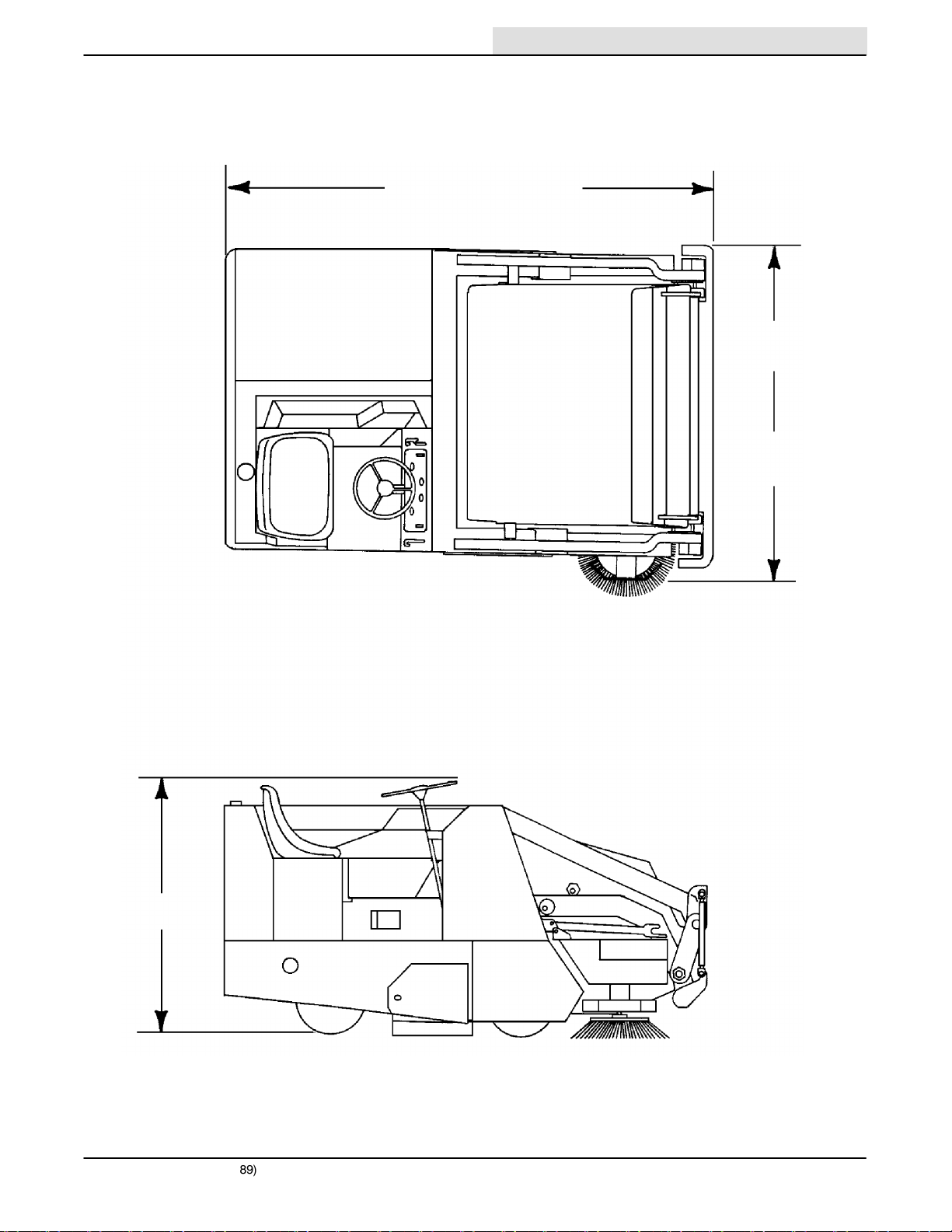
MACHINE DIMENSIONS
Home
Find...
Go To..
96 in (2440 mm)
Low Dump Model
98 in (2490 mm)
Multi-Level Dump Model
SPECIFICATIONS
56 in (1420 mm)
Low Dump Model
59 in (1500 mm)
Multi-Level Dump
Model
52 in (1320 mm)
275 SERIES II MM190 (12---89)
02452
1-5

SPECIFICATIONS
Home
Find...
Go To..
1-6
275 SERIES II MM190 (12---89)

CONTENTS
Home
Find...
Go To..
OPERATION
SECTION 2
OPERATION 2-1. . . . . . . . . . . . . . . . . . . . . . . . . . . . . . .
PREPARATION FOR OPERATION 2-3. . . . . . . . . . .
AFTER UNLOADING AND BEFORE
OPERATING THE MACHINE: 2-3. . . . . . . . .
OPERATION OF CONTROLS 2-4. . . . . . . . . . . . . . .
MACHINE COMPONENTS ---
MULTI-LEVEL DUMP MODEL SHOWN 2-4.
INSTRUMENT PANEL SYMBOLS 2-5. . . . . . . . .
CONTROLS AND INSTRUMENTS 2-7. . . . . . . .
BRAKE PEDAL 2-8. . . . . . . . . . . . . . . . . . . . . . . . .
DIRECTIONAL PEDAL 2-8. . . . . . . . . . . . . . . . . .
PARKING BRAKE LEVER 2-8. . . . . . . . . . . . . . . .
OPERATOR SEAT 2-8. . . . . . . . . . . . . . . . . . . . . .
SQUEEGEE SWITCH 2-8. . . . . . . . . . . . . . . . . . .
WATER VALVE SWITCH 2-8. . . . . . . . . . . . . . . . .
FUEL LEVEL GAUGE 2-8. . . . . . . . . . . . . . . . . . .
THROTTLE LEVER 2-8. . . . . . . . . . . . . . . . . . . . .
THROTTLE SWITCH 2-9. . . . . . . . . . . . . . . . . . . .
HAZARD LIGHT SWITCH 2-9. . . . . . . . . . . . . . . .
ENGINE CHOKE KNOB 2-9. . . . . . . . . . . . . . . . .
DRIVE LIGHTS SWITCH 2-9. . . . . . . . . . . . . . . . .
DIESEL PREHEAT PUSHBUTTON
AND INDICATOR 2-9. . . . . . . . . . . . . . . . . . . .
HOPPER DUMP LEVER 2-9. . . . . . . . . . . . . . . . .
HOPPER LIFT AND SIDE BRUSH LEVER 2-9. .
MAIN BRUSH POSITION LEVER 2-10. . . . . . . . .
MAIN BRUSH HEIGHT
ADJUSTMENT KNOB 2-10. . . . . . . . . . . . . . . .
STEERING WHEEL 2-10. . . . . . . . . . . . . . . . . . . . .
MAIN BRUSH, VACUUM FAN
AND FILTER SHAKER SWITCH 2-10. . . . . . . .
CLOGGED FILTER LAMP 2-10. . . . . . . . . . . . . . . .
ENGINE HOUR METER 2-10. . . . . . . . . . . . . . . . .
ENGINE COOLANT
TEMPERATURE GAUGE 2-11. . . . . . . . . . . . .
ENGINE OIL PRESSURE GAUGE 2-11. . . . . . . .
BATTERY CONDITION GAUGE 2-11. . . . . . . . . .
IGNITION SWITCH 2-11. . . . . . . . . . . . . . . . . . . . .
SIDE BRUSH POSITION LEVER 2-11. . . . . . . . . .
HOPPER SUPPORT BAR 2-11. . . . . . . . . . . . . . . .
TO ENGAGE HOPPER SUPPORT BAR 2-11.
TO DISENGAGE HOPPER
SUPPORT BAR 2-12. . . . . . . . . . . . . . . . . . .
SCRUB BRUSH POSITION LEVER 2-13. . . . . . .
SOLUTION FLOW KNOB 2-13. . . . . . . . . . . . . . . .
CIRCUIT BREAKERS 2-13. . . . . . . . . . . . . . . . . . .
Page
Page
MACHINE OPERATION 2-14. . . . . . . . . . . . . . . . . . . .
NORMAL SWEEPING OPERATION 2-14. . . . . . .
PRE-START CHECKLIST 2-14. . . . . . . . . . . . .
TO START MACHINE 2-14. . . . . . . . . . . . . . . .
TO SWEEP 2-15. . . . . . . . . . . . . . . . . . . . . . . . .
POST OPERATION CHECKLIST ---
ENGINE OPERATING 2-16. . . . . . . . . . . . .
TO STOP MACHINE 2-16. . . . . . . . . . . . . . . . .
POST OPERATION CHECKLIST ---
ENGINE STOPPED 2-16. . . . . . . . . . . . . . .
NORMAL SCRUBBING OPERATION 2-17. . . . . .
PRE-START CHECKLIST 2-17. . . . . . . . . . . . .
TO START MACHINE 2-17. . . . . . . . . . . . . . . .
TO SCRUB 2-18. . . . . . . . . . . . . . . . . . . . . . . . .
TO DRAIN RECOVERY TANK
AND EMPTY DEBRIS HOPPER 2-18. . . . .
POST OPERATION CHECKLIST ---
ENGINE OPERATING 2-19. . . . . . . . . . . . .
TO STOP MACHINE 2-19. . . . . . . . . . . . . . . . .
POST OPERATION CHECKLIST ---
ENGINE STOPPED 2-19. . . . . . . . . . . . . . .
DOUBLE SCRUBBING OPERATION 2-20. . . . . .
OPERATION ON GRADES 2-20. . . . . . . . . . . . . . .
VACUUM WAND 2-20. . . . . . . . . . . . . . . . . . . . . . .
TO OPERATE VACUUM WAND 2-20. . . . . . . .
HOPPER DOLLY 2-21. . . . . . . . . . . . . . . . . . . . . . .
TO REMOVE HOPPER WITH DOLLY 2-21. . .
TO INSTALL HOPPER WITH DOLLY 2-22. . . .
SCRUB ATTACHMENT 2-23. . . . . . . . . . . . . . . . . .
TO MOUNT SCRUB ATTACHMENT 2-23. . . .
TO REMOVE SCRUB ATTACHMENT 2-26. . .
SNOW BLADE 2-27. . . . . . . . . . . . . . . . . . . . . . . . .
TO INSTALL SNOW BLADE 2-27. . . . . . . . . . .
TO OPERATE SNOW BLADE 2-28. . . . . . . . .
TO REMOVE SNOW BLADE 2-29. . . . . . . . . .
SNOW BROOM 2-30. . . . . . . . . . . . . . . . . . . . . . . .
TO INSTALL SNOW BROOM
ASSEMBLY 2-30. . . . . . . . . . . . . . . . . . . . . .
TO OPERATE SNOW BROOM 2-32. . . . . . . .
MACHINE TROUBLESHOOTING ---
SWEEPING 2-34. . . . . . . . . . . . . . . . . . . . . . . . .
MACHINE TROUBLESHOOTING ---
SCRUBBING 2-35. . . . . . . . . . . . . . . . . . . . . . . .
TRANSPORTING MACHINE 2-36. . . . . . . . . . . . . . . .
PUSHING OR TOWING MACHINE 2-36. . . . . . . .
MACHINE JACKING 2-36. . . . . . . . . . . . . . . . . . . .
TO JACK UP MACHINE 2-36. . . . . . . . . . . . . .
MACHINE TIE-DOWNS 2-37. . . . . . . . . . . . . . . . . .
MACHINE STORAGE 2-38. . . . . . . . . . . . . . . . . . . . . .
STORING MACHINE 2-38. . . . . . . . . . . . . . . . . . . .
275 SERIES II MM190 (12---89)
2-1

OPERATION
Home
Find...
Go To..
2-2
275 SERIES II MM190 (12---89)
PREPARATION FOR OPERATION
Home
Find...
Go To..
AFTER UNLOADING AND BEFORE OPERATING
THE MACHINE:
1. Check the machine for shipping damage.
2. Read this manual carefully before operating or
servicing the machine.
FOR SAFETY: Do not operate the machine unless
operation manual is read and understood.
3. Check the hydraulic fluid level in the hydraulic
fluid reservoir, using the dipstick provided.
TENNANTr hydraulic fluid is recommended. If
TENNANTr hydraulic fluid is not available, use
only new, approved hydraulic fluid. See
Hydraulics in the Maintenance section.
4. Check the engine oil level.
5. Check the radiator coolant level.
OPERATION
WARNING: Hot engine coolant. Scalding
can result. Do not open radiator cap or
service cooling system until radiator and engine
is cool to the touch.
6. Check the main brush adjustment, as
described in Brushes in the Maintenance
section.
7. Check the air pressure of the rear tire.
8. Fill the fuel tank, or install an LPG fuel tank on
the machine.
WARNING: Machine can have static
electricity charge. When pouring fuel, spark
can ignite fuel causing fire or explosion. Connect
wire attached to fuel can to machine to discharge
spark before pouring fuel.
275 SERIES II MM190 (12---89)
2-3
OPERATION
Home
Find...
Go To..
J
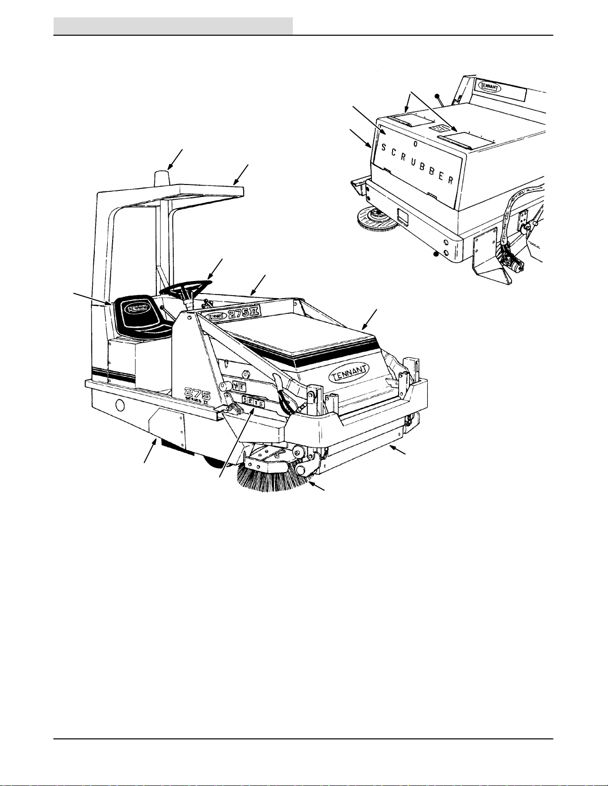
OPERATION OF CONTROLS
M
L
K
A
B
C
D
E
2-4
I
F
H
G
MACHINE COMPONENTS -- MULTI-LEVEL DUMP MODEL SHOWN
A. Hazard Light H. Hopper Support Bar
B. Overhead Guard I. Main Brush Access Door
C. Steering Wheel J. Operator Seat
D. Engine Cover K. Scrub Attachment
E. Hopper Cover L. Front Access Door
F. Hopper Door M. Solution Tank Covers
G. Side Brush
275 SERIES II MM190 (12---89)
02745
02746
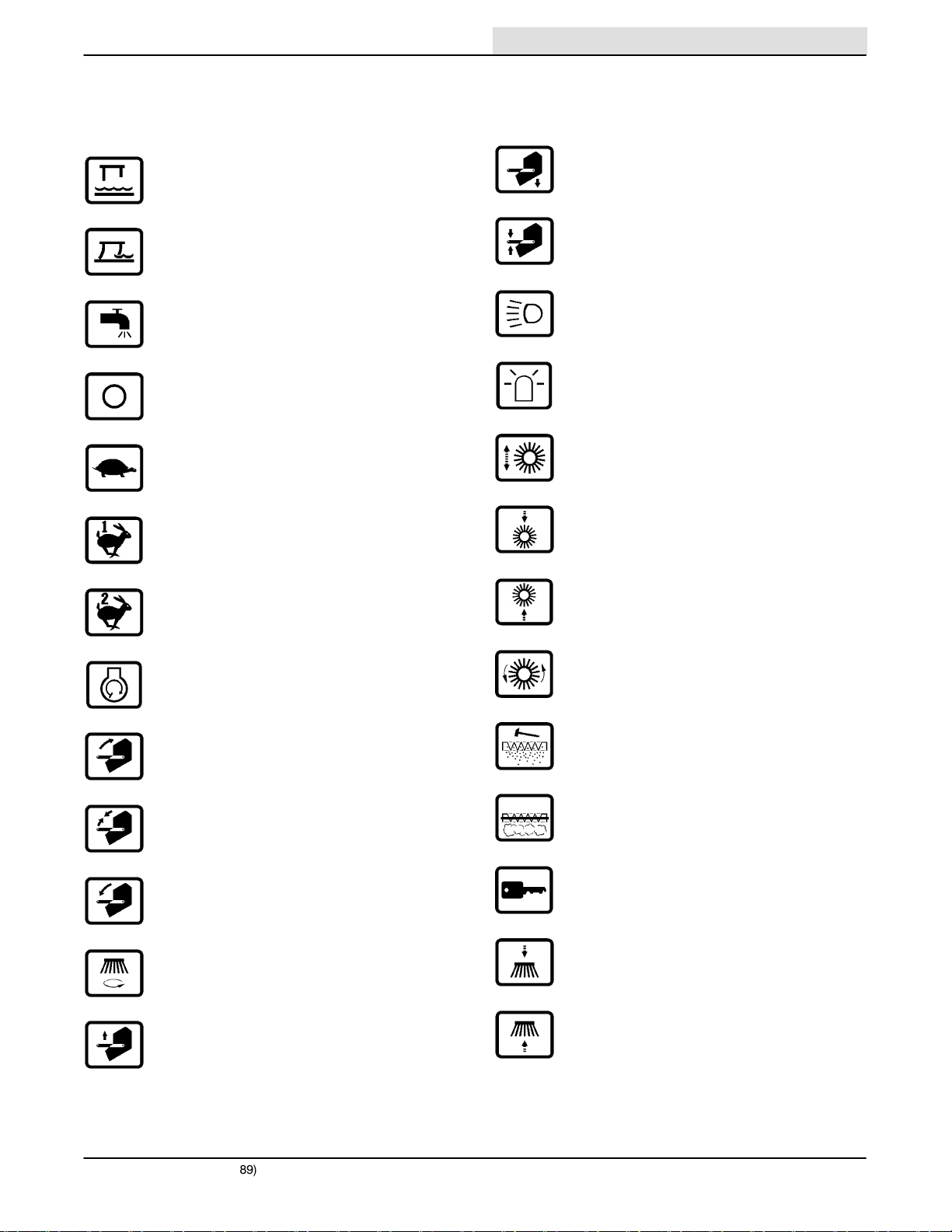
INSTRUMENT PANEL SYMBOLS
Home
Find...
Go To..
The symbols are used to identify controls and
displays on the machine:
OPERATION
Squeegee Up
Squeegee Down
Solution Flow
Diesel Off
Idle
Fast 1
Fast 2
Hopper Down
Hopper Hold
Headlights
Hazard Light
Main Brush Free-Float
Main Brush Down
Main Brush Up
Engine Start
Hopper Roll Out
Hopper Roll In/Out Hold
Hopper Roll In
Side Brush On
Hopper Up
Main Brush On
Filter Shaker
Filter Clogged
Key Switch
Side Brush Down
Side Brush Up
275 SERIES II MM190 (12---89)
2-5
OPERATION
Home
Find...
Go To..
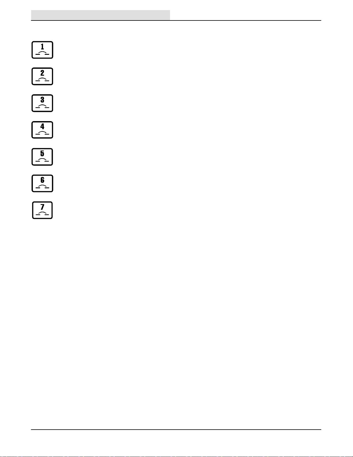
INSTRUMENT PANEL SYMBOLS (cont.)
Circuit Breaker 1
Circuit Breaker 2
Circuit Breaker 3
Circuit Breaker 4
Circuit Breaker 5
Circuit Breaker 6
Circuit Breaker 7
2-6
275 SERIES II MM190 (12---89)
OPERATION
Home
Find...
Go To..
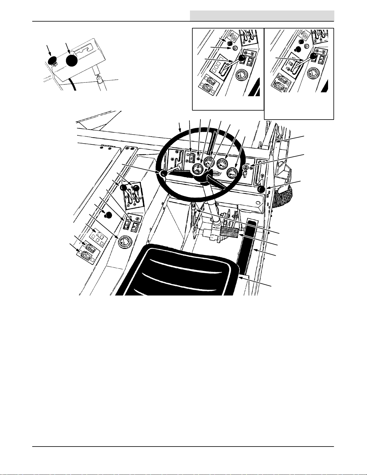
CC
BB
DD
M
L
H
Diesel Powered
Machines
ST
R
Q
U
V
W
X
H
(Gasoline and LPG
powered machines
below serial number
006500)
AA
Y
P
O
N
Z
K
I
J
G
F
E
A. Brake Pedal Q. Steering Wheel
B. Directional Pedal R. Main Brush, Vacuum Fan And
C. Parking Brake Lever Shaker Switch
D. Operator Seat S. Clogged Filter Lamp
E. Squeegee Switch T. Engine Hour Meter
F. Water Valve Switch U. Engine Coolant Temperature Gauge
G. Fuel Level Gauge V. Horn Button
H. Throttle Lever W. Engine Oil Pressure Gauge
I. Hazard Light Switch X. Battery Condition Gauge
J. Engine Choke Knob Y. Ignition Switch
K. Drive Lights Switch Z. Side Brush Position Lever
L. Diesel Preheat Indicator AA.Hopper Support Bar
M. Diesel Preheat Pushbutton BB.Scrub Brush Position Lever
N. Hopper Dump Lever CC.Solution Flow Knob
O. Hopper Lift and Side Brush Lever DD.Throttle Switch
P. Main Brush Position Lever
275 SERIES II MM190 (12---89)
CONTROLS AND INSTRUMENTS
C
A
B
D
05954
02747
05953
04637
2-7
OPERATION
Home
Find...
Go To..
BRAKE PEDAL
The brake pedal operates the mechanical drum
brakes on the two front wheels.
To stop the machine, return the directional pedal to
neutral; then apply pressure to the brake pedal.
DIRECTIONAL PEDAL
The directional pedal controls the propelling drive. It
is used to select the direction of travel and the
propelling speed of the machine.
A
B
C
SQUEEGEE SWITCH
The squeegee switch is present on machines
equipped with the rear squeegee or scrub
attachment accessories. The switch controls the
position of the rear squeegee.
To raise the rear squeegee, place the switch in the
top (Squeegee Up) position. To lower the rear
squeegee, place the switch in the bottom
(Squeegee Down) position.
WATER VALVE SWITCH
The water valve switch is present on machines
equipped with the scrub attachment accessory. The
switch controls solution flow to the floor. The solution
flow knob mounted on the scrub attachment controls
the solution flow rate to the floor.
To start the solution flow to the floor from the scrub
attachment tank, place the switch into the top
position. To stop the solution flow to the floor, place
the switch into the bottom position.
00116
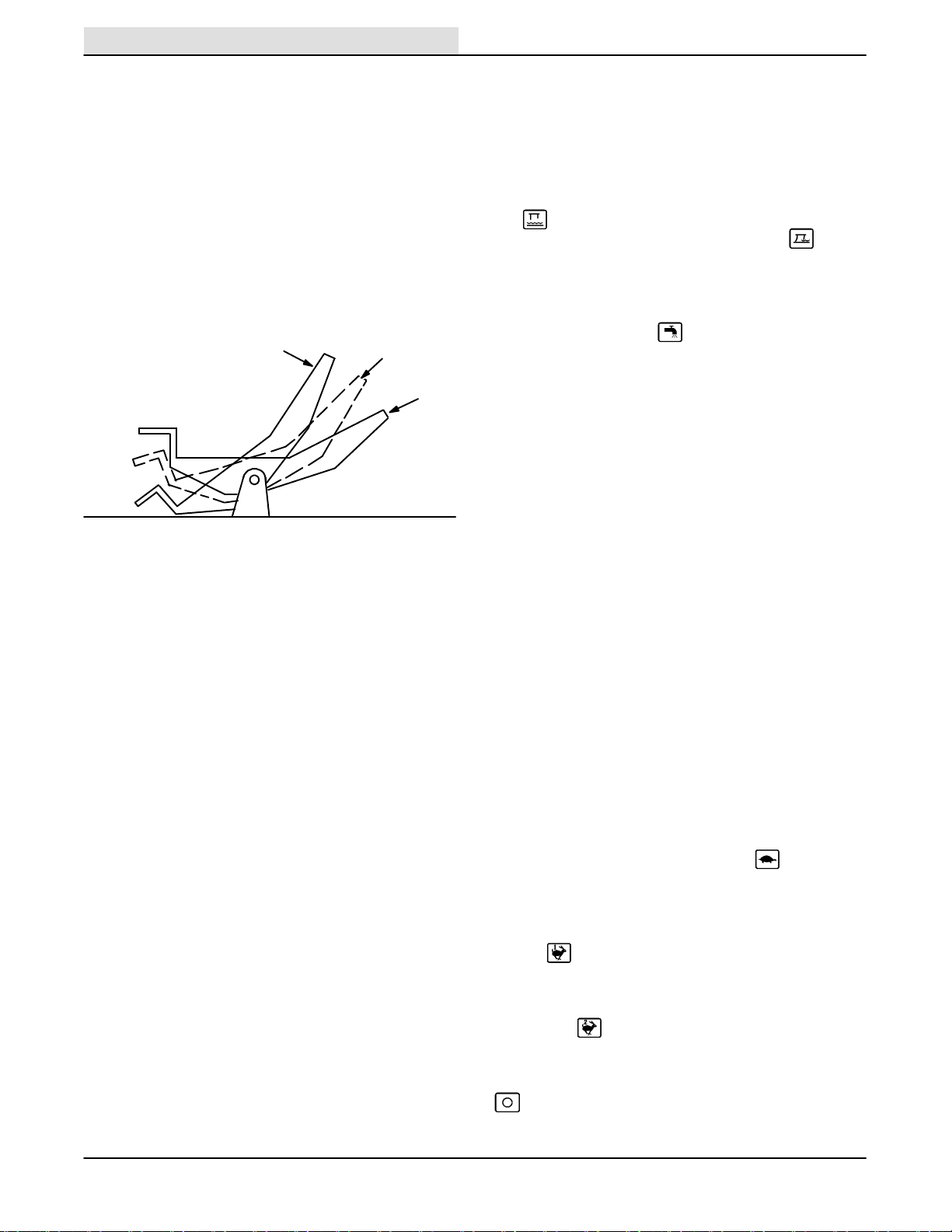
DIRECTIONAL PEDAL
A. “Reverse” Position
B. “Neutral” Position
C. “Forward” Position
To travel forward, press the “toe” portion of the
pedal; to travel backward, press the “heel” portion of
the pedal. The propelling speed of the machine is
regulated by varying the pressure on the pedal.
PARKING BRAKE LEVER
The parking brake lever operates the front wheel
brakes. To engage the parking brake, push the
parking brake handle down. To disengage the
parking brake, pull the brake handle up. Always park
on a level surface, stop the engine, and engage the
parking brake before leaving the machine
unattended and before working on the machine.
OPERATOR SEAT
The operator seat is of a fixed back style with a
forward-backward adjustment. To adjust the seat,
remove the seat mounting bolts, slide the seat to the
position desired, and reinstall and tighten the bolts.
The operator seat also tilts forward to allow access to
the fuel tank.
FUEL LEVEL GAUGE
The fuel level gauge is present on machines with the
fuel level gauge accessory. It indicates how much
fuel is left in the fuel tank. Machines without the
instrument panel mounted gauge have a mechanical
gauge built into the fuel tank cap.
THROTTLE LEVER
The throttle lever controls the engine governed
speed on gasoline and LPG powered machines
below serial number 006500. The throttle lever
controls the engine governed speed and stops the
engine on all diesel powered machines.
When starting the engine and to slow the engine
speed to idle, push the lever into the (Idle)
position.
To pick up normal debris, speed the engine to the
normal governed speed by pulling the lever into the
middle (Fast 1) position.
To pick up light litter, speed the engine to the
maximum governed speed by pulling the lever to the
left into the (Fast 2) position.
To stop the engine on a diesel powered machine,
pull the lever all the way to the right into the
(Diesel Off) position.
2-8
275 SERIES II MM190 (12---89)
 Loading...