

Page 1

6C
ASSEMBLY INSTRUCTIONS
ANTENNA MODEL T6
MI: 030927 (Secure this number someplace, for possible future need)
SPECIFICATIONS:
FORWARD GAIN 5.1 dBd
F:B RATIO 15-25 dB (Rises with frequency)
FREQUENCY COVERAGE 13-30 MHz
NOMINAL MAXIMUM SWR 2:1
FEED WITH 50-52 Ohm Coax Cable
POWER CAPABILITY Legal Limit+
ALUMINUM ALLOY 6061-T6
HARDWARE Stainless Steel
WEIGHT 29 Lbs
WIND AREA 6.2 SQ FT
WIND LOAD @ 80 MPH 100 Lbs
SUGGESTED MAST 2” OD Max.
LONGEST ELEMENT 38 ft
TURNING RADIUS 20 ft
MAXIMUM WIND 100 MPH
NUMBER OF ELEMENTS 6
© 2004 and beyond, TENNADYNE LLC. – All rights reserved.
TENNADYNE® LLC.
P.O. Box 352
Alto, MI 49302
Tel: 616.868.9907
E-mail: [email protected]
1
Page 2

6P
PARTS LIST ANTENNA MODEL: T6 MI: 030927
P/n DESCRIPTION QUAN
ALUMINUM TUBES:
01 1.500” square x 72” Boom Section 1 2
02 1.500” square x 72” Boom Section 2 2
03 1.000” round x 23.1” 2
04 .875” round x 36” 2
05 .875” round x 25.6” 2
06 .750” round x 24” 4
07 .625” round x 36” 4
08 .625” round x 34.3” 2
09 .625” round x 5.8” 2
10 .500” round x 48” 8
11 .500” round x 28.6” 2
12 .500” round x 9.9” 2
13 .375” round x 72” 12
14 Boom splice inserts – 8” 2
15 Mast insulator reinforcement washers (thick) 4
16 U-Bolts ss 2
17 Plastic boom-mast insulator 1
18 Large flat plastic spacers 2
19 Flat plastic spacers 4
P/n DESCRIPTION QUAN
20 BOLTS: 3/8-16 x 3.5” 4
21 ¼-20 x 2” (Element #1 only) 2
22 10-24 x 2.5” 8
23 10-24 x 1-1/2” 10
24 10-24 x 1-1/4” 10
25 10-24 x 1.0” 10
26 6-32 x ¾” 12
27 10-24 x ½” Hex (& wrench) 10
28 NUTS: ¼-20 Nylock ss 2
29 3/8-16 Nylok ss 8
30 10-24 Nylock 58
31 6-32 Nylok ss 12
32 WASHERS 8
33 U-Shaped shorting stub 1
34 Choke Plate with Tie Wrap 1
35 Instructions
T6 BOOM LAYOUT MI: 030927
FROM END
OF TUBE
BS# w/NUMBER HOLE SIZE FUNCTION
1 2.0” 1.000” Element #1
4.0” .1875” Large Flat Spacer
6.0” .1875” Large Flat Spacer
43.1” .875” Element #2
64.0” .375” Boom-Mast Insulator
67.0” .375” Boom-Mast Insulator
69.0” .1875” Splice
71.0” .1875” Splice
2 1.0” .1875” Splice
3.0” .1875” Splice
4.4” .625” Element #3
30.0” .1875” Flat Spacers
31.4” .625” Element #4
53.3” .500” Element #5
68.0” .1875 Flat Spacer
71.0” .500” Element #6
71.7” .1875” Coax Cable Attach
2
Page 3
ASSEMBLY INSTRUCTIONS ——— MODEL T6
This antenna has two booms, one will be placed atop the other and these booms are machined so that the elements pass directly through them. There are intentionally tight tolerances here, typically 1 or 2 thousandths of an inch, DO NOT FILE OUT THE HOLES MACHINED IN THE
BOOMS. Rather, if you must, use a fine emery cloth applied to the element itself.
You will need the usual assortment of small hand tools to assemble this antenna as well as quality black electrical
tape. We recommend the use of a mixture of WD-40 and lock graphite, or similar compound, to lubricate each and
every tubing joint and screw hole during assembly, the end of each element being placed into the boom and the boom
splices.
SALT AIR? You need to seal each tubing joint with minimal amounts of tape, heat-shrink, Etc. Use absolutely no more
of these materials than is needed, excess on the outside of the tubes can cause an unwanted shift in the velocity of
propagation along the tube. Completely cover the protruding stainless steel boom hardware with a sealant to avoid
corrosion and resultant galvanic action that can cause electrical noise.
GET ORGANIZED
Organize the tubing into groups, first by tube OD and then by length and check all against the parts list to make sure
it’s all there.
ASSEMBLY
The following steps are doubles, do each one twice and in exactly the same way. Place the BOOM SECTIONS (BS)
so that the BS 1, Etc., marked on the tube is facing up and, relatively, to your left. These will be done in sequence,
from BS 1 through BS 2. The distances noted in the INTO WHAT column are from the numbered end of the BS tube.
See FIGS. 1, 2 & 3. RIGHT & LEFT are relative, the object is to alternate directions.
CAUTION: Here is where you need to be precise and follow the directions implicitly.
STEP WHAT GOES INTO WHAT FASTEN WITH
***NOTE: Insert the end where there is an identifying mark machined above the hole. This
identifies that this end of the tube is to be inserted into the BS.
1 1.000” x 23.1” tube BS 1 to the RIGHT at 2.0” ¼-20 x 2” bolt & nut
Do not tighten down these ¼” nuts. You will need to remove them later.
All following hardware installations are to be installed tightly.
2 .875” x 13.6” tube BS 1 to the LEFT at 43.1” 10-24 x 1.5” bolt & nut
3 .625” x 34.3” tube BS 2 to the RIGHT at 4.4” 10-24 x 1.5” bolt & nut
4 .625” x 5.8” tube BS 2 to the LEFT at 31.4” 10-24 x 1.5” bolt & nut
5 .500” x 28.6” tube BS 2 to the RIGHT at 53.3” 10-24 x 1.5” bolt & nut
6 .500” x 9.9” tube BS 2 to the LEFT at 71.0” 10-24 x 1.5” bolt & nut (SEE BELOW)
RIGHT-LEFT-RIGHT-LEFT-RIGHT-LEFT FOR EACH BOOM! EXACTLY THE
SAME FOR BOTH BOOMS! The point is, they alternate in direction in each boom separately, and this
is, perhaps, the best way to get that across.
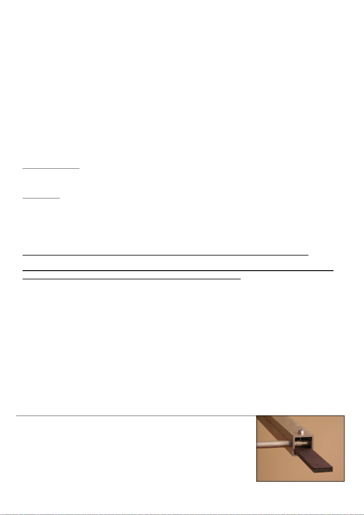
STEP 6: Before doing Step 6, get the Choke Plate which is a 6” length of flat PVC with
one hole drilled through it. Insert the end with the hole into Boom Section 2 and underneath where the .500” x 9.9” tube will be inserted. Then take the 10-24 x 1.5” bolt and
insert it through Boom Section 2 AND through the Choke Plate up through the .500”
tube and then out the other side of Boom Section 2. Tighten down with nut provided.
The picture to the right is provided to clarify the installation of the Choke Plate.
This is to be ONLY installed on ONE Boom Section 2. It doesn’t matter which.
3
Page 4
ASSEMBLE THE BOOM SECTIONS ONE-TO-ANOTHER – Retain the position of the BS with the numbers
marked thereon facing upward and, relatively, to your left. Again, do each of the following steps twice.
********** Proceed with steps 7 through 8 using supplied Allen Wrench. **********
STEP WHAT GOES -----------INTO WHAT--------- FASTEN WITH______________
7 Splice inserts BS 1 inside the right end 10-24 x ½” Socket HD Cap Screws & nuts
Position the ½” Socket HD Cap Screws on the tip of supplied Allen Wrench and insert it upward through the larger hole
(1/2” or 3/8”) in the bottom of the boom, continuing upward with it through the smaller hole in the top of the boom until the
Socket HD Cap Screw protrudes upward, and outside of the boom. Secure it here with the 10-24 nyloc nuts.
8 Join the BS1 to BS2 together at these splices 10-24 x ½” Socket HD Cap Screws & nuts
WIND NOISE: To lessen or prevent wind generated noise from the antenna, cover the holes in the boom with a good
quality black plastic electrical tape. Included are the holes through which you placed the element holding bolts, between
the booms. Looking down and into these holes, you will see the head of the element holding bolts.
You should now have a pair of identical 12 ft booms. Turn one of these booms upside down so that the numbers marked
thereon face downward.
THESE NEXT STEPS ARE SINGLES: Do them only to the boom with the numbers facing down. Install the spacers
so that they point up from this boom.
STEP WHAT GOES -----------INTO WHAT--------- FASTEN WITH_________
9 Large flat spacers BS 1 at A 10-24 x 2.5” machine screw & nut
10 Flat Spacers BS 2 at B 10-24 x 2.5” machine screw & nut
11 Flat spacers BS 2 at B 10-24 x 2.5” machine screw & nut
12 Pick up the other boom, the one with no spacers installed. Keep the numbers marked thereon facing upward and
install it atop the boom with spacers, sliding the top boom onto and between the spacers. Same machine screws
as above
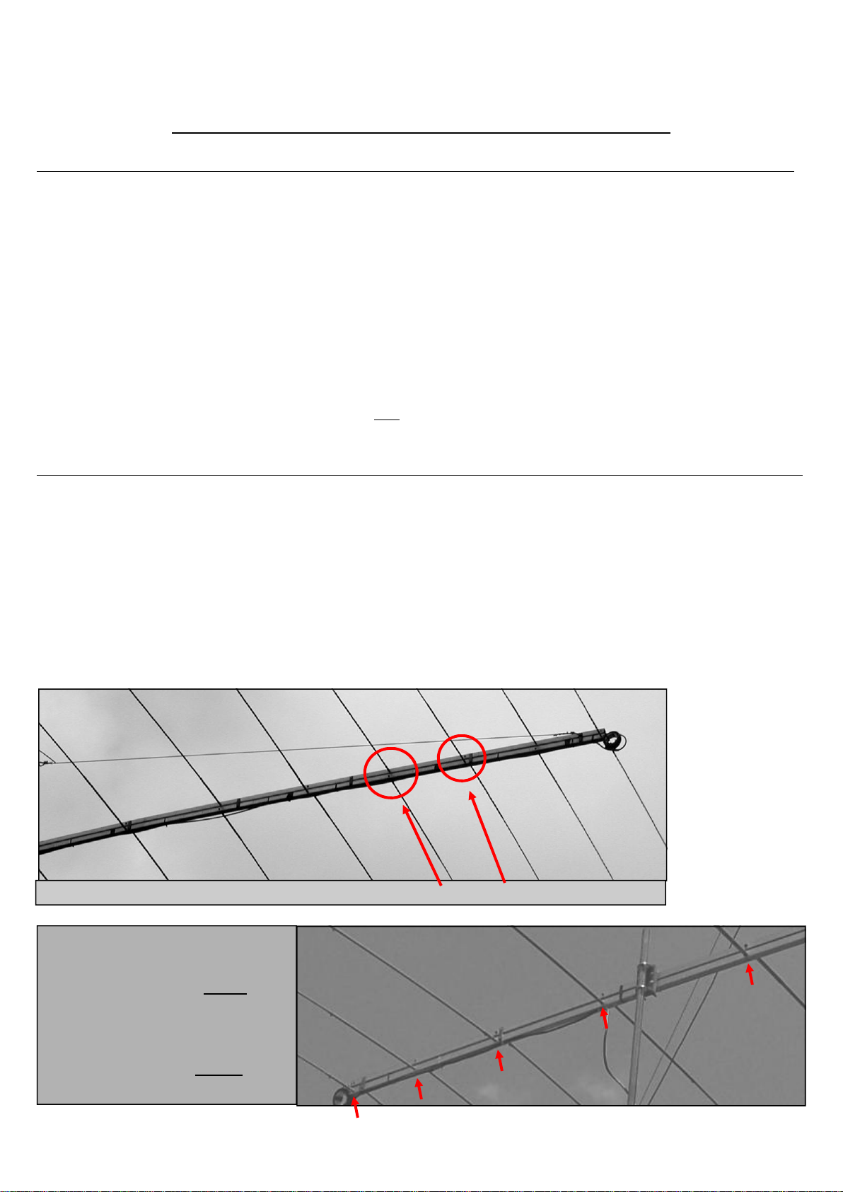
13 DO A RE-CHECK OF YOUR ASSEMBLY WORK: See FIG. 3. The elements in the top boom alternate,
first to one side and then to the other. Odd numbered elements go, say, right, and even numbered elements go
the opposite direction. The elements in the lower boom MUST, then, go in a direction opposite those in the upper
boom. You MUST understand this concept.
T12—all antennas are
assembled in this manner.
Notice how the elements alternate between the top and bottom booms.
This is an example of a WRONG install.
Look carefully and you will see ALL the
elements lined up on the bottom boom.
See the difference between the two
examples? The correct install is elements alternating—top/bottom/top/
bottom, etc. like the top picture.
Your SWR will be whacko if your
antenna looks like this!
T6
4
Page 5

THE ELEMENTS: Start with the smallest element, #6, at the front of the antenna. These are double steps, do each
twice, once for each side of the antenna. See FIG. 1
STEP WHAT GOES -----------INTO WHAT--------- FASTEN WiTH______
14 .375” x 72” tube .500” x 9.9” tube, Element # 6 6-32 x 3/4” machine screw & nut
15 .375” x 72” tube .500” x 28.6” tube, Element # 5 6-32 x 3/4” machine screw & nut
16 .375” x 72” tube .500” x 48” tube 6-32 x 3/4” machine screw & nut
17 Results of step 16 .625” x 5.8” tube, Element # 4 10-24 x 1.0” machine screw & nut
18 .375” x 72” tube .500” x 48” tube 6-32 x 3/4” machine screw & nut
19 Results of step 18 .625” x 34.3” tube, Element #3 10-24 x 1.0” machine screw & nut
20 .375” x 72” tube .500” x 48” tube 6-32 x 3/4” machine screw & nut
21 Results of step 20 .625” x 36” tube 10-24 x 1.0” machine screw & nut
22 Results of step 21 .750” x 24” tube 10-24 x 1-1/4” machine screw & nut
23 Results of step 22 .875” x 13.6” tube, Element # 2 10-24 x 1-1/4” machine screw & nut
24 .375” x 72’ tube .500” x 48” tube 6-32 x 3/4” machine screw & nut
25 Results of step 24 .625” x 36” tube 10-24 x 1.0” machine screw & nut
26 Results of step 25 .750” x 24” tube 10-24 x 1-1/4” machine screw & nut
27 Results of step 26 .875” x 36” tube 10-24 x 1-1/4” machine screw & nut
28 Results of step 27 1.000” x 23.1” tube, Element # 1 10-24 x 1-1/4” machine screw & nut
STOP AND COMPARE. DOES IT LOOK LIKE THE PHOTOS AND DRAWINGS IN THIS MANUAL?
29 Remove the nuts holding Element #1 in place, slip the shorting stub onto the bolts and re-apply the nuts, leav-
ing the shorting stub to protrude to the rear of the antenna. Reach into the element tube with long-nosed pliers
to hold the machine screws in place during this step.
The COLLINS BALUN (A common mode current choke)
Use 12 ft of only RG-8 or RG-213 coax cable for this. More is OK. The balun works best if the coil turns are
side-by-side as opposed to bunched. It also works as well as any available ferrite device. The coil is 3” or so
ID. Wind 4 turns side-by-side with another 4 turns wound directly atop the first 4.
The input and output thus end up on the same side. Alternatively, you can wind 8 side-by-side turns in one
layer, using the same coil ID.
Allow only 2-4 inches of cable between the balun and the antenna. One can often find plastic pipe fittings in a
hardware store to serve as a coil form.
30 Install the Boom-Mast Insulator at C on the booms.
Parts sequence is: Head of Bolt – Washer – BMI – Boom –
Mast Insulator Reinforcement Washers (thick washers) – Nut 3/8-16 x 3.5” bolts, Etc.
CAUTION – CAUTION – CAUTION
Make sure that the threads of these bolts are very clean and well lubricated.
31 Install the Collins Balun (CHOKE) at the front of the Antenna, at the smallest element, in front of the antenna
and onto the already installed Choke Plate using the supplied Tie Wrap. Wrap the Tie Wrap over and through
the inside of the CHOKE and then down and around the Choke Plate. Tighten the Tie Wrap firmly. Now install
the Choke to the Boom Sections. Take the Center Conductor and install it on the top boom. Take the Braid and
install it on the bottom boom. Secure both the Center Conductor and Braid to the Boom Sections using the sup-
plied 10-24 x ½” machine screws & nuts.
THE COAX CABLE BACK TO THE CENTER OF THE ANTENNA, AND THE MAST,
IS ATTACHED TO AND DIRECTLY BENEATH THE LOWER BOOM.
32 See FIG. 5 Mount the antenna to your mast at the BMI using 3/8-16 U-Bolts, washers & nuts
CAUTION – CAUTION – CAUTION
Make sure that the threads of these U-Bolts are very clean and well lubricated.
TENNADYNE
616.868.9907
[email protected]
5
Page 6

FIG. 1
TUBE SIZES AND LENGTHS USED TO MAKE THE ELEMENTS
PLEASE NOTE: The actual lengths of most tubes will be a bit shorter than the lengths
in the below table.
TUBE SIZES
ELEMENT 1.000”.875” .750” .625” .500” .375”
1 23.1” 36” 24” 36” 48” 72”
2 25.6” 24” 36” 48” 72”
3 34.3” 48” 72”
4 5.8” 48” 72”
5 28.6” 72”
6 9.9” 72”
FIG. 2
ELEMENT PLACEMENT v. BOOM SECTION
DISTANCE
FROM LEFT BOOM
ELEMENT END OF BOOM SECTION
1 2.0” 1
2 43.1”
3 4.4” 2
4 31.4”
5 53.3”
6 71.0”
FIG. 3
x This is what half, of the antenna should look
x like, only one of the two booms. The other
x x half should have elements pointing in the
x x opposite direction.
x x x
x x x SS = Shorting Stub
x x x FP = Feed Point
x x x
SS BoomBoomBoomBoomBoomBoom FP
x x x
x x x
x x x
x x x
x x
x x
x
x
6
Page 7
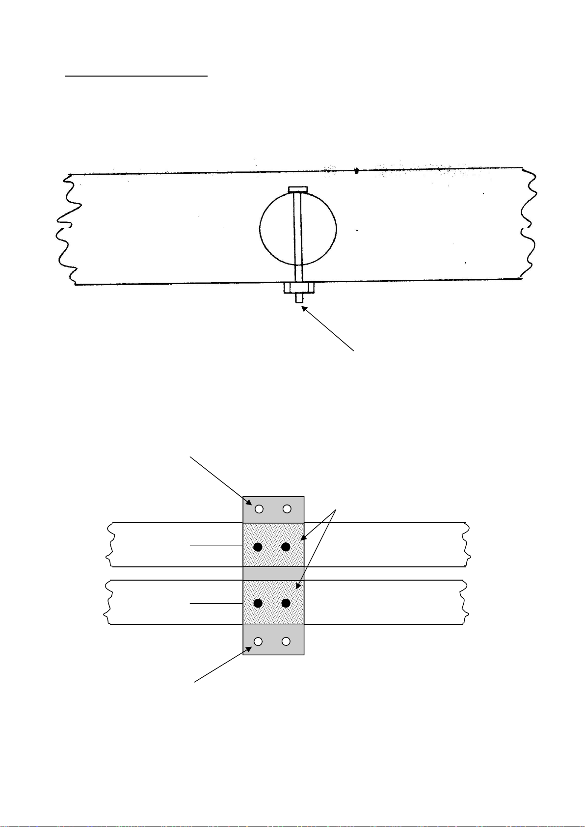
Elements to Boom Assembly
Refer back to Fig. 3, insert the larger end of the proper element into the proper hole in the boom
and secure the element into place with a 10-24 x 1 12” through the 3/8” hole, through the ele-
ment and out the smaller hole. Then, secure it with the nylok nut, don’t dent the boom too
much.
Fig. 4
These bolts extend away from the
other boom following final assembly.
——————————————————————————————————————————————————————————
Fig. 5
BMI—holes for U-bolt
Reinforcement Washers
Bolts here
Bolts here
Upper Boom
Lower Boom
BMI—holes for U-bolt
7
Page 8
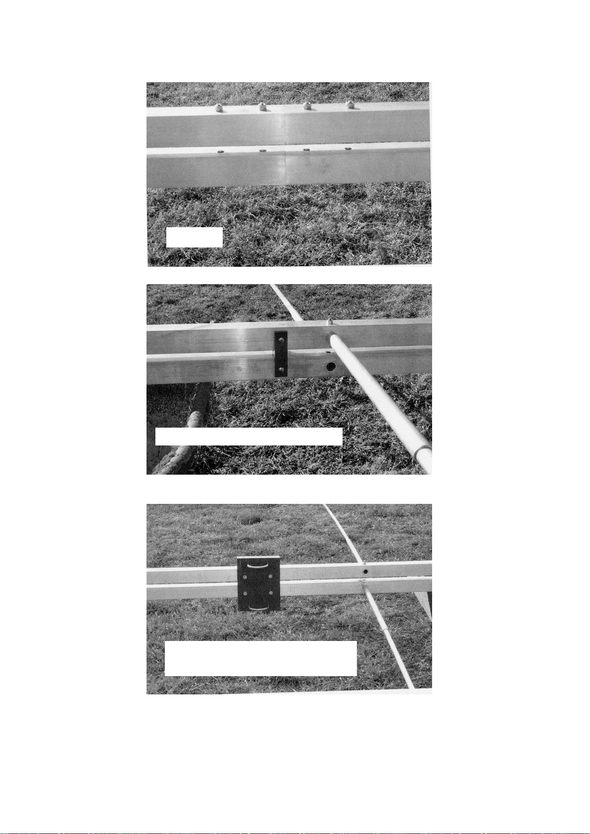
Insert
An element with flat spacers.
The Boom-to-Mast insulator and
an element.-U-bolt
8
 Loading...