

Page 1
TENNADYNE
®
Aluminum with a PhD
ASSEMBLY INSTRUCTIONS
MODEL: T10 - 100224
SPECIFICATIONS:
FREQUENCY COVERAGE 13-33 MHz
FORWARD GAIN 6.1 dBd
½ POWER BEAMWIDTH 52 DEGREES
F:B RATIO To 25 Db (Rises with frequency)
NOMINAL MAXIMUM SWR 1.7:1
FEED WITH 50-52 OHM COAXIAL CABLE
POWER CAPABILITY LEGAL LIMIT+
BOOM LENGTH 24 FT
WEIGHT 68 LBS
WIND AREA 10.1 SQ FT
WIND LOAD @ 80 MPH 162 LBS.
LONGEST ELEMENT 38 FT
TURNING RADIUS 22 FT
SUGGESTED MAST 2” OD
MAXIMUM WIND 100 MPH
ALUMINUM ALLOY 6061-T6 (Mill finish)
HARDWARE STAINLESS STEEL
NUMBER OF ELEMENTS 10
NOTE: The above performance characteristics are nominals and may vary from installation to installation.
© TENNADYNE LLC. 2010 and beyond – All rights reserved
Price: $4.95
Tennadyne
Log Periodic Antennas
P.O. Box 352; Alto, MI 49302; 616. 622.4968
WWW.TENNADYNE.COM
Page 2

SAFETY FIRST!
LOOK UP AND LIVE.
POWER LINE CONTACTS
CAN KILL!
LIMITED WARRANTY
TENNADYNE, LLC warrants on the terms hereof, to the original purchaser of this product, for a period of one year from the date of purchase, that the
product was not defective, but this warranty is void if the product has been subjected to improper or abnormal installation or usage.
If a customer believes that a product is defective, the customer may, within such one-year period, return the entire product to TENNADYNE at TENNADYNE’S factory, all shipping charges pre-paid by the customer. If the product was defective, TENNADYNE will at its option and expense repair or
replace the product and will at its expense return the repaired or replaced product to the customer, in a manner selected by TENNADYNE, at the address from which the customer sent the product to TENNADYNE.
The above warranty and remedy are exclusive and are in lieu of all other warranties, express or implied, including but not
limited to implied warranties of merchantability and fitness for a particular purpose.
No seller will be liable for any loss, inconvenience or damage, including direct, special, incidental or consequential damages resulting from
the use of or inability to use a product, whether the liability would result from breach of warranty or under any other legal theory.
This warranty does not cover damage to or caused by an antenna (a) by reason of the antenna acting as a lightning rod, (b) by reason of corrosion or
strain from exposure of an antenna to wind or weather, (c) from improper assembly, installation or use of an antenna, (d) from failure periodically to
inspect and maintain an antenna and its installation, or (e) the antenna coming into contact with a source of electrical power. The customer is responsible to insure that the installation and use of an antenna complies with applicable laws (such as zoning laws) and regulations (such as condominium
regulations).
The laws of some states do not allow the exclusion of implied warranties, and if these laws apply, then all express and implied warranties are limited in
duration to such one year period. No warranties of any kind apply after that period.
Such repair or replacement is the customer’s sole and exclusive remedy for a defective product. Specifically, TENNADYNE is not liable (to the customer or otherwise) for (a) any loss or damage arising in any way from a product or from actual or anticipated sale, lease, license or use of a product,
or involving in any matter such as interruption of service, loss or business or anticipated profits, or delay in receiving, repairing, replacing or returning a
product, or (b) any incidental, indirect, special or consequential damages.
No other person (such as an employee, agent or dealer) is authorized to change this warranty in any way, or to give any other warranties of any kind
on behalf of TENNADYNE. This warranty gives a customer specific legal rights, and a customer may also have other rights, which vary from state to
state.
As used herein, customer is the initial end-use purchaser of a product from seller, a product is an antenna therefore manufactured by TENNADYNE,
a product is defective if and only if the product was not free of defects of material and workmanship when manufactured, and a seller is TENNADYNE
and any authorized TENNADYNE dealer.
TENNADYNE, LLC
© 2010 and beyond – TENNADYNE, LLC
2
Page 3

T10 PARTS LIST
PART # DESCRIPTION QUAN
Aluminum Tube
01 Square 1.500” x 72” MARKED 1 2
02 1.500” x 72” MARKED 2 2
03 1.500” x 72” MARKED 3 2
04 1.500” x 72” MARKED 4 2
05 Round 1.000” x 23.1” 2
06 .875” x 36” 2
07 .875” x 33.8” 2
08 .875” x 12.8” 2
09 .750” x 24” 6
10 .750” x 16.0” 2
11 .625” x 36” 8
12 .625” x 33.0” 2
13 .625” x 17.9” 2
14 .625” x 4.2” 2
15 .500” x 48” 14
16 .500” x 38.0” 2
17 .500” x 27.0” 2
18 .500” x 17.1” 2
19 .375” x 72” 20
20 BOOM SPLICE INSERTS – 8” 6
21 LARGE FLAT SPACERS 4
22 SMALL FLAT SPACERS 12
23 PLASTIC BOOM-MAST INSULATOR (BMI) 1
24 BMI REINFORCEMENT THICK WASHERS 4
25 SLIPPNOTT CLAM SHELLS (pair) 1
BOLTS & MACHINE SCREWS
26 B 3/8-16 x 3.5” Hex 4
27 3/8-16 x 4.5” for SLIPPNOTTS 4
28 MS ¼-20 x 2” (Element # 1) 2
29 MS 10-24 x 2.5” 20
30 MS 10-24 x 1.5” 18
31 MS 10-24 x 1-1/4” (Elements) 16
32 MS 10-24 x 1.0” (Elements) 14
33 MS 6-32 x ¾” (Element Tips) 20
34 MS 10-24 x ½” 2
35 MS 10-24 x ½” Cap Screws (w/wrench) 24
36 NUTS: ¼-20 Nylok 2
37 3/8-16 Nylok 8
38 10-24 Nylok 94
6-32 Nylok 20
39 WASHERS 16
40 U-SHAPED SHORTING STUB 1
41 INSTRUCTIONS 1
42 CHOKE PLATE & TIE WRAP 1
3
Page 4

T10 BOOM LAYOUT
FROM END
OF TUBE
BS# w/NUMBER HOLE SIZE FUNCTION Eventually will be:
1 2.0” 1.000” First Tube of Element # 1 6 nested tubes
4.0” .1875” Large flat spacer
6.0” .1875” Large flat spacer
40.0” .1875” Small Flat Spacer
48.9” .875” First Tube of Element # 2 5 nested tubes
69.0” .1875” Boom Splice
71.0” .1875” Boom Splice
- - - - - - - - - - - - - - - - - - - - - - - - - - - - - - - - - - - - - - - - - - - - - - - - - - - - - - - - - - - - - - - - - - - - - 2 1.0” .1875” Boom Splice
3.0” .1875” Boom Splice
5.0” .1875 Large flat spacer
7.0” .1875” Large flat spacer
19.0” .875” First Tube of Element # 3 5 nested tubes
41.0” .1875” Small Flat Spacer
56.8” .750” First Tube of Element # 4 4 nested tubes
64.5” .375” Mast Insulator
67.5” .375” Mast Insulator
69.0” .1875” Boom Splice
71.0” .1875” Boom Splice
- - - - - - - - - - - - - - - - - - - - - - - - - - - - - - - - - - - - - - - - - - - - - - - - - - - - - - - - - - - - - - - - - - - - - 3 1.0” .1875” Boom Splice
3.0” .1875” Boom Splice
18.7” .625” First Tube of Element # 5 3 nested tubes
32.0” .1875” Small Flat Spacer
49.2” .625” First Tube of Element # 6 3 nested tubes
67.0” .1875 Small Flat Spacer
69.0” .1875” Boom Splice
71.0” .1875” Boom Splice
- - - - - - - - - - - - - - - - - - - - - - - - - - - - - - - - - - - - - - - - - - - - - - - - - - - - - - - - - - - - - - - - - - - - - 4 1.0” .1875” Boom Splice
3.0” .1875” Boom Splice
4.5” .625” First Tube of Element # 7 3 nested tubes
29.1” .500” First Tube of Element # 8 2 nested tubes
31.0” .1875” Small Flat Spacer
51.2” .500” First Tube of Element # 9 2 nested tubes
67.5” .1875 Small Flat Spacer
71.0” .500” First Tube of Element # 10 2 nested tubes
71.6” _____? Coaxial Cable Connection
4
Page 5

BEFORE ASSEMBLY
GETTING STARTED BY GETTING ORGANIZED - Organize the tubing into groups, first by tube OD (Outside Diame-
ter) and then by length and check all against the parts list to make sure it’s all there. Notify us immediately if you are
missing anything.
Tools - You will need the usual assortment of small hand tools to assemble this antenna as well as quality black electrical tape. We recommend the use of a mixture of WD-40 and lock graphite, or similar compound, to lubricate each and
every tubing joint and screw hole during assembly, the end of each element being placed into the boom and the boom
splice couplers.
Read - Read these instructions several times before starting the actual assembly process & until the process becomes
clear. Refer to FIGS. 1, 2 & 3 as you read to develop the understanding of how the antenna is constructed.
Left and Right - Left and Right, as used in these instruction, are arbitrarily assigned.. Assembled in the mirror image,
the result is just as good. BUT, following the directions as stated will keep you organized and once started MUST be
followed.
Assembly Phases - The antenna will be assembled in 5 phases:
Phase Description After which you will have
1 Boom Section Preparation 10 prepared Boom Sections 6 feet long (5 identical pairs)
with the first tube of the elements attached.
2 Boom Section Splicing After which you will have 2 identical sub-booms 24 feet long
3 Boom Completion Spacers attached and booms secured atop each other
4 Element Build Out Completed antenna with elements attached
5 Attachments and Feedline Installation of BMI, shorting stub, balun,
antenna ready to go in the air
ASSEMBLY INSTRUCTIONS
This antenna has two sub-booms, one will be placed atop the other to form one structural boom with two separate electrical paths. These sub-booms are machined so that the elements pass directly through them. There are intentionally
tight tolerances here, typically 1 or 2 thousandths of an inch, DO NOT FILE OUT THE HOLES MACHINED IN THE BOOMS.
Rather, if you must, use a fine emery cloth applied to the element itself.
Lubrication and Protection - Repeating here: We recommend the use of a mixture of WD-40 and lock graphite, or similar
compound such as Penetrox A, to lubricate each and every tubing joint and screw hole during assembly, the end of
each element being placed into the boom and the boom splices.
SALT AIR ENVIRONMENT? You need to seal each tubing joint with minimal amounts of tape, heat-shrink or similar seal-
ant. Note: Use absolutely no more of these materials than is needed. Excess on the outside of the tubes can cause an
unwanted shift in the velocity of propagation along the tube. Completely cover the protruding stainless steel boom hardware with a sealant to avoid corrosion and resultant galvanic action that can cause electrical noise.
5
Page 6
ASSEMBLY PHASE 1 - Boom Section Preparation (Steps 1—10)
The following steps are doubles.. Do each one twice - and in exactly the same way. Place the BOOM SECTIONS (BS?)
so that the BS 1, 2 or 3 marker label marked on the tube is facing up and to your LEFT. These will be done in sequence,
from the BS 1s through BS 3s, two pair at a time. The distances noted in the INTO WHAT column are from the end of the
BS tube marked with marker label BS?. Now, with the Boom Section (BS) running across in front of you, the RIGHT &
LEFT used in the INTO WHAT column are as viewed looking down the BS from the LEFT end of the BS. The object is
to alternate the sides of the BS that the elements protrude from.
Caution: Here is where you need to be precise and follow the directions exactly.
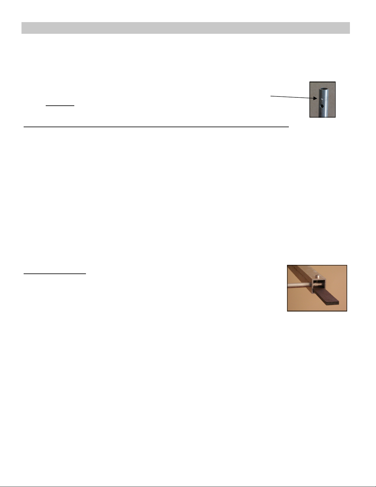
Also Note: Always insert the end of a tube where there is an identifying mark
machined above the hole. This machined mark must go into the Boom Section (BS)
STEP WHAT GOES INTO WHAT FASTEN WITH
1 1.000” x 23.1” tube BS 1 to the RIGHT at 2.0” ¼-20 x 2” machine screws & nuts
Do not run these ¼” nuts down tight, you will need to remove them later. See FIG. 4 for correct
Machine screw installation. All following hardware installation is to be installed tightly.
2 .875” x 33.8” tube BS 1 to the LEFT at 48.9” 10-24 x 1.5” machine screws & nuts
3 .875” x 12.8” tube BS 2 to the RIGHT at 19.0” 10-24 x 1.5” machine screws & nuts
4 .750” x 16.0” tube BS 2 to the LEFT at 56.8” 10-24 x 1.5” machine screws & nuts
5 .625” x 33.0” tube BS 3 to the RIGHT at 18.7” 10-24 x 1.5” machine screws & nuts
6 .625” x 17.9” tube BS 3 to the LEFT at 49.2” 10-24 x 1.5” machine screws & nuts
7 .625” x 4.2” tube BS 4 to the RIGHT at 4.5” 10-24 x 1.5” machine screws & nuts
8 .500” x 38.0” tube BS 4 to the LEFT at 29.1” 10-24 x 1.5” machine screws & nuts
9 .500” x 27.0” tube BS 4 to the RIGHT at 51.2” 10-24 x 1.5” machine screws & nuts
10 .500” x 17.1” tube BS 4 to the LEFT at 71.0” 10-24 x 1.5” machine screws & nuts ## See Below
RIGHT-LEFT-RIGHT-LEFT-RIGHT-LEFT FOR EACH BOOM SECTION
AND RESULTING BOOM! EXACTLY THE SAME FOR BOTH BOOMS!
## BEFORE STEP 10: Get the Choke Plate which is a 6” length of flat PVC with one hole drilled
through it. Insert the end with the hole into Boom Section 4 and underneath where the .500” x
17.1” tube will be inserted. Then take the 10-24 x 1.5” bolt and insert it through Boom Section 4
AND through the Choke Plate up through the .500” tube and then out the other side of Boom
Section 4. Tighten down with nut provided. The picture to the right is provided to clarify the installation of the Choke Plate.
This is to be ONLY installed on ONE Boom Section 4. It doesn’t matter which.
6
Page 7
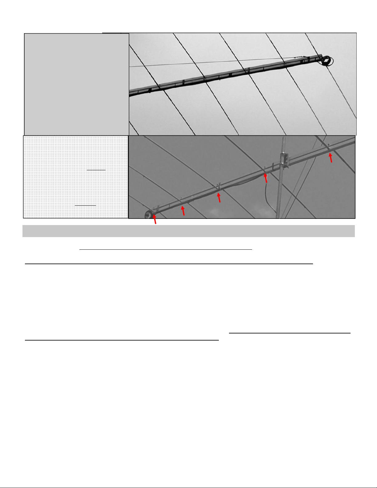
Element Placement on the Booms
T12 Shown - All antennas including
the T8 are assembled in this
manner.
Notice how the elements alternate
between the top and bottom booms.
T6 Shown - This is an example of
a WRONG install.
Look carefully - ALL the elements
are lined up on the bottom boom.
See the difference between the two
examples? The correct install has
elements alternating—top/bottom/
top/bottom, etc. like the top picture.
Your SWR will be whacko if your
antenna looks like this! ☺
T6
ASSEMBLY PHASE 2— Boom section splicing (Steps 11—14)
Position the BS with the number marked thereon to the left and with the number facing upward. Again, do each of
these steps twice. Proceed with steps 10 through 14 using supplied Allen Wrench.
STEP WHAT GOES INTO WHAT FASTEN WITH
11 8” splice insert BS 1 inside the right end 10-24 x ½” Socket HD Cap Screws & nuts
Position the ½” Socket HD Cap Screws on the tip of supplied Allen Wrench and insert it upward through
the larger hole (1/2” or 3/8”) in the bottom of the boom, continuing upward with it through the smaller
hole in the top of the boom until the Socket HD Cap Screw protrudes upward, and outside of the boom.
Secure it here with the 10-24 nyloc nuts.
12 8” splice insert BS 2 inside the right end 10-24 x ½” Socket HD Cap Screws & nuts
13 8” splice insert BS 3 inside the right end 10-24 x ½” Socket HD Cap Screws & nuts
14 Join the Boom Sections together at the splices, BS 1 to BS 2, Etc.10-24 x ½” Socket HD Cap Screws & nuts
You should now have two separate, but identical, 24 foot booms together. Turn one of these booms upside down so
that the numbers marked on its four Boom Sections all face down. Cover the boom holes with a good quality electrical tape at this time. Just the boom holes, the ones where you’ve inserted the machine screws that hold the elements
in place.
7
Page 8

ASSEMBLY PHASE 3—Boom completion (steps1 5—21)
These next steps are singles; do them ONLY to the boom you have just turned upside down. Install the spacers onto this
boom with the spacers pointing up.
STEP WHAT GOES INTO WHAT FASTEN WITH
15 Large flat spacer BS 1 at A near El #1 10-24 x 2.5” machine screws & nuts
16 Flat Spacers BS 1 at B 10-24 x 2.5” machine screw & nut
17 Large flat spacers BS 2 at A 10-24 x 2.5” machine screws & nuts
18 Flat Spacers BS 2 at B 10-24 x 2.5” machine screw & nut
19 Flat Spacers BS 3 at B Two places 10-24 x 2.5” machine screw & nut
20 Flat spacers BS 4 at B Two places 10-24 x 2.5” machine screw & nut
Place the remaining completed boom, numbers facing up, atop the boom with the spacers installed. Slide the top boom
down between the flat spacers using the same type fasteners as were used in Steps 1-20 above. (Flexing of the booms a
bit may be necessary here.) Nothing should be between these booms except air! The element halves should point in
opposite directions, i.e., half of #1 to the right with the other half of the same element to the left from the other
boom. The next element #2 halves must also alternate booms and be on the opposite boom sides as compared to ele-
ment #1.
Double Check - All other elements alternate booms and sides like elements #1 and #2. See FIG. 3. and photos. In other
words, as you go down the boom, the elements from the top boom must alternate RIGHT – LEFT – RIGHT – LEFT, Etc.
AND the lower boom elements must go in the opposite alternate directions.
Stop all assembly and check what you’ve done against FIG. 3.
This is where the most common assembly error occurs.
8
Page 9

ASSEMBLY PHASE 4—Element Build out (Steps 22– 33)
THE ELEMENTS: Start with the smallest element, #10, at the front of the antenna. These are double steps, do one step
for each side of the antenna. See FIG. 1.
STEP WHAT GOES INTO WHAT FASTEN WITH
On BS 4
22 .375” x 72” tube .500” x 17.1” tube: Element #10 6-32 x 3/4” machine screw & nut
23 .375” x 72” tube .500” x 27.0” tube: Element #9 6-32 x 3/4” machine screw & nut
24 .375” x 72” tube .500” x 38.0” tube: Element #8 6-32 x 3/4” machine screw & nut
25 .375” x 72” tube .500” x 48” tube 6-32 x 3/4” machine screw & nut
26 Results of Step 25 .625” x 4.2” tube: Element #7 10-24 x 1.0” machine screw & nut
On BS 3
27 .375” x 72” tube .500” x 48” tube 6-32 x 3/4” machine screw & nut
28 Results of Step 27 .625” x 17.9” tube: Element #6 10-24 x 1.0” machine screw & nut
29 .375” x 72” tube .500” x 48” tube 6-32 x 3/4” machine screw & nut
30 Results of Step 29 .625” x 33.0” tube: Element #5 10-24 x 1.0” machine screw & nut
On BS 2
31 .375” x 72” tube .500” x 48” tube 6-32 x 3/4” machine screw & nut
32 Results of Step 31 .625” x 36” tube 10-24 x 1.0” machine screw & nut
33 Results of Step 32 .750” x 16.0” tube: Element #4 10-24 x 1-1/4” machine screw & nut
34 .375” x 72” tube .500 x 48” tube 6-32 x 3/4” machine screw & nut
35 Results of Step 34 .625” x 36” tube 10-24 x 1.0” machine screw & nut
36 Results of Step 35 .750” x 24” tube 10-24 x 1-1/4” machine screw & nut
37 Results of Step 36 .875” x 12.8” tube: Element #3 10-24 x 1-1/4” machine screw & nut
On BS 1
38 .375” x 72” tube .500” x 48” tube 6-32 x 3/4” machine screw & nut
39 Results of Step 38 .625” x 36” tube 10-24 x 1.0” machine screw & nut
40 Results of Step 39 .750” x 24” tube 10-24 x 1-1/4” machine screw & nut
41 Results of Step 40 .875” x 33.8” tube: Element #2 i 10-24 x 1-1/4” machine screw & nut
42 .375” x 72” tube .500” x 48” tube 6-32 x 3/4” machine screw & nut
43 Results of Step 42 .625” x 36” tube 10-24 x 1.0” machine screw & nut
44 Results of Step 43 .750” x 24” tube 10-24 x 1-1/4” machine screw & nut
45 Results of Step 44 .875” x 36” tube 10-24 x 1-1/4” machine screw & nut
46 Results of Step 45 1.000” x 23.1” tube: Element #1 10-24 x 1-1/4” machine screw & nut
ASSEMBLY PHASE 5—Install shorting stub, BMI, & balun (Steps 47—49)
Before Proceeding - STOP AND COMPARE. DOES IT LOOK LIKE THE PHOTOS AND DRAWINGS ?
Step 47 - SHORTING STUB
Remove the nuts from the ¼-20 machine screws holding Element #1 in place, slip the shorting stub onto these and replace the nuts while positioning the stub per the photos. Reach into the element tube with long-nosed
pliers to hold the machine screws in place for tightening during this step.
The Collins Balun. This uses approximately 12 ft of ONLY RG-8 or RG-213 coaxial cable. For best results, the turns
are side-by-side, not bunched (See photo). Form a coil of 4 side-by-side turns of coax say, going from left to right. We
use a 3” light wall PVC pipe for a coil form. Secure (tape/tie-wrap) these first 4 turns in place and once you’ve done this,
go on top of the first 4 turns with another 4 turns, these will go from right to left. This causes both ends of the coil to be
on the same side. Allow only 2-5” of cable from the coil to the antenna feed point. If you construct your own, don’t use
so much tape that water cannot drain from the coil.
Step 48 - Install the Collins Balun (CHOKE) at the front of the Antenna, by the smallest element, in front of the antenna
and on the already installed Choke Plate using the supplied Hose Clamp. Wrap the Hose Clamp over and through the
inside of the CHOKE and then down and around the Choke Plate. Tighten the Hose Clamp firmly. Now electrically connect the Choke to the Boom Sections (feed points). Take the Center Conductor and install it on the top boom. Take the
Braid and install it on the bottom boom. Secure both the Center Conductor and Braid to the Boom Sections using the
supplied 10-24 x ½” machine screws & nuts. See Figure 7.
Step 49 - Mount the Boom-Mast Insulator on the booms, at the point labeled C, using 3/8” bolts, washers and nuts and
reinforcement Washers (thick washers). See FIG. 5 & 6. The parts sequence is: Head of bolt - washer – Boom-MastInsulator – Booms – Reinforcement Washers (thick washers) – Nuts 3/8-16 x 3.5” Bolts, Etc.
Step 50 - Mount the antenna to your mast. See FIG. 8. See CAUTION above.
SLIPP-NOTT Clamps (two half shells), 3/8-16 bolts, nuts & washers. Note: If your mast is of such a size that you need a
longer bolt for your SLIPP-NOTT Clamps, please give us a call and we will send them to you. The parts sequence is:
Head of bolt – Washer- Slipp-Nott Clamp (half shell) – Mast- BMI – Washer – Nuts (review picture).
CAUTION – In the following steps, make sure that the threads are clean and well lubricated.
9
Page 10

FIG. 1 TUBING SIZES AND LENGTHS USED TO MAKE UP THE ELEMENTS
Please note: The length tubes without decimals is approximate.
EL # / TUBE SIZE 1.000” .875” .750” .625” .500” .375” # nested tubes
1 23.1” 36” 24” 36” 48” 72” 6
2 33.8” 24” 36” 48” 72” 5
3 12.8” 24” 36” 48” 72” 5
4 16.0” 36” 48” 72” 4
5 33.0” 48” 72” 3
6 17.9” 48” 72” 3
7 4.2” 48” 72” 3
8 38.0” 72” 2
9 27.0” 72” 2
10 17.1” 72” 2
FIG. 2 ELEMENT PLACEMENT v. BOOM SECTION
DISTANCE
FROM LEFT
& MARKED BOOM
ELEMENT # END OF BOOM SECTION
1 2.0” 1
2 48.9”
3 19.0” 2
4 56.8”
5 18.7” 3
6 49.2”
7 4.5” 4
8 29.1”
9 51.2”
10 17.0”
______________________________________________________________________________________
FIG. 3 This is what HALF of the antenna should look like, a single boom only, when viewed from above
or below. The point is, the elements in the top boom alternate in direction, right-left-right-left, Etc.
The elements in the lower boom also alternate in direction but point opposite those in the top boom.
X
X
X x
X x
X x x
X x x
X x x x
X x x x
X x x x x
X x x x x
STUB BOOM BOOM BOOM BOOM BOOM BOOM BOOM FEED
X x x x x
X x x x x
X x x x
X x x x
X x x
X x x
X x
X x
X
X
UNDERSTAND THIS CONFIGURATION!
10
Page 11
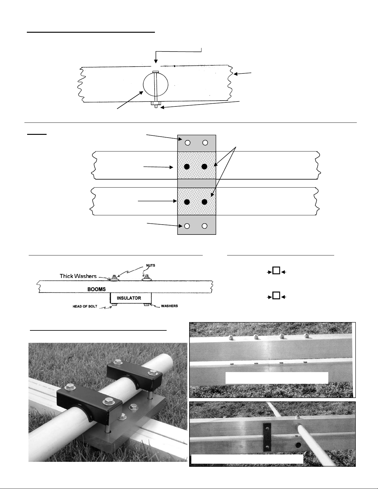
Fig. 4 - Elements to Boom Assembly
Referring to Fig. 1-3, insert the dimpled end of the proper element into the proper hole in the boom and secure the element into place with a 10-24 bolt through the 3/8” hole, through the element and out the smaller hole. Then, secure it
with the nyloc nut.
Element
Fig. 5 BMI—holes for U-bolt
or SlippNott
Bolts here
Bolts here
BMI—holes for U-bolt
or SlippNott
Boom
These bolts extend away from the other
boom following final assembly.
Reinforcement Washers
Upper Boom
Lower Boom
Fig. 6 - BOOM-MAST INSULATOR ATTACHMENT TO BOOM
Fig. 8 - ANTENNA TO MAST WITH SLIPP NOTT
Fig. 7 - COAX CABLE ATTACHMENT
Top Boom Center conductor
to either side
Lower Boom Shield to either
side
BS Splices with Coupler Inserted
Boom with Flat Spacers Shown
11
Page 12
12
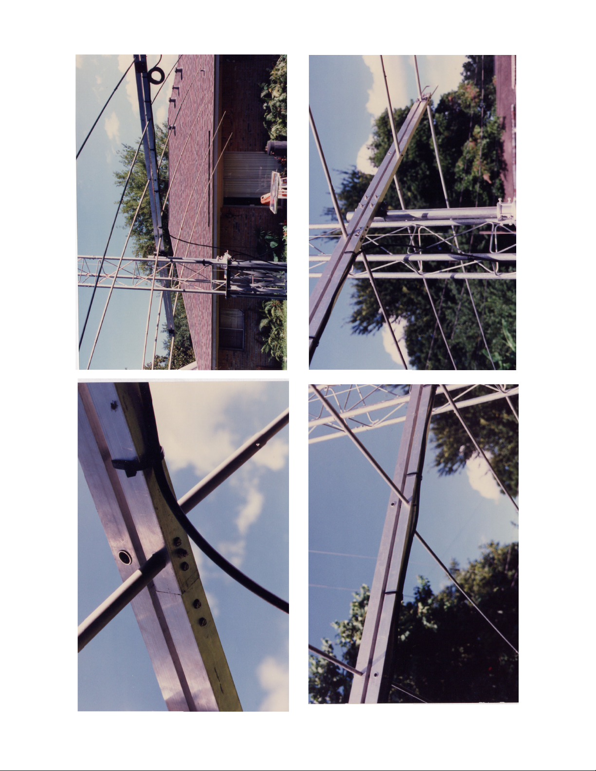
These photos show proper element phase reversal and attachment of the coax to the lower boom.
 Loading...