

Page 1
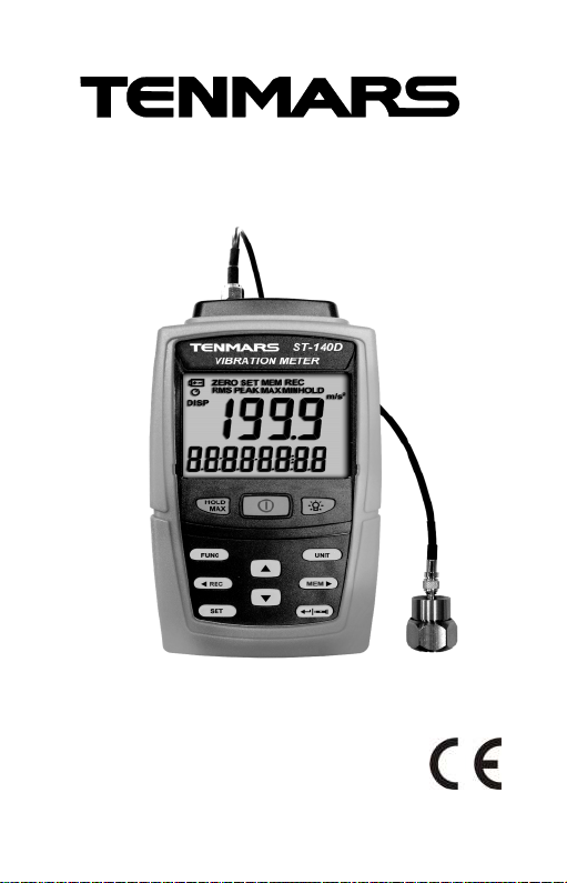
ST-140 Vibration Meter
ST-140D Datalogging Vibration Meter
User’s Manual
HB2ST1400001
Page 2

CONTENTS
1 Introduction.......................................................1
2 Accessories.......................................................1
3 Safety Precaution..............................................1
4 Meter Description..............................................2
5 Operation..........................................................3
5.1 Turn ON backlight 4
5.2 Datalogging Single Sata Entry Manually: 4
5.3 Reading Record Data In Memory: 4
5.4 Data Hold And Maximum Read Value: 4
5.5 Auto Power Off: 4
5.6 Accelerometer Installation: 5
5.7 Function Settings: Step 1~Step 6 7
6 Software Installation........................................10
7 General Specifications ....................................11
8 Electrical Specifications:..................................12
9 Maintenance or Repair....................................13
10 Battery Replacement.......................................13
11 End of Life Disposal ........................................13
Page 3
ST-140/ST-
140D
1
1 Introduction
This meter measures the vibrations of the rotating and
reciprocating machines, as well as bearing damage,
measurement items are acceleration, speed, displacement,
which can check if the machine is to be repaired or
upgrade.
2 Accessories
1 Meter
1 User manual
1 Accelerometer
1 Low noise cable
1 Magnetic base
6 1.5V UM4/AAA battery
11Carrying case
9V AC to DC adaptor
1 USB cable and Installation disk (ST-140D)
1 Handheld probe + round probe + pointed probe
3 Safety Precaution
Do not operate in environments with flammable gas or
humid environments.
Operating altitude: up to 2000M.
Operating environment: Indoor use; Pollution degree 2.
Clean with soft cloth when dirty, such as glasses cloth.
Do not clean with chemicals and other solvents.
EMC: EN61326-1:CISPR 11:Group 1, Class B
Class B – Equipment for use in all establishments
Group 1 – RF energy generated is needed for internal
Note! Please refer to this manual.
Improper use may damage the meter and its
components.
Complies with European Directive.
other than domestic.
functioning.
Page 4
ST-140/ST-
140D
2
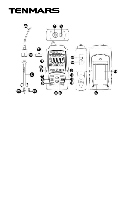
4 Meter Description
1. Accelerometer input terminal
2. LED work light.
3. LCD display screen
4. Maximum hold and data hold button
5. Power switch button
6. Backlight button
7. Function selection button
8. Left button/REC record button
9. Settings function button
10. Down button
11. Confirm button/LED work light control button
12. Right button/MEM view record value button
13. UNIT unit selection button
14. Up button
15. External power DC 9V input
16. USB data output jack (ST-140D)
17. Battery installation
18. Battery cover and stand
19. Accelerometer
20. Low noise cable
21. Magnetic base
22. Handheld probe
23. pointed probe
24. round probe
Page 5
ST-140/ST-
140D
3
5 Operation
1. Connect the accelerometer with the magnetic base
and lock one side of the cable; connect the other end
of the cable with the accelerometer input terminal of
the meter, and then attach the accelerometer to the
test object.
2. Another measuring method is to connect the
accelerometer with the handheld probe and lock one
end of the cable, and then connect the other end of
the cable with the accelerometer input terminal of the
meter and use the handheld probe to test the test
object.
3. Press the button once to turn it ON or OFF;
pressing the button for over 2 seconds under
power ON status will cancel automatic shutdown and
turn OFF the automatic shutdown symbol on the LCD.
* The power cannot be turned OFF under SETUP
mode; please exit SETUP mode first.
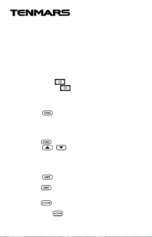
4. The button selects the measuring status:
acceleration (ACC) real value (RMS) → acceleration
(ACC) peak value (PEAK) → velocity (VEL) real value
(RMS) → velocity (VEL) peak value (PEAK) →
displacement (DISP) peak to peak value (P-P). The
measuring status changes once every time
the button is pressed.
5. The or button can be used under
acceleration (ACC) measurement status to select HI
or LO gear (the measuring frequency of the HI gear is
10Hz~5KHz, and the measuring frequency of the LO
gear is 10Hz~1KHz (after filtering circuit; complies
with ISO 2954).
6. The button selects the measuring unit; the
measuring unit changes once every time
the button is pressed.
7. Reading measured value on LCD.
8. If you are at a dark location, you can press
the button for over 2 seconds to turn ON the LED
to use as auxiliary lighting; to cancel this function,
press the button for over 2 seconds again.
Page 6
ST-140/ST-
140D
4
5.1 Turn ON backlight
Under power ON status, press the button to turn ON
the backlight, and then press the button again to turn
OFF the backlight function directly.
*The backlight will automatically turn OFF after being lit for
15seconds.
5.2 Datalogging Single Sata Entry Manually:
Press the button to save 1 data entry; the “REC”
symbol and entry number will be displayed on the LCD. For
example: 0001; every time the button is pressed, this
number will increase by 1.
5.3 Reading Record Data In Memory:
To read the data recorded on this instrument, please first
press the button; now the “MEM” symbol will appear
on the LCD and it has now entered memory data reading
mode. To read other memory data entries, you can press
the button and the number of entry will increase, or
press the button and the entry number will decrease.
When you want to exit the memory data reading mode,
please press the button for over 2 minutes to exit this
mode.
5.4 Data Hold And Maximum Read Value:
To lock the read value on the LCD while measuring, press
the button to lock the read value; now the “HOLD”
symbol will be displayed on the LCD. Press the button
again to lock the maximum read value; now the “MAX
HOLD” symbol will be displayed on the LCD. To exit this
function, please press the button for over 2 seconds.
5.5 Auto Power Off:
Press the button more than 2 seconds to turn on or
turn off auto power off.
Page 7
ST-140/ST-
140D
5
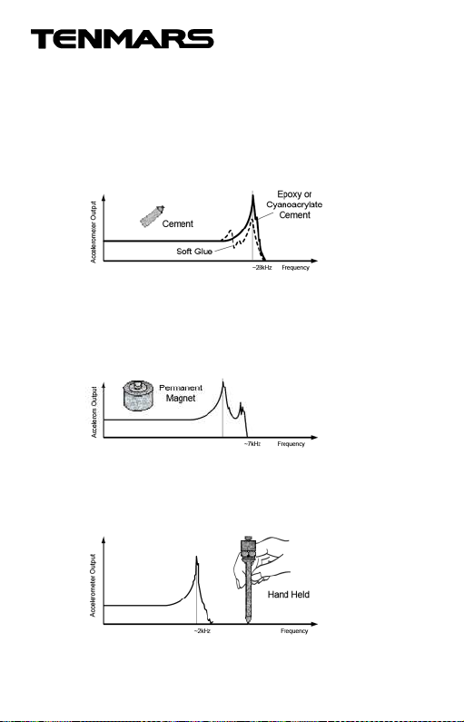
5.6 Accelerometer Installation:
When a permanent measuring point needs to be created on
a machine but you do not want to drill holes on the machine,
bonding studs can be used. These studs can be fixed on
the measuring point using hard adhesives; we recommend
using epoxy and cyanoacrylate agents because soft
adhesives will reduce the useful frequency range of the
accelerometer significantly.
When the measuring point is a flat surface, a permanent
magnet seat can be used for simple installation. This
method will reduce the resonant frequency of the testing
accelerometer to 7KHz; therefore, it cannot be used for
measurements much higher than 2KHz. The suction of the
magnet can tolerate up to 1000 to 2000m/s² vibration force,
depending on the size of the accelerometer.
Installing the accelerometer on top of a handheld probe is
convenient for quick checks, but it will cause considerable
measurement errors due to the decrease in overall firmness,
so do not expect repeatable results. A low-pass filter should
be used in order to restrict the measuring range to
approximately 1000Hz.
Page 8
ST-140/ST-
140D
6
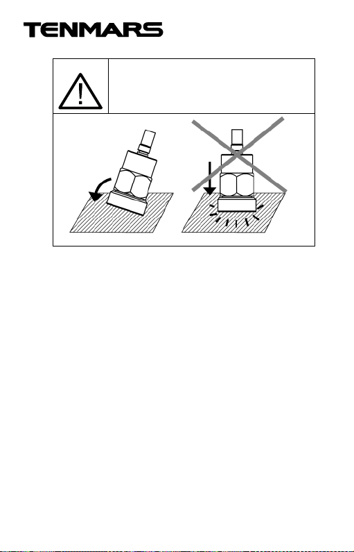
Put on the sensor with the magnetic
base to the measuring point like shown
in below by gently rolling it over the
edges. Avoid magnet breakdown.
Page 9
ST-140/ST-
140D
7
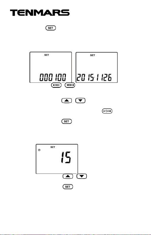
5.7 Function Settings: Step 1~Step 6
Press the button for over 2 seconds to enter the
Step1~Step 7 settings.
STEP 1. Setting date and time:
1. Entering date and time setting mode.
2. Press the or button to select the item to
change; the number of the selected item will start
flashing.
3. Then press the or buttons to change the
preset value.
4. To exit this setting function, press the button for
over 2 seconds to save the settings and exit this mode.
5. Then press the button to enter Step 2.
STEP 2. Setting automatic shutdown time:
1. Set automatic shutdown mode; now the number will
now start flashing.
2. Then press the or buttons to change the
value (the unit is 01~99 minutes).
3. Then press the button to enter Step 3.
Page 10
ST-140/ST-
140D
8
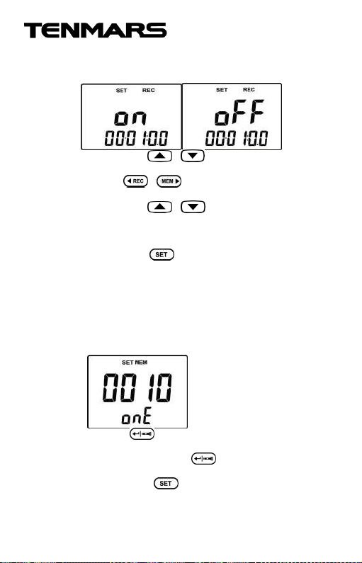
STEP 3. Setting automatic record time:
1. Set whether to enable automatic record time mode;
now OFF or ON will start flashing on the LCD.
2. Then press the or buttons to change whether
to turn the automatic record mode ON or OFF.
3. Press the or buttons to select the item to
change.
4. Then press the or button to change the
automatic record time.
5. To turn OFF automatic record mode after it is turned
ON, please return to Step 3 and change ON to OFF.
6. Then press the button to enter Step 4.
STEP 4. Clearingsingle memory record data
entry:
1. Steps 4 and 5 will not appear if there is no recorded
data, and it will skip directly to Step 7.
2. Enter clear single memory record data entry mode;
now the entry number will be displayed on the LCD
and onE will start flashing.
3. Press the button and the entry number
displayed on the LCD will be reduced by one, and
onE will flash; press the button again to clear the
next data entry.
4. Then press the button to enter Step 5.
Page 11
ST-140/ST-
140D
9
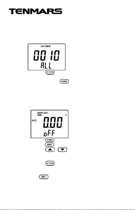
STEP 5. Clear all recorded memory data (ALL):
1. Steps 4 and 5 will not appear if there is no recorded
data, and it will skip directly to Step 7.
2. Enter clear all memory record data mode (ALL); now
the number of data entries will be displayed on the LCD
and ALL will start flashing.
3. Press the button once and the number of data
entries will be displayed on the LCD and CLr will start
flashing; press the button again to confirm and
enter Step 6.
STEP 6. Resettingto zero
1 Enter connection interface setting mode; now the SET
and ZERO symbols will be displayed on the LCD and
“oFF” will start flashing.
2 Press the button to select the function to reset and
press the button to select the unit to reset to zero.
3 Press the or button to select ON or OFF; ON
must be selected to perform the reset action and it will
start flashing when selected.
4 Press the button and this meter will automatically
read the value to reset to zero and display it on the
LCD.
5 Press to exit setting mode and enter measuring
mode.
Page 12
ST-140/ST-
140D
10
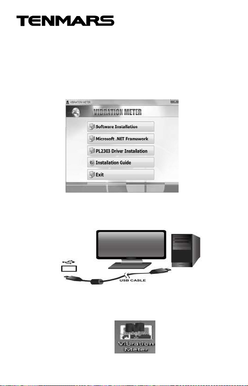
6 Software Installation
Supported operating systems: XP/Windows7/Windows
8.1/Windows10
Downloading PL-2303 execution software:
Place the CD included with this meter into the
CD/DVD-ROM drive of the PC to connect to and install
the desktop program:
Execute the PC desktop software program:
Connect the USB cable included with this meter to the
PC, as shown in the figure below.
Double-click the left mouse button on the desktop
program (Thermometer Meter) to execute the desktop
program.
Page 13

ST-140/ST-
140D
11
7 General Specifications
Themaximum display of the LCD is 1999.
Measurementitem: VEL (velocity) / ACC (acceleration) /
DISP (displacement).
Function: Acceleration (RMS, PEAK, MAX HOLD, HOLD).
Unit:Acceleration: m/s², g, ft/s². Velocity: mm/s, cm/s,
inch/s. Displacement: mm, inch.
Frequency features: LO range: 10Hz~1KHz. Complies
Auto power (15 minutes) and disable auto power off.
Overload display: “OL”.
Manual 200 records.
Datalogging capacity 9999 records. (ST-140D)
Low battery detection “ ”.
Battery: 1.5V×6 (LR03 SIZE AAA 1.5V).
Batterylife: Approximately 100 hours.
Powerconsumption: Approximately less than 15mA.
Accelerometer operating temperature: -20°C to 70°C.
Operating temperature and humidity of meter: -10°C to
50°C, relative humidity under 90%.
Storage temperature and humidity: -10°C to 50°C,
relative humidity under 70%.
Weight:Approximately 400 grams (including holster and
accelerometer).
Dimensions: 156 (L) x 73 (W) x 35 (H) mm.
AC to DC Adaptor
Velocity (RMS, PEAK, MAX HOLD, HOLD).
Displacement (P-P, MAX HOLD P-P, HOLD).
with international specification ISO
2954-2012.
HI range: 10Hz~5KHz.
External AC 100~240V to DC 9V/0.5A power supply.
Plug: The pin in the center connects to the positive
electrode and the outer case is negative electrode.
Diameter: 5.5mm; internal diameter: 2.1mm.
Page 14

ST-140/ST-
140D
12
2
2
2
2
8 Electrical Specifications:
Accurate environmental conditions are: 23°C ± 3°C and RH <80%
Acceleration (RMS,PEAK,MAX HOLD) 1g=9.81m/s2
Range 0.5~199.9
m/s
Resolution 0.1 m/s² 0.01g 1 ft/s
Accuracy ± (5%+5d)
@79.4Hz
and158Hz
Calibration
point
50m/s
(158Hz)
Velocity VEL (RMS, PEAK, MAX HOLD)
Range 0.5~199.9
mm/s
Resolution 0.1 mm/s 0.01cm/s 0.01
Accuracy ± (5%+5d)
@79.4Hz
and158Hz
Calibration
point
50mm/s
(158Hz)
Displacement DISP (P-P, MAX HOLD P-P)
Unit mm inch
Range 0.005~1.999 mm 0.002~0.078 inch
Resolution 0.001 mm 0.001 inch
Degree of
error
± (5%+5d)
@79.4Hz
and158Hz
Calibration
point
0.141mm
(158Hz)
0.05~20.39g2〜656
2
± (5%+5d)
@79.4Hz
and158Hz
50m/s
(158Hz)
0.05~19.9
9
cm/s
± (5%+5d)
@79.4Hz
and158Hz
50 mm/s
(158Hz)
@79.4Hz and158Hz
0.141mm (158Hz)
ft/s
± (5%+5d)
@79.4Hz
and158Hz
50m/s
(158Hz)
0.02~7.87
inch/s
inch/s
± (5%+5d)
@79.4Hz
and158Hz
50 mm/s
(158Hz)
± (5%+5d)
2
Page 15

ST-140/ST-
140D
13
9 Maintenance or Repair
1.When the When “ ” symbol is displayed on the LCD, it
means that there is insufficient power; please change the
battery immediately in order to ensure its accuracy.
2.Do not place the meter in locations that have high
temperature, humidity or that are exposed to direct
sunlight.
3.Remember to turn off the power after usage; remove the
battery if not used for a long period of time in order to
prevent battery leakage and causing damages to internal
components.
4.When the instrument failure, only by the authorized
service provider or return the original repair.
10 Battery Replacement
1. Turn off the power.
2. Open the frame and battery cover at the back of the
meter, remove the batteries.
3. Please insert six new AAA 1.5V batteries according to
the polarities.
4. Put the battery cover and frame back in place.
11 End of Life Disposal
Note: This symbol indicates that the meter
and its accessories must be separated and
processed properly.
Page 16

TENMARS ELECTRONICS CO., LTD.
6F, NO.586 Ruiguang Rd, Neihu Dist.
http://www.ten
mars.com
Taipei City, Taiwan
E-mail: [email protected]
 Loading...