

Tenma ST-8920 User Manual
TM
TM
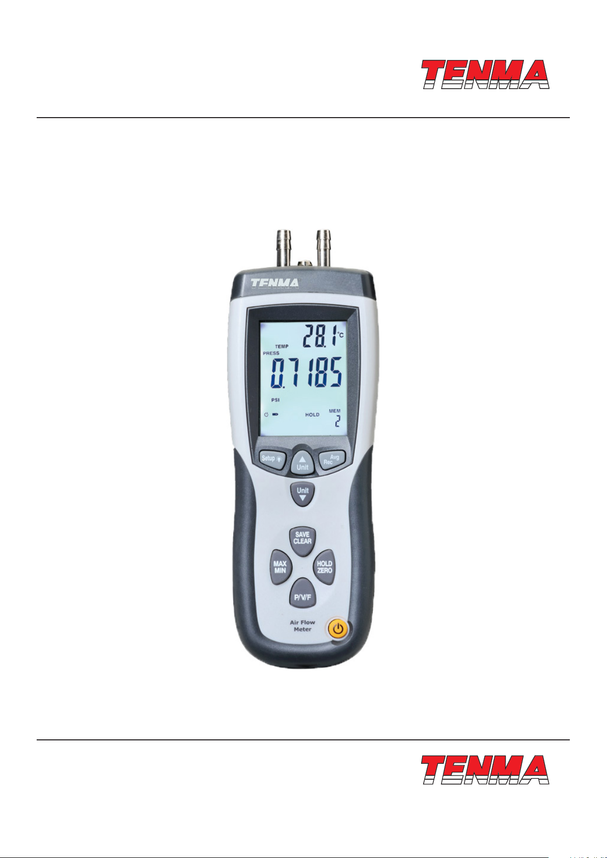
Pressure & Flow Meter
User Manual
www.element14.com
www.farnell.com
www.newark.com
www.cpc.co.uk
Part Number: ST-8920
Page <1>
V1.012/04/18

TM
TM
Table of Contents
1. Features .................................................................................................................... 3
2. Specications .......................................................................................................... 3
3. Button ....................................................................................................................... 4
4. Display Elements ..................................................................................................... 5
5. Changing Setup Options ......................................................................................... 6
5-1. Setup Options ...........................................................................................................................................6
5-2. Entering or Exiting Setup ........................................................................................................................6
5-3. Changing a Setup Option ........................................................................................................................6
5-4. Duct dimension units Setting .................................................................................................................6
5-5. Duct Shape and Parameters Setting ......................................................................................................7
5-6. Choose Duct Shape .................................................................................................................................7
5-7. Parameters Setting ..................................................................................................................................7
5-8. Auto Power Off Mode ...............................................................................................................................8
5-9. Menu Setting .............................................................................................................................................8
5-10. Ciear Memory Setting ............................................................................................................................9
5-11. Measuring Pressure ...............................................................................................................................9
5-12. Measuring Velocity ...............................................................................................................................10
5-13. Measuring Flow ....................................................................................................................................10
5-14. Displaying Temperature ......................................................................................................................11
5-15. Holding the Displayed Readings ........................................................................................................11
5-16. Viewing the MIN, MAX, and AVG Readings ........................................................................................11
5-17. Saving Samples .................................................................................................................................... 11
5-18. Recall and Clearing Sample Data .......................................................................................................11
5-19. Error Codes ..........................................................................................................................................12
5-20. Replacing the Batteries .......................................................................................................................12
www.element14.com
www.farnell.com
www.newark.com
www.cpc.co.uk
Page <2>
V1.012/04/18
TM
TM
1. Features
• Larger LCD display with backlight.
• Relative time clock on MAX, MIN and AVG provides a time reference for measurement.
• Pressure, velocity or air ow measurement provides Zero Adjust.
• Display pressure, Air velocity or air ow plus environment Temperature simultaneously.
• Easy to calculate the area of a rectangular or circular duct.
• USB interface, USB to UART Bridge Controller.
• Low battery indication, and Auto Power Off mode (Sleep mode) increases.
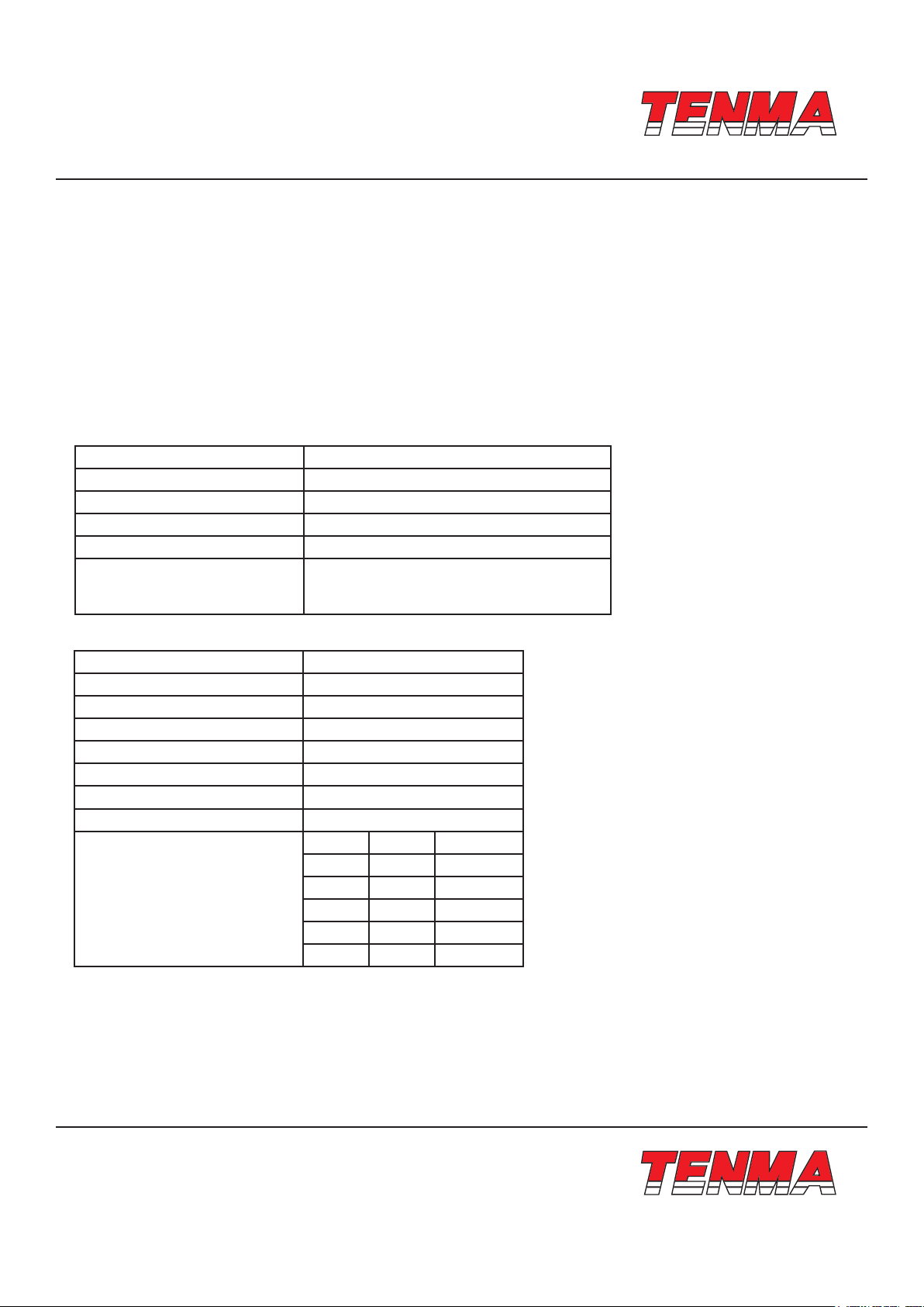
2. Specications
2-1. General Specications
Operating Conditions 0°C to 50°C
Storage Conditions -10°C to 60°C
Power Supply 1×9V Battery
Low Battery Indicator Yes
Dimensions 203mm×75mm×50mm
Relative Humidity Non condensing (<10°C) 90% RH
(10°C to 30°C)75% RH (30°C to 40°C) 45% RH
(40°C to 50°C)(Without Condensation)
2-2. Manometer specication
Accuracy ±0.3% FSO(25°C)
Repeatability ±0.2% (Max.±0.5% FSO)
Linearity/Hysteresis ±0.29% FSO
Pressure Range 5000 Pa
Maximum Pressure 10psi
Response Time 0.5 Seconds typical
Over range Indicator Err.1
Under range Indicator Err.2
Units Range Resolution
PSI 0.7252 0.0001
mbar 50 0.01
inH20 20.07 0.01
mmH20 509.8 0.1
Pa 5000 1
1 psi*27.68=inH20
1 psi*68.947=mbar
1 psi*703.072= 1*mmH20
1 psi*6894.6=Pa
FSO: Full Scale Output
www.element14.com
www.farnell.com
www.newark.com
www.cpc.co.uk
Page <3>
V1.012/04/18

TM
TM
2-3. Range of Air Velocity
Air Velocity Range Resolution Accuracy
m/s(meter per second) 1-80 0.01
ft/min(feet per minute) 200-15733 1
km/h(kilometers per hour) 3.6-288 0.1
MPH(miles per hour) 2.24-178.66 0.01
Knots(nautical miles per hour) 2-154.6 0.1
2-4. Rang of Air Flow
Air Flow Range Resolution
CFM 0-99.999ft3/min 0.0001 to 100
CMM 0-99.999m3/min 0.001 to 100
CFM(ft3/min) =Air Velocity(ft/min)×Area(ft2)
CMM(m3/min)=Air Velocity(m/s)×Area(m2)×60
CFM: cubic feet per minute
CMM: cubic meters per minute
2-5. Range of Temperature
Range Resolution Accuracy
°C 0°C to 50°C 0.1 ±1°C
°F 32°F to 122°F 0.1 ±2°F
±2.5% of reading
at 10 m/s
Accuracy is function
0.1 of velocity and
duct 0.01 size
3. Button
1. Press to turn the thermometer on or off.
2. Press “MAN/MIX” to step through the maximum, minimum, and average readings. To exit the MAN/MIX/AVG mode,
press the “MAN/MIX” button for 2 seconds to return to normal operation.
3. Press “P/V/F” to show the air velocity, press “P/V/F” secondly to show the high and length of a rectangular or the
diameter circular duct, press “P/V/F” thirdly to show the air ow, press “P/V/F” to show differential pressure again.
4. Press “Hold/Zero” to freeze or unfreeze the displayed readings. Press “Hold/Zero” button and hold 2 seconds to
zero out the display.
5. Press “Save/Clear” button to store sample data. Or press “Save/Clear” button to clear sample data in Recall mode.
6. Press “Setup ” button to turn on the backlight. Press it again to turn off the backlight. Press “Setup ” button for
3 seconds to start or exit Setup. (See “Changing Setup Options.”)
7. Press “Unit ” to changes the temperature units. In Setup mode, press “Unit ” to scroll to the Setup option you want
to change or press “Unit ” to increase the displayed setting. In Recall mode, press “Unit ” to select the desired
sample number.
8. Press “Unit ” to Changes secondly showing number units. In Setup mode, press “Unit ” to scroll to the Setup
option you want to change or press “Unit ” to increase the displayed setting. In Recall mode, press “Unit ” to select
the desired sample number.
9. Press “Avg/Rec” button and hold 2 seconds to enter Recall mode. In Recall mode, press “Avg/Rec” to calculate the
sample data. In Setup mode, press “Avg/Rec” button to enter a Setup option. Press “Avg/Rec” again to store the
displayed setting in memory.
www.element14.com
www.farnell.com
www.newark.com
www.cpc.co.uk
Page <4>
V1.012/04/18
 Loading...