

Page 1
72-9490
Page 2

TABLE OF CONTENTS
TITLE
PAGE
72-9490: OPERATING MANUAL
1
Overview
Unpacking Inspection
Safety Information
Rules For Safe Operation
International Electrical Symbols
The Meter Structure
A.The Meter Front Structure
B.The Meter Back and Bottom Structure
Functional Buttons
Display Symbols
Measurement Operation
A. AC Voltage + Frequency Measurement
B. AC Current + AC Voltage Measurement
C. Active Power + Phase Angle Measurement
D. Apparent Power + Reactive Power Measurement
E. Power Factor + Phase Angle Measurement
F. Active Energy + Time Measurement
True RMS Measurement and Average Value Measurement
Specifications
3
4
5
6
8
9
9
11
12
15
17
17
19
20
28
30
32
33
35
Page 3

2
35
36
37
37
37
37
38
39
40
40
41
41
42
42
43
72-9490: OPERATING MANUAL
TABLE OF CONTENTS
TITLE PAGE
A. General Specifications
B. Environmental Requirements
Accuracy Specifications
A. AC Voltage
B. Frequency
C. AC Current
D. Active Power
E. Apparent Power
F. Reactive Power
G. Power Factor
H. Phase Angle
I. Active Energy
Maintenance
A. General Service
B. Replacing the Battery
Page 4

72-9490: OPERATING MANUAL
3
The Meter can measure Voltage, Current, Active Power, Apparent Power, Reactive Power, Power Factor, Phase Angle,
Frequency, Active Energy and etc.
Model 72-9490 is a three phase intelligent handheld digital power clamp meter (hereafter referred to as “the Meter”)
which has both the features of digital current meter and also power measurement meter.
Warning
This Operating Manual covers information on safety and cautions. Please read the relevant information carefully
and observe all the Warnings and Notes strictly.
Overview
To avoid electric shock or personal injury, read the “Safety Information” and “Rules for Safe Operation” carefully before
using the Meter.
Page 5
Item
1
2
3
4
5
6
7
8
9
10
11
12
13
Description
English Operating Manual
Red Test Lead
Black Test Lead
Blue Test Lead
Yellow Test Lead
Red Alligator Clip
Black Alligator Clip
Blue Alligator Clip
Yellow Alligator Clip
USB Interface Cable
Software
Tool Box
1.5V Battery (LR6)
Qty
1 piece
1 piece
1 piece
1 piece
1 piece
1 piece
1 piece
1 piece
1 piece
1 piece
1 piece
1 piece
4 pieces
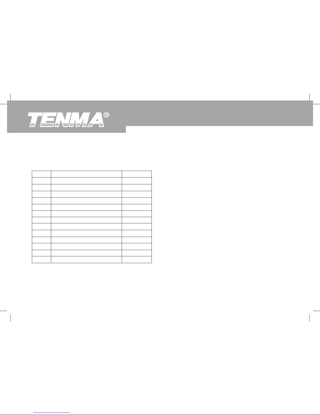
In the event you find any items are missing or damaged, please contact your dealer immediately.
Open the carton and remove the Meter. Check the following items carefully to see if any items are missing or damaged.
Unpacking Inspection
4
72-9490: OPERATING MANUAL
Page 6

72-9490: OPERATING MANUAL
5
This Meter complies with the Safety/ Compliances: IEC 61010 CAT. III 600V, CAT. IV 300V overvoltage and double
insulation standard, pollution degree 2.
CAT. III: Distribution level, fixed installation, with smaller transient overvoltages than CAT. IV
CAT.IV: Primary supply level, overhead lines, cable systems etc.
Use the Meter only as specified in this operating manual to avoid personal injury or damage to your Meter or device under
test.
In this manual, a Warning identifies conditions and actions that pose hazards to the user, or may damage the Meter
or device under test.
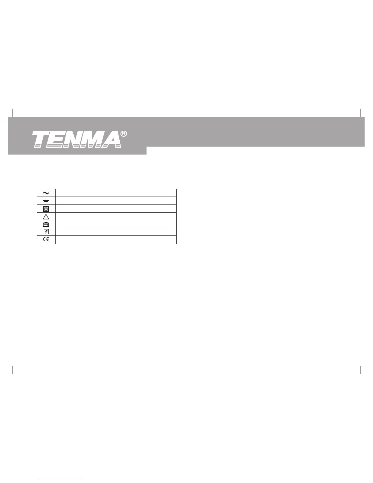
International electrical symbols used on the Meter and in this Operating Manual are explained.
Safety Information
Page 7

6
72-9490: OPERATING MANUAL
Before using the Meter, inspect the case. Do not use the Meter if it is damaged or the case (or part of the
case) is removed. Look for cracks or missing plastic. Pay attention to the insulation around the connectors.
Inspect the test leads for damaged insulation or exposed metal. Replace damaged test leads with identical
model number or electrical specifications before using the Meter.
Do not apply more than the rated voltage, as marked on the Meter.
When your measurements have been completed, disconnect the connection between the test leads and
the circuit under test, remove the test leads from the input terminals of the Meter and turn the Meter
power off.
Do not carry out the measurement when the Meter’s back case and / or battery door is opened to avoid
electric shock.
When the Meter is operating at an effective voltage over 30V in AC, special care should be taken.
Use the proper terminals and function for your measurements.
Do not use or store the Meter in an environment of high temperature, humidity, explosive, flammable
and strong magnetic field. The performance of the Meter may deteriorate if damp or wet.
Do not use the Meter if its surface is wet or the user’s hands are wet.
When using the test leads, keep your fingers behind the finger guards.
Replace the battery as soon as the battery indicator appears. With a low battery, the Meter might
produce false readings that can lead to electric shock and personal injury.
Warning
Rules For Safe Operation
To avoid possible electric shock or personal injury, and to avoid possible damage to the Meter or to the equipment
under test, adhere to the following rules:
Page 8

72-9490: OPERATING MANUAL
7
When opening the battery door, make sure the Meter is off.
When servicing the Meter, use only the same model number or identical electrical specifications
replacement parts.
Do not tamper with the internal circuits of the Meter.
Soft cloth and mild detergent should be used to clean the surface of the Meter when servicing. No abrasive
and solvent should be used to protect the surface of the Meter from corrosion, damage and accident.
The Meter is suitable for indoor use only.
Turn the Meter off when it is not in use and take out the battery when not using for a long time.
Periodically check the battery as it may leak when it has not been in use for some time, replace the battery
if the battery is dead or leaking. A leaking battery will damage the Meter.
Page 9
8
72-9490: OPERATING MANUAL
International Electrical Symbols
AC (Alternating Current)
Grounding
Double Insulated
Warning. Refer to the Operating Manual
Deficiency of Built-In Battery
Danger of High Voltage
Conforms to Standards of European Union
Page 10
72-9490: OPERATING MANUAL
9
1
2
3
4
5
6
7
8
9
10
11
12
13
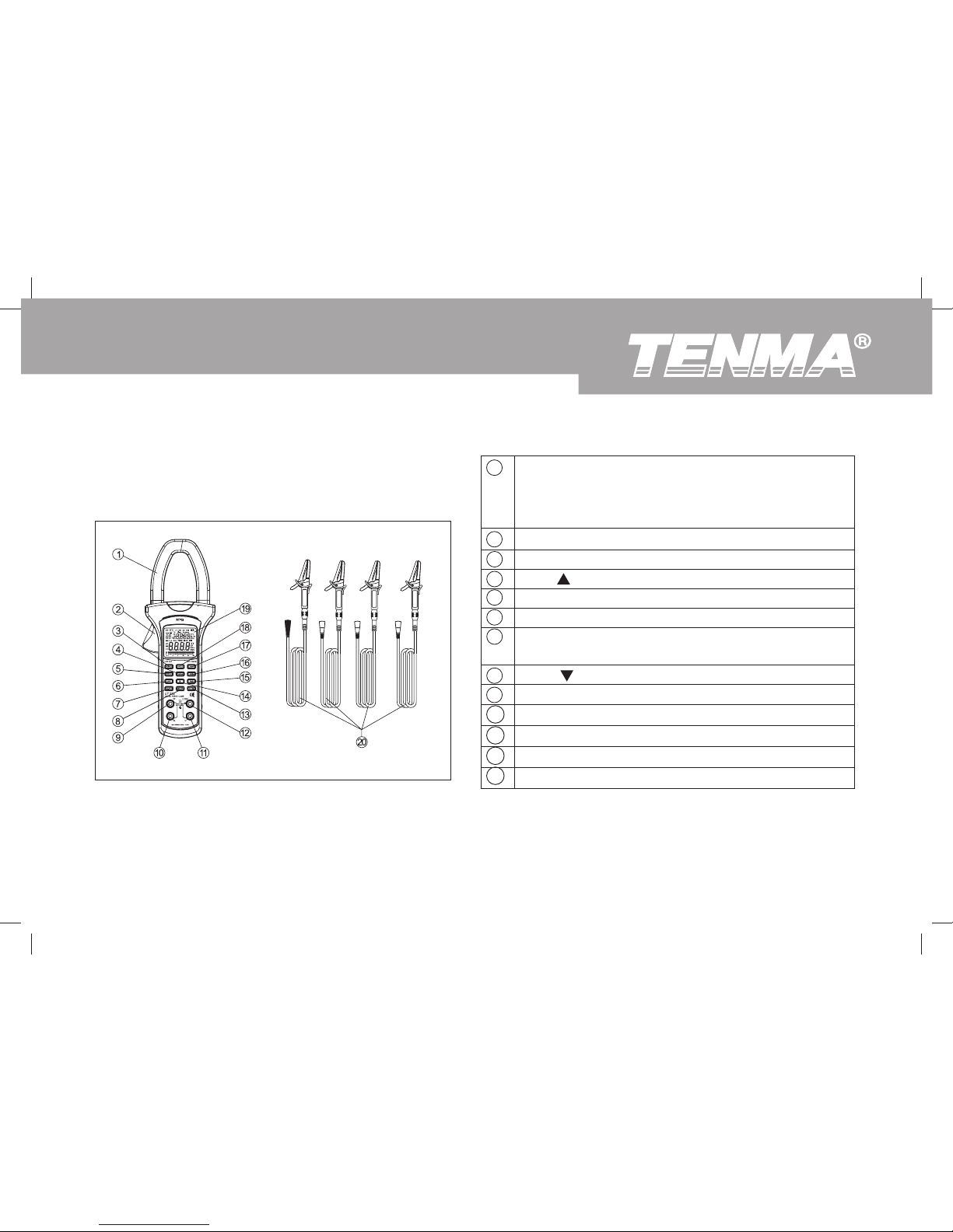
Transformer Jaw: designed to pick up the AC
and DC current flowing through the conductor.
The tested conductor must vertically go through
the Jaw center.
Hand Guards.
Power button
Max/
button
MENU button
LOAD button (recall data)
SELECT button (press to select alternate
function and sum of Watts measurement)
MIN/ button
V3 Input Terminal (Third phase measurement)
V2 Input Terminal (Second phase measurement)
V1 Input Terminal (First phase measurement)
COM Input Terminal
CLEAR button (maximum and minimum)
Figure 1
Black Red Blue Yellow
A. The Meter Front Structure (see figure 1)
The Meter Structure
Page 11
10
72-9490: OPERATING MANUAL
14
15
16
17
18
19
20
Sigma button (Sum)
SAVE button (data store button)
USB button
LIGHT button (auto display backlight button)
HOLD button
LCD Display
Testing Leads (Red, Black, Blue and Yellow)
Page 12
72-9490: OPERATING MANUAL
11
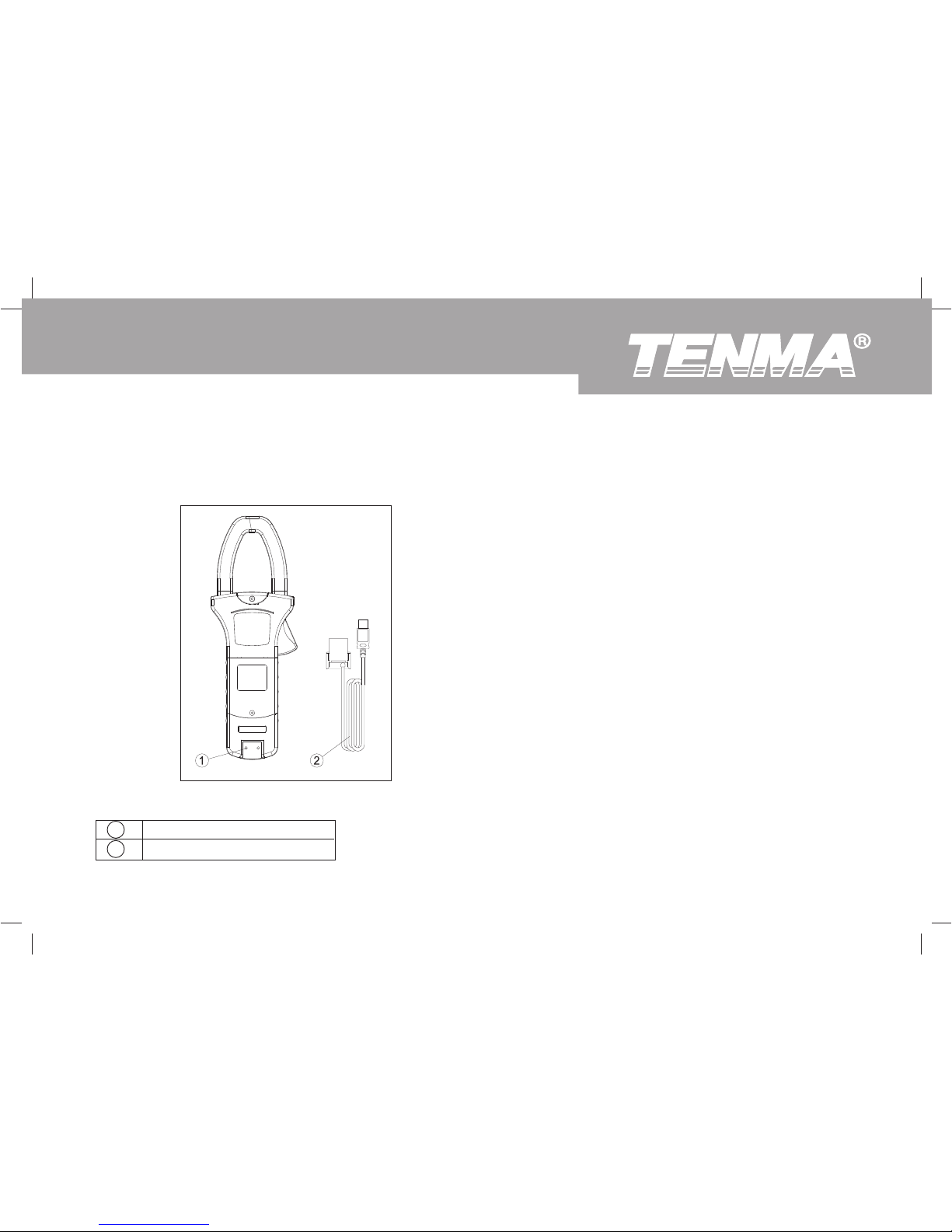
1 Infrared slot
2 USB Interface Cable
Figure 2
B. The Meter Back and Bottom Structure
(see figure 2)
Page 13
12
72-9490: OPERATING MANUAL
MAX/
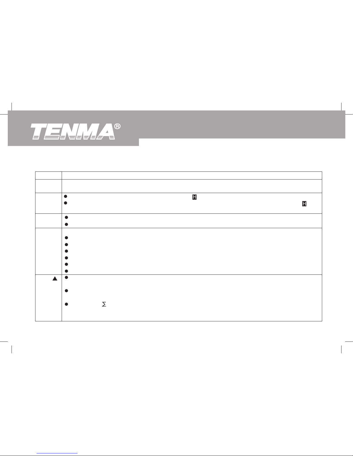
Press MENU to display the following functions in sequence:
AC Voltage (main display) + Frequency (secondary display)
AC Current (main display) + AC Voltage (secondary display)
Active power (main display) + Phase angle (secondary display)
Apparent power (main display) + Reactive power (secondary display)
Power factor (main display) + Phase angle (secondary display)
Active Energy (main display) + Time (secondary display)
Press LIGHT to turn the display backlight on.
The display backlight will be off automatically after 30 seconds.
Press HOLD to enter the Hold mode in any mode, appears and the Meter beeps.
Press HOLD again to exit the Hold mode to return to measurement mode, the Meter beeps and
disappears.
Press and hold POWER for 1 second to turn the Meter on.
Press POWER again to turn the Meter off.
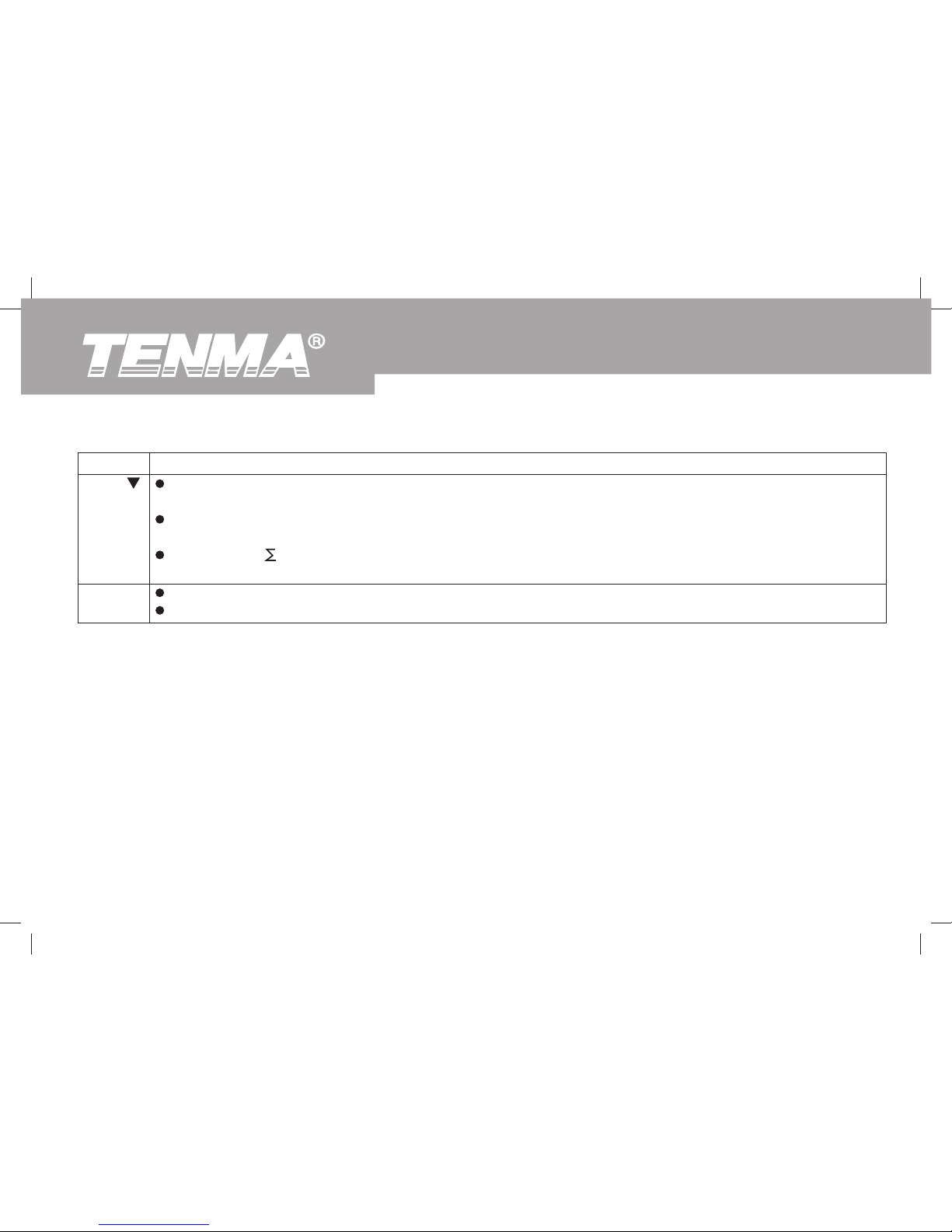
Button
POWER
HOLD
LIGHT
MENU
Operation Performed
The table below describes the function of the main button operations.
Functional Buttons
Press to start recording of maximum value, it valid at voltage, current, active power and apparent power
ranges only.
Press once at LOAD mode, MR icon shown, the Meter displays the next stored reading, the left
secondary display showing the index increase one.
Press once at mode, CAL icon shown, the Meter steps through sum of active power (main display) +
sum of reactive power (secondary display) and sum of power factor (main display) + sum of apparent
power.
Page 14
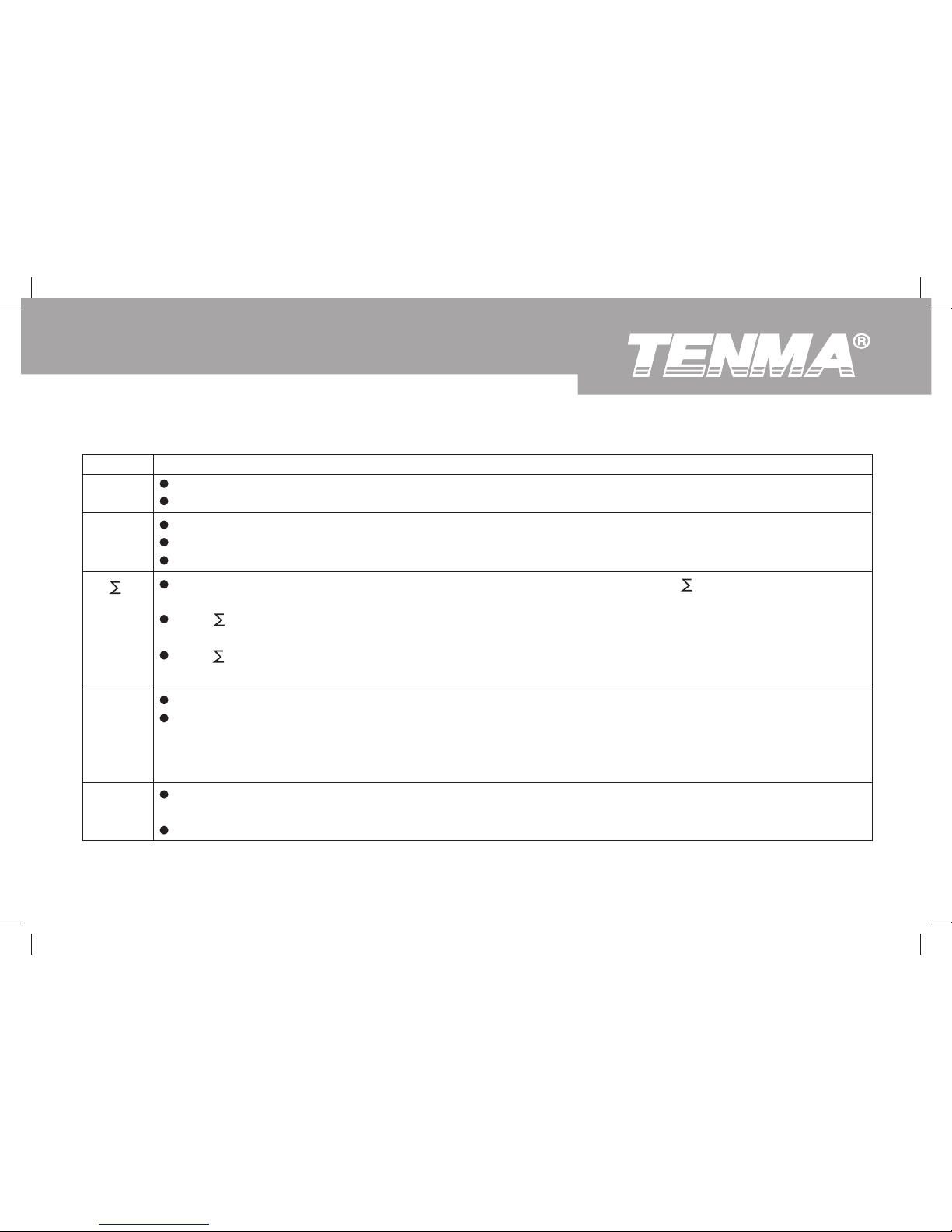
At active power (main display) + phase angle (secondary display) mode, press SELECT button to step
through first phase, second phase, third phase and sum of watts.
At other mode, press SELECT to step through first phase, second phase and the third phase.
At Active power (main display) + Phase angle (secondary display) mode, press once button to sum up the
current first phase of 3 phase measurement result. Then carry out second phase power measurement.
Press again to sum up the second phase power measurement result, then carry out third phase power
measurement.
Press again to sum up the third phase power measurement result, then press SELECT to enter the
measurement of sum of the watts mode, the display shows the 3 phase sum of the watts value.
72-9490: OPERATING MANUAL
13
SELECT
LOAD
Press USB once to turn the USB interface on, USB appears and the Meter beeps.
Press USB again to turn the USB interface off, USB disappears and the Meter beeps.
Press once to enter LOAD mode, MR appears and the Meter beeps.
Press again to exit LOAD mode, MR disappears and the Meter beeps.
Press and hold LOAD for 1 second to display the stored data quickly.
Press once to store single reading, MEM appears and the Meter beeps.
Press and hold for over 1 second to continuous store reading, MEM blinks and the Meter beeps. The index
number shown on the left secondary display keep on increasing. Press SAVE again to exit. The maximum
number of data store is 99, when it achieves 99, the Meter shows FUL. Press CLEAR to clear the stored
reading in order to store next reading.
Button Operation Performed
USB
SAVE
Page 15
14
72-9490: OPERATING MANUAL
At active energy range, press to reset time the zero, then restart the timing.
At all other ranges, press to clear stored readings.
MIN /
Press to start recording of minimum value, it valid at voltage, current, active power and apparent power
ranges only.
Press once at LOAD mode, MR icon shown, the Meter displays the next stored reading, the left secondary
display showing the index decrease one.
Press once at mode, CAL icon shown, the Meter steps through sum of active power (main display) +
sum of reactive power (secondary display) and sum of power factor (main display) + sum of apparent power.
Button Operation Performed
CLEAR
Page 16
72-9490: OPERATING MANUAL
15
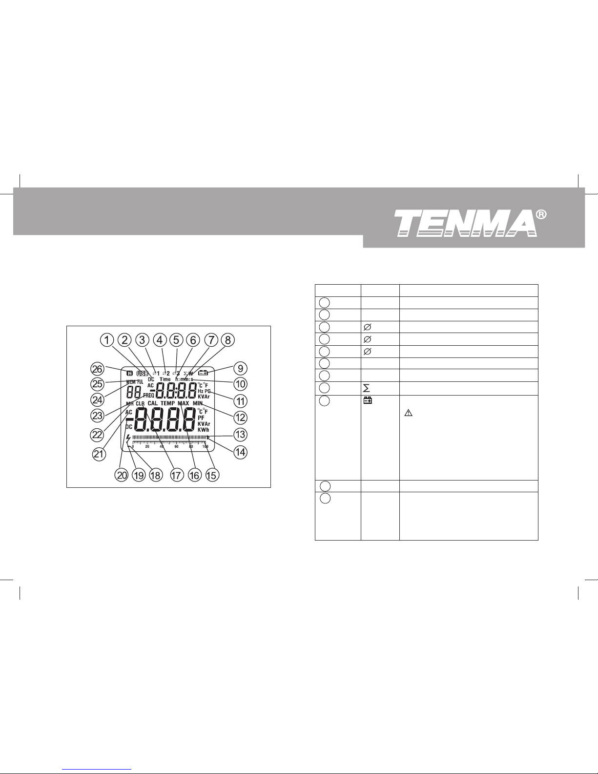
Display Symbols (see figure 3)
Figure 3
1
2
3
4
5
6
7
8
9
10
11
Meaning
Data is transferring via USB
Indicator for DC measurement
First phase symbol
Second phase symbol
Third phase symbol
Unit for hour
Unit for minute
Watt: Sum of Watt
The battery is low.
Warning: To avoid false
readings, which could lead to
possible electric shock or
personal injury, replace the
battery as soon as the battery
indicator appears.
Unit for second
Symbol of Unit.
Hz: Hertz.The unit of frequency.
PG: The unit of phase angle
KVAr. The unit of reactive power
Symbol
USB
DC
1
2
3
h
mm
W
s
Hz,
PG,
KVAr
Number
Page 17
16
72-9490: OPERATING MANUAL
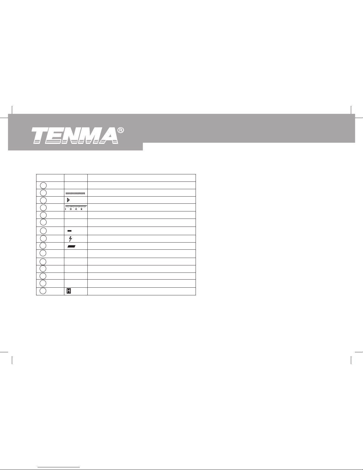
Number
12
13
14
15
16
17
18
19
20
21
22
23
24
25
26
Meaning
Minimum reading
Analog Bar Graph
Overloading
Ruler
Maximum reading
Indicator for clear the stored reading
Ruler negative symbol
High voltage symbol
Indicates negative reading
Indicator for AC voltage or current
Indicator for recall the stored reading
Frequency symbol
Indicator for data store
Indicator for data stored is full
Data hold is active
Symbol
MIN
MAX
CLR
AC
MR
FREQ
MEM
FUL
Page 18
72-9490: OPERATING MANUAL
17
Figure 4
Black
Red
Blue
Yellow
Measurement Operation
Starting Your Meter
Press and hold POWER for one second to turn the
Meter on. The default range is the last measurement
range when you turned off the Meter.
Replace the battery as soon as the battery indicator
“
” appears on the display.
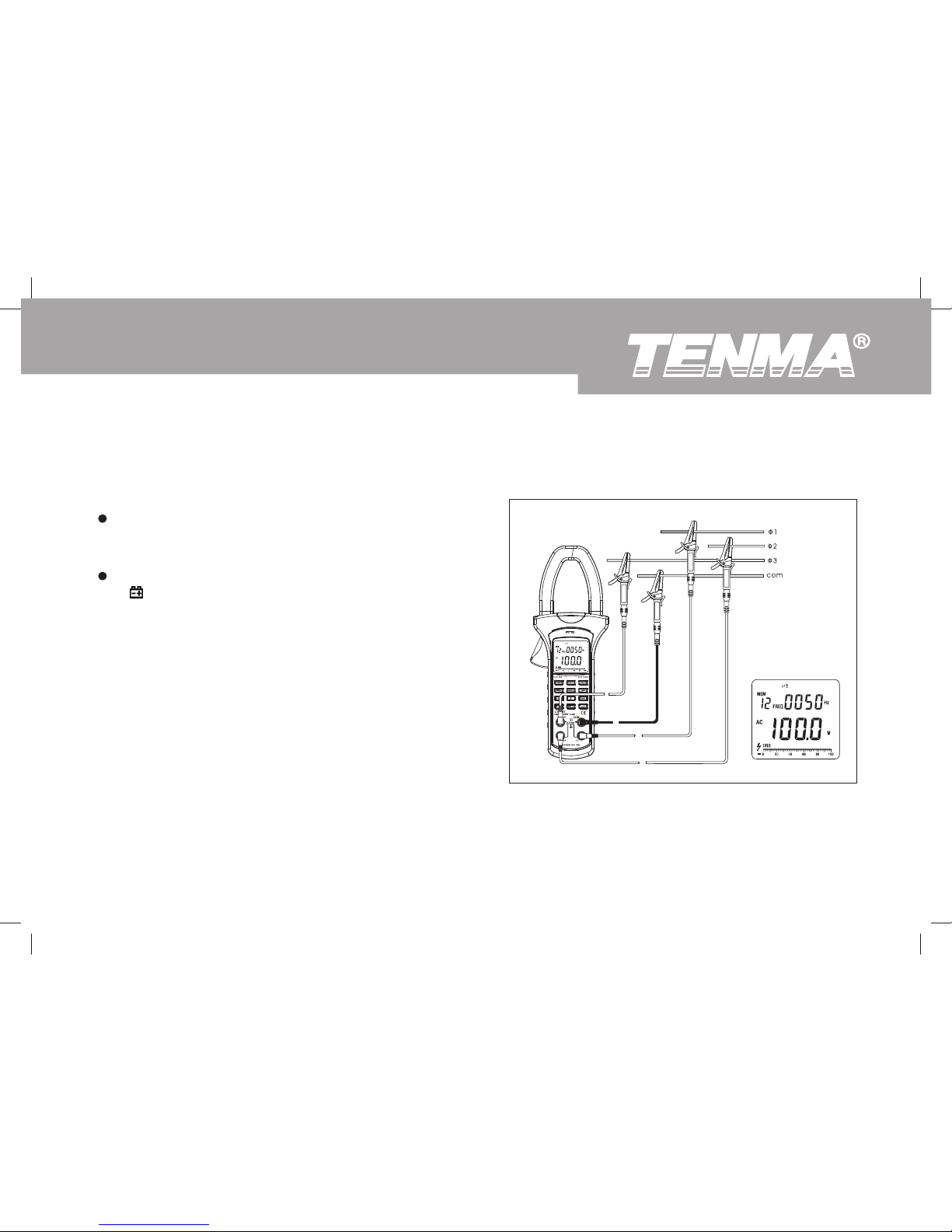
A. AC Voltage (main display) + Frequency
(secondary display) Measurement (see figure 4)
Page 19

18
72-9490: OPERATING MANUAL
1. Insert the red test lead into the V1 terminal, blue test lead into the V2 terminal, yellow test lead to V3 input terminal
and black test lead to the COM input terminal.
2. Press the MENU to select Voltage (main display) + Frequency (secondary display) range.
3. Connect the red test leads ( V1 input terminal), blue test leads ( V2 input terminal) and yellow test leads( V3 input
terminal) to the corresponding three phases loaded live wire. Connect the black test lead (COM input terminal) to
the corresponding three phases loaded neutral wire.
4. Press SELECT to select phase location, the display shows the corresponding phase symbol. V1 means the first phase
1, V2 means the first phase 2, V3 means the first phase 3.
5. The display shows the corresponding True RMS voltage value and frequency value of each phase.
6. Press MAX/ , the LCD displays MAX, it starts recording the maximum AC voltage True RMS value. Press MAX/
again to show the current AC voltage True RMS value.
7. Press MAX/ the LCD displays MAX, it starts recording the minimum AC voltage True RMS value. Press MAX/
again to show the current AC voltage True RMS value.
8. The display shows OL when the input voltage is higher than 600V rms.
Note
When the measurement has been completed, disconnect the connection between the testing leads and the circuit under
test and remove testing leads from the input terminals.
The AC Voltage ranges are:15V, 100V, 300V and 600V
The frequency range is:20Hz~500Hz
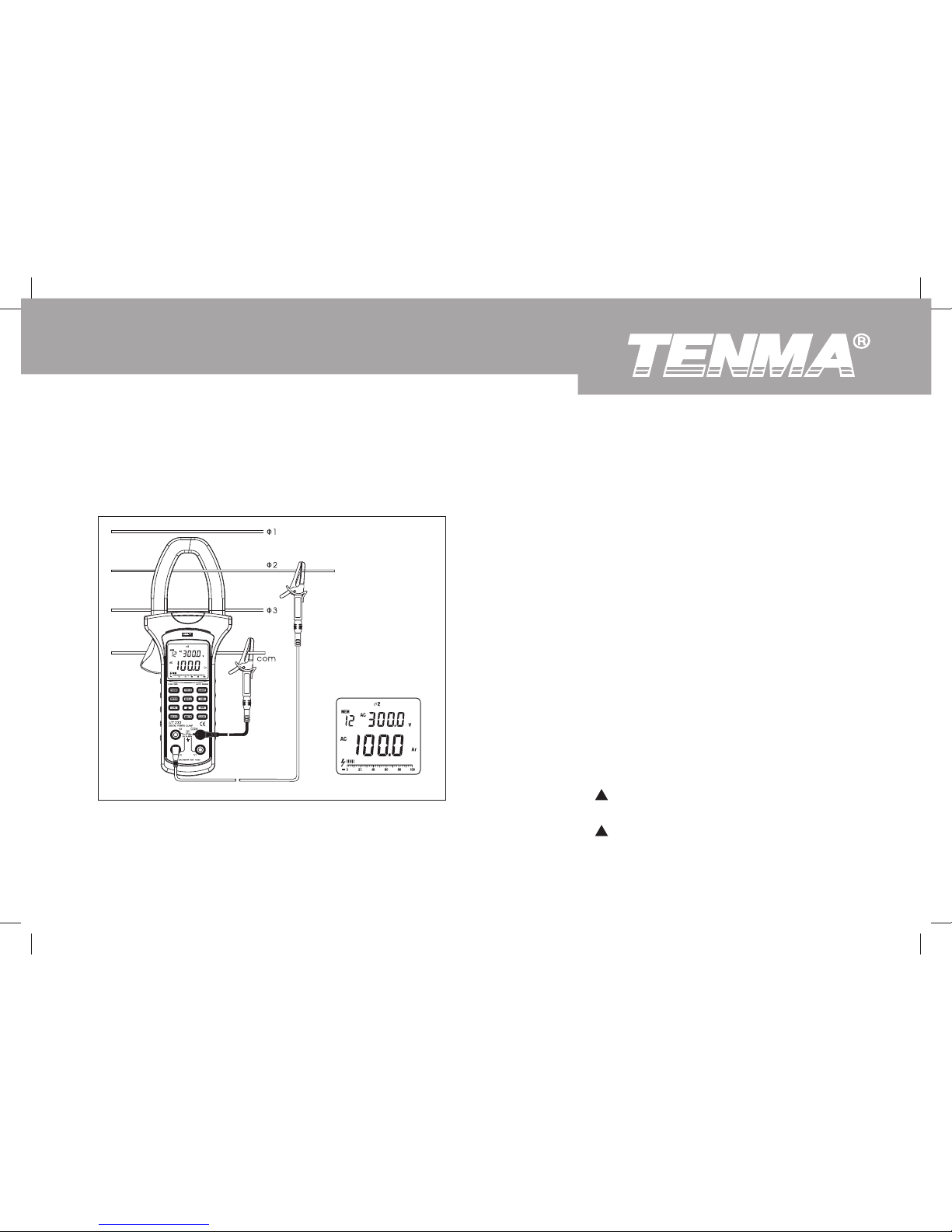
To measure AC voltage + frequency, connect the Meter as follows:
Page 20
72-9490: OPERATING MANUAL
19
1. Press the MENU to select AC Current (main display)
+ AC Voltage (secondary display) range.
2. Press the lever to open the transformer jaw.
3. Center the conductor within the transformer jaw,
then release the Meter slowly until the trasnformer
jaw is completely closed, Make sure the conductor
to be tested is placed at the center of the transformer
jaw, otherwise it will casue deviation. The Meter
can only measure one conductor at a time, to
meausre more than one condutor at a time will
cause deviation.
4. The double display shows the AC current True
RMS value and AC voltage True RMS value.
5. Press MAX/ , the LCD displays MAX, it starts
recording the maximum AC current True RMS value.
Press MAX/ again to show the present AC True
RMS value.
B. AC Current (main display) + AC Voltage
(secondary display) Measurement (see figure 5)
Figure 5
The AC current ranges are: 40A, 100A, 400A and 1000A
The AC Voltage ranges are: 15V, 100V, 300V and 600V
To measure AC current + AC voltage, connect the Meter
as follows:
Black
Blue
Page 21

To avoid damage to the Meter or personal injury, do not exceed AC voltage 600V v.r.s and AC Current
1000A v.r.s.
C. Active Power (main display) + Phase Angle (secondary display) Measurement
The active power ranges are: 40A, 100A, 400A and 1000A
The phase angle ranges are: 0° ~360°
To measure active power + phase angle, connect the Meter as follows:
1. Press the MENU to select Active power (main display) + Phase angle (secondary display) range.
2. Press the lever to open the transformer jaw, and clamp the corresponding lead to the proper conductor to be tested.
If user needs to measure any phase of the 3 phase, then only clamp them to that phase’s conductor.
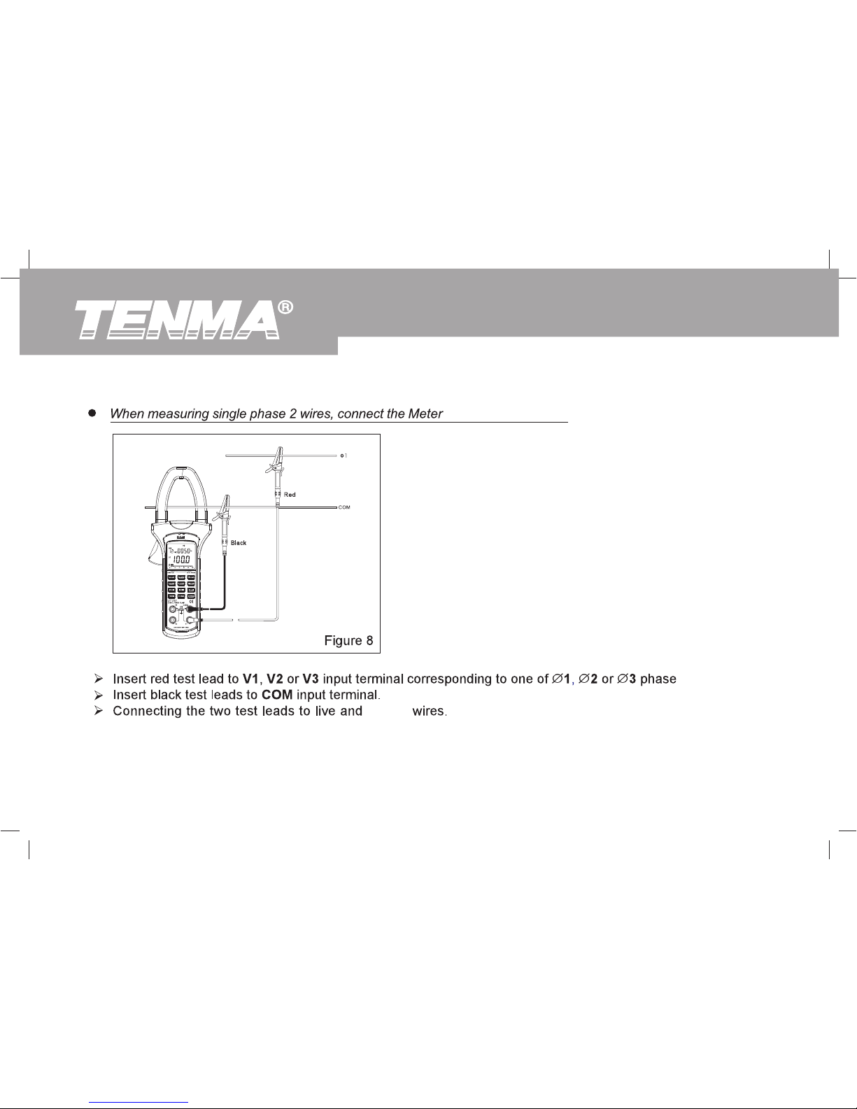
3. Connecting method (see figure 6, 7, 8):
20
72-9490: OPERATING MANUAL
6. Press MIN/ , the LCD displays MAX, it starts recording the minimum AC current True RMS value.
Press MIN/ , again to show the present AC current True RMS value.
7. The display shows OL when the current of the tested conductor is higher than 1000A rms.
Note
When the measurement has been completed, disconnect the connection between the conductor under test and
the jaw, and remove the conductor away from the transformer jaw of the Meter.
Warning
Page 22
72-9490: OPERATING MANUAL
21
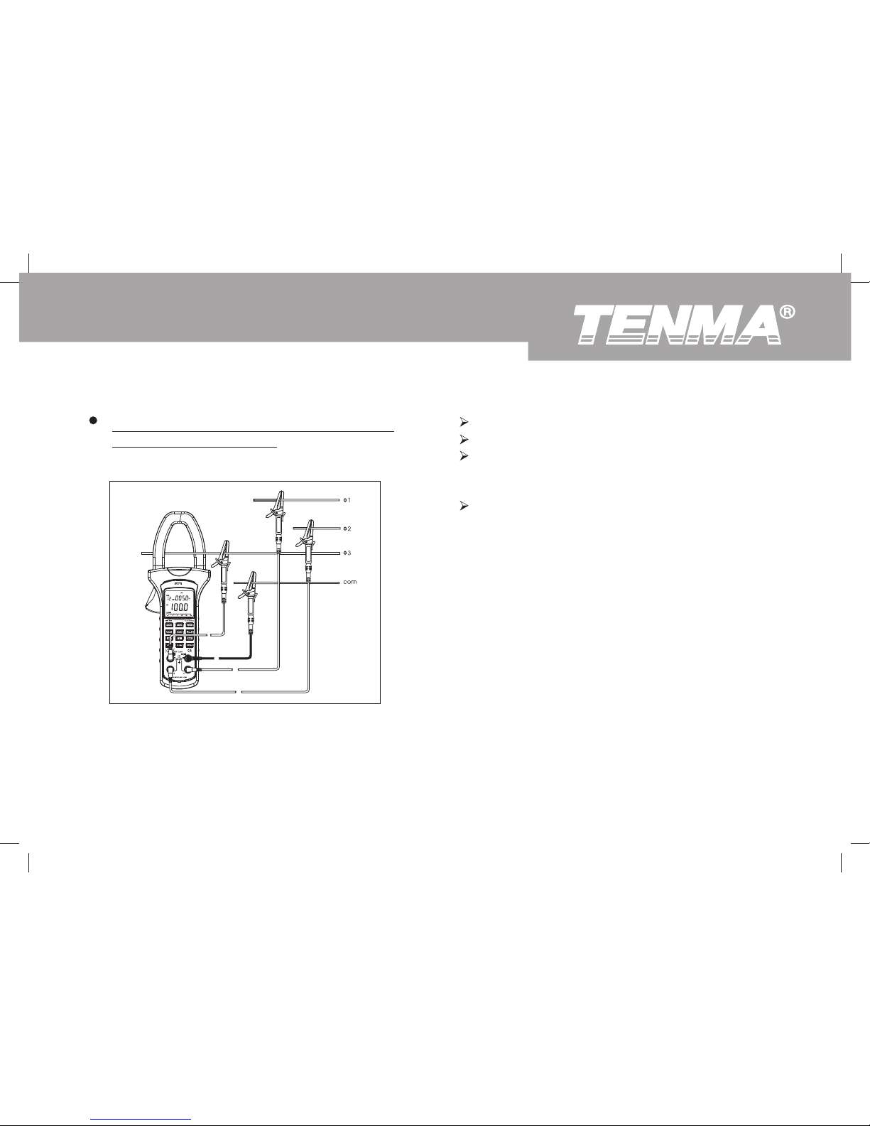
When measuring 3 phase 4 wires, connect the
Meter as shown in figure 6
Figure 6
Black
Red
Blue
Yellow
Insert red test leads to V1 input terminal.
Insert blue test leads to V2 input terminal
Insert yellow test leads to V3 input terminal and
connect each lead to the corresponding live wire
of the 3 phase.
Insert black test leads to COM input terminal and
connect it to the neutral wire of the 3 phase.
Page 23
22
72-9490: OPERATING MANUAL
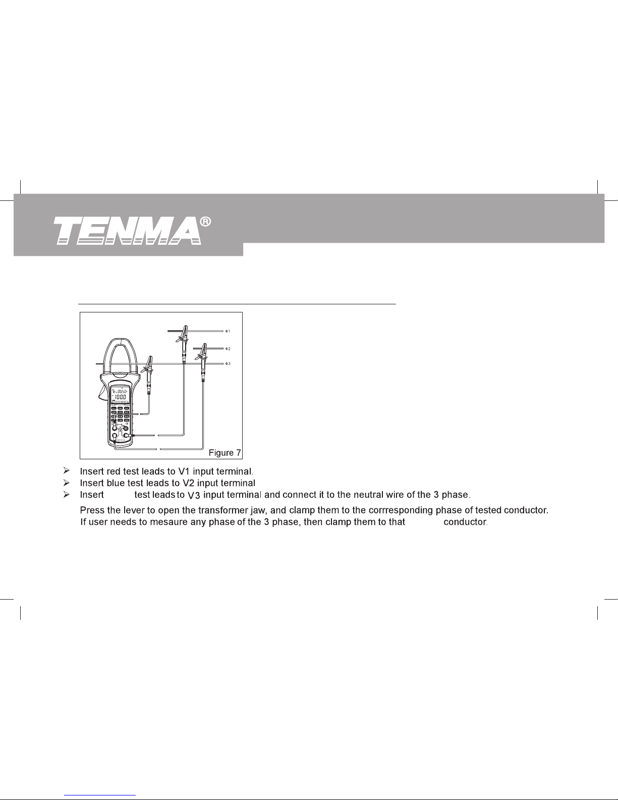
phase’s
2)
yellow
Red
Blue
Yellow
1)When measuring 3 phase 3 wires, connect the Meter as shown in figure 7
Page 24
72-9490: OPERATING MANUAL
23
3)
Page 25
24
72-9490: OPERATING MANUAL
neutral
as shown in figure 8
Page 26
72-9490: OPERATING MANUAL
25
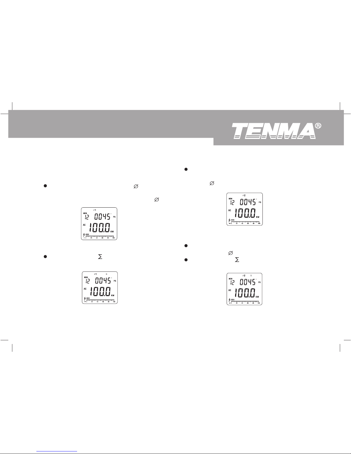
2 as shown in figure 11.
Figure 9
Figure 10
Figure 11
Figure 12
4. When measuring 3 phases 4 wires:
(see figure 9, 10, 11, 12, 13, 14, 15, 16)
Press SELECT to choose phase
1, see as
shown in figure 9. The display show the active
power kW value and also the PG value of 1.
If necessary, press to get the sum of the
power measurement as shown in figure 10.
After summing up the current power measurement
valueof the first phase, then press SELECT to choose
phase
The display shows the value of active power
kW and PG of 2.
If ncessary, press to get the sum of the power
measurement as shown in figure 12
Page 27
26
72-9490: OPERATING MANUAL
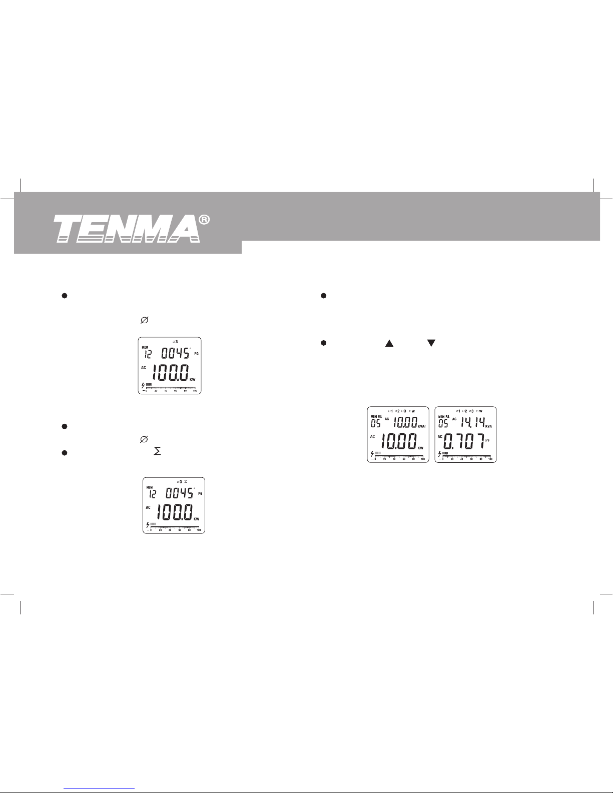
Figure 14
Figure 15
Figure 13
After summing up the current power measurement value
of the second phase, then press SELECT again to
choose tphase 3 as shown in figure 13.
The display shows the value of active power
KW and PG of 3.
If necessary press to get the sum of the power
measurement as shown in figure 14.
After summing up the current power measurement
value of the third phase, finally press SELECT again
to display the three phase sum of active power value
and reactive power value.
Press MAX/ or MIN/ as shown in figure 15 to step
through in sequence three phase sum of active power
and three phase sum of reactive power, and three
phasesumof power factor and three phase sum of
apparent power.
Page 28
72-9490: OPERATING MANUAL
27
6. The maximum power is 600kW of single phase, OL will be displayed when it is over than that. The maximum range
is 1800kW of three phase sum of active power, OL will be displayed when it is over than that.
7. Press MAX/ , the display shows MAX, it starts recording the maximum active power value. Press again to display
the current active power value.
8. Press MIN/ , the display shows MIN, it starts recording the minimum active power value. Press again to display
the current active power value.
Note
When there is no input or single phase, the Meter displays OL, button is not valid.
It can only sum up and save the current measurement value. The maximum and minimum value cannot sum up
and save.
Only at this range can carry out sum of watts measurement, other ranges cannot carry out this measurement.
When testing has been completed, disconnect the connection between the testing leads and the circuit under test
and remove testing leads from the input terminals.
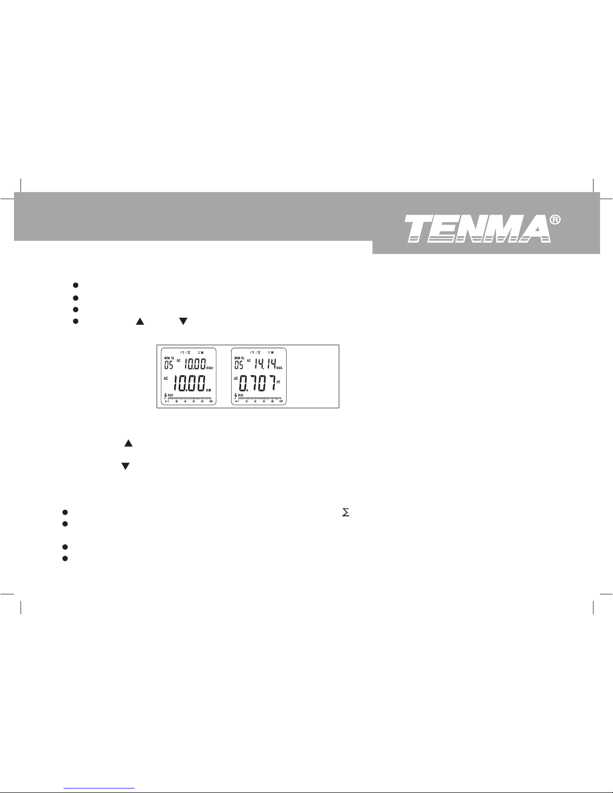
The first and second phase measuring method is same as 3 phase 4 wires.
Jump over the third phase measurement.
Press SELECT to display the 3 phase sum of active power and reactive power.
Press MAX/ or MIN/ as figure 16 to step through in sequence three phase sum of active power and three
phase sum of reactive power, and three phase sum of power factor and three sum of apparent power.
5. When measuring 3 phase 3 wires:
Figure 16
Page 29
To avoid damage to the Meter or personal injury, do not exceed AC voltages of 600V rms and AC
Current of 1000A rms.
28
72-9490: OPERATING MANUAL
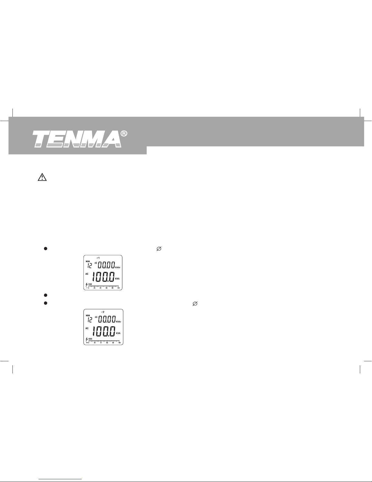
Press SELECTto choose the first phase 1, see figure 17.
To test for Apparent power (main display) + Reactive power (secondary display), connect the Meter as follows:
1. Press the MENU to select Apparent power (main display) + Reactive power (secondary display) range.
2. Press the lever to open the transformer jaw, and clamp them to the corrresponding phase of tested conductor. If
user needs to mesaure any phase of the 3 phase, then clamp them to that phase’s conductor.
3. The connecting method of 3 phases 4 wires, 3 phases 3 wires or single phase 2 wires, see figure 6, 7 and 8
4. When measuring 3 phase 4 wires: (see figure 17, 18, 19)
Warning
D. Apparent Power (main display) + Reactive Power (secondary display) Measurement
Figure 17
The double display shows the first phase value of apparent power kVA and reactive power Kvar.
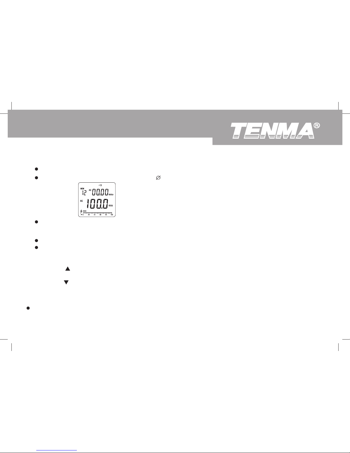
Then press SELECT again to choose the second phase 2, see figure 18.
Figure 18
Page 30
72-9490: OPERATING MANUAL
29
5. When measuring 3 phase 3 wires:
The first phase and secodn phase operating method is same as three phase 4 wires.
Jump over the third phase measurement.
The double display shows the third phase value of apparent power kVA and reactive power Kvar.
Figure 19
Press SELECT again to choose the third phase 3, see figure 19.
The double display shows the second phase value of apparent power kVA and reactive power Kvar.
6. The maximum measuring range is 600kW when measuring single phase apparent power kVA and reactive power Kvar,
OL wil be displayed when it is over than that.
7. Press MAX/ , the display shows MAX, it starts recording the maximum apparent power value. Press again to display
the current apparent power value.
8. Press MIN/ , the display shows MIN, it starts recording the minimum apparent power value. Press again to display the
current apparent power value.
Note
When testing has been completed, disconnect the connection between the testing leads and the circuit under test and
remove testing leads from the input terminals.
Page 31
30
72-9490: OPERATING MANUAL
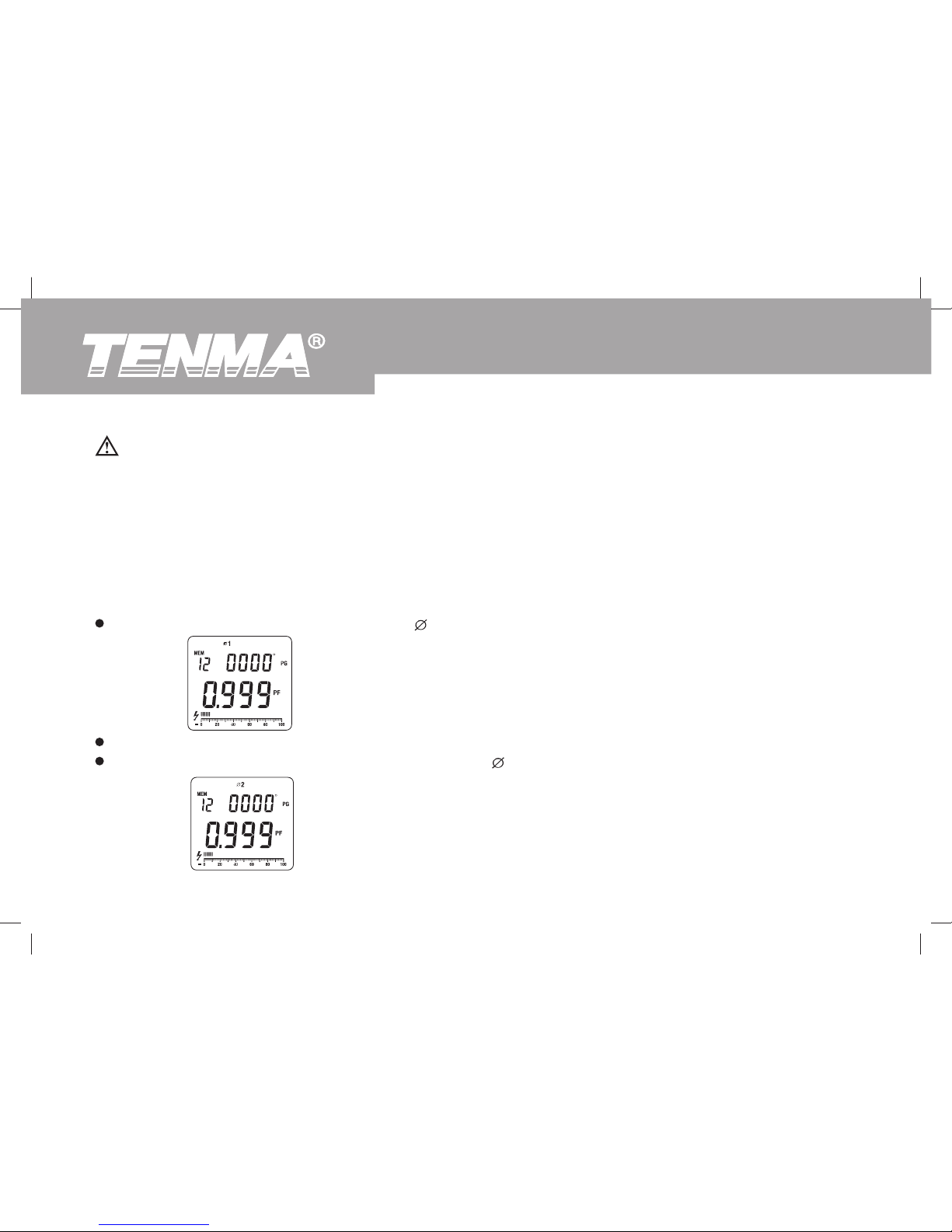
The double display shows the first phase value of power factor PF and phase angle PG.
To test for Power factor (main display) + Phase angle (secondary display), connect the Meter as follows:
1. Press the MENU to select Power factor (main display) + Phase angle (secondary display) range.
2. Press the lever to open the transformer jaw, and clamp them to the corrresponding phase of tested conductor. If
user needs to mesaure any phase of the 3 phase, then clamp them to that phase’s conductor.
3. The connecting method of 3 phases 4 wires, 3 phases 3 wires or single phase 2 wires, see figure 6, 7 and 8
4. When measuring 3 phase 4 wires: (see figure 20, 21, 22)
Press SELECT to choose the first phase 1, see figure 20.
To avoid damage to the Meter or personal injury, do not exceed AC voltages of 600V rms and AC
Current of 1000A rms.
Warning
E. Power Factor (main display) + Phase Angle (secondary display) Measurement
Figure 20
Then press SELECT again to choose the second phase 2,see figure 21.
Figure 21
Page 32
72-9490: OPERATING MANUAL
31
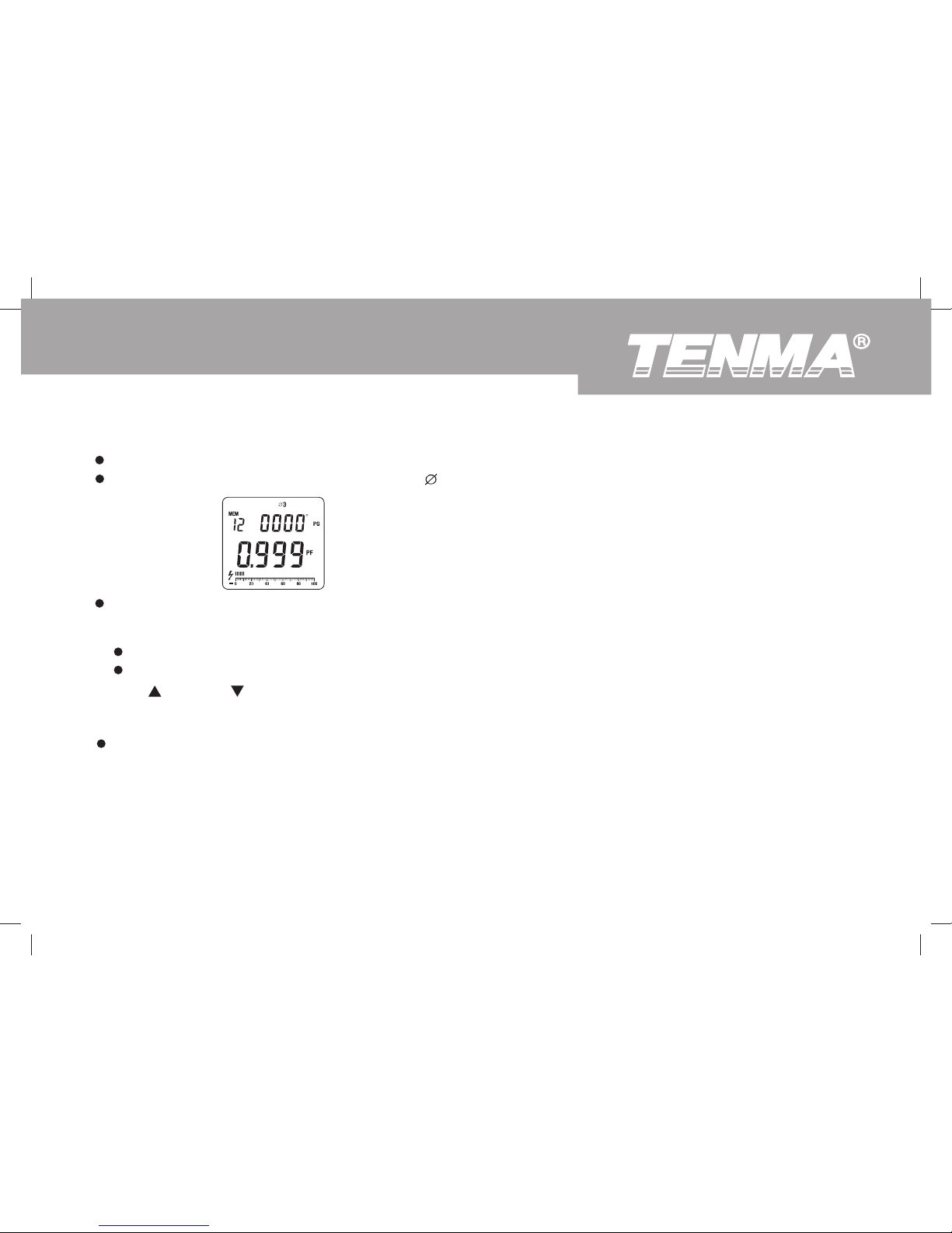
The double display shows the third phase value of power factor PF and phase angle PG.
Figure 22
The double display shows the second phase value of power factor PF and phase angle PG.
Press SELECT again to choose the third phase 3, see figure 22.
5. When measuring 3 phase 3 wires:
The first phase and second phase operating method is same as three phase 4 wires.
Jump over the third phase measurement.
6. MAX/ and MIN/ are not valid when measuring power factor.
Note
When testing has been completed, disconnect the connection between the testing leads and the circuit under test
and remove testing leads from the input terminals.
Page 33
To avoid damage to the Meter or personal injury, do not exceed AC voltages of 600V rms and AC
Current of 1000A rms.
32
72-9490: OPERATING MANUAL
To test for Active Energy (main display) + Time (secondary display), connect the Meter as follows:
1. Press the MENU to select Power factor (main display) + Phase angle (secondary display) range.
2. Press the lever to open the transformer jaw, and clamp them to the corrresponding phase of tested conductor. If
user needs to mesaure any phase of the 3 phase, then clamp them to that phase’s conductor.
3. The connecting method of 3 phase 4 wires, 3 phases 3 wires or single phase 2 wires, see figure 6, 7 and 8
4. Press SELECT to choose one of the three phases ( 1, 2, 3), see figure 23.
F. Active Energy (main display) + Time (secondary display) Measurement
Warning
Figure 23
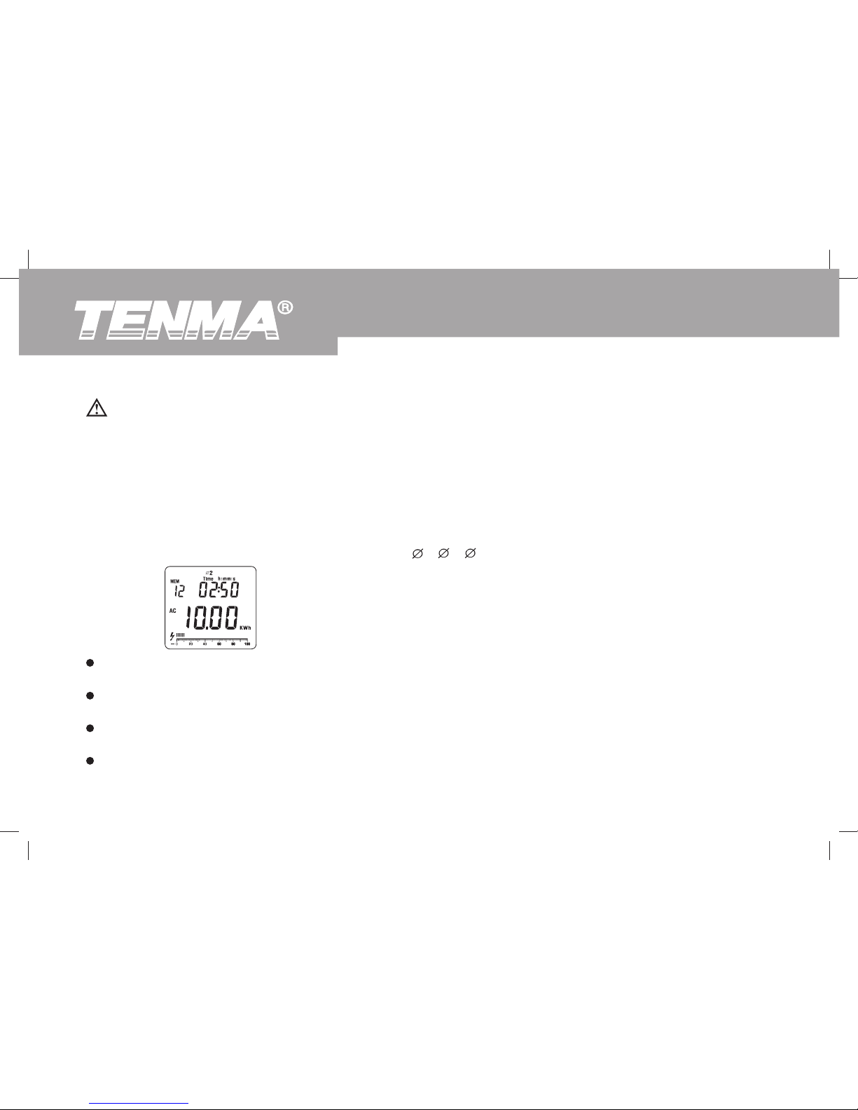
The double display shows the value of tested object’s active engergy kWh value and the measuring time of the
corresponding phase.
The measuring reading gets increasing along with the time increases. Press HOLD to read a particular time
kWh value. Then the reading and time are locked, but still continuous accumulate measuring time.
After read the data, press HOLD again to continous measurement. kWh value continous accumulate and the
measuring time jumps to the present measuring time.
When the measuring time is over 24 hours or the Meter is switched to other measuring ranges, active energy
measuring will stop.
Page 34

72-9490: OPERATING MANUAL
33
True RMS Measurement and Average Value Measurement
The True RMS measurement method can measure accurately the effective value of non-sine wave input signal.
Average value measurement method can measure the mean value of one sine wave input signal, and then displays
it as RMS value
Note
When there is no input signal, it cannot carry out active energy measurement.
When there is input signal, the maximum waiting time is approximately 10s before timing.
When testing has been completed, disconnect the connection between the testing leads and the circuit under test
and remove testing leads from the input terminals.
5. MAX/ and MIN/ are not valid when measuring active energy.
6. Press CLEAR to reset the time.
The maximum reading of acitve energy is 9999kWh. OL will be displayed when the reading is over than that.
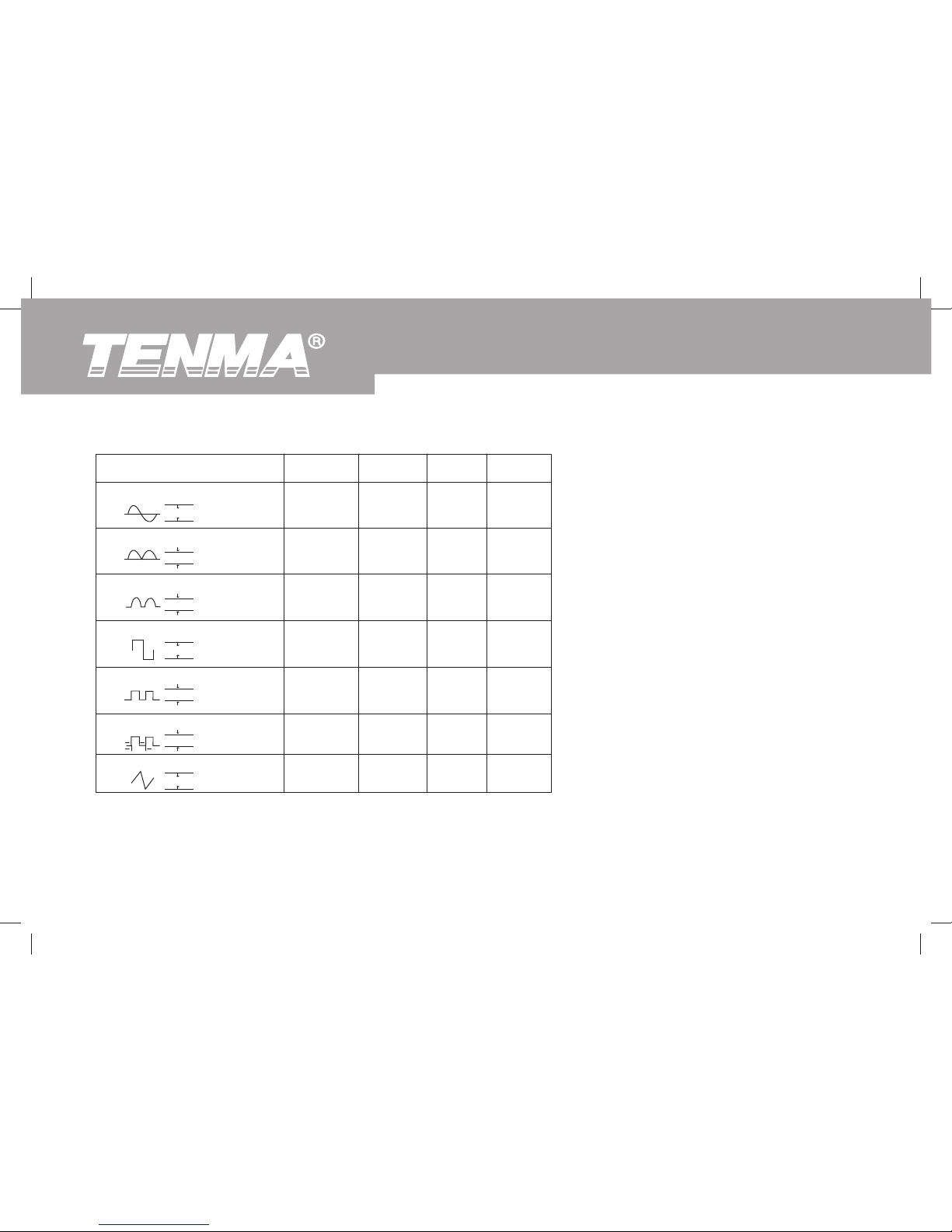
When the input waveform has distortion, measuring tolerance will be included. The total tolerance depends on the
total distortion. Below table 1 shows the waveform coefficient and the relationship and the requested changing factor
of sine wave, square wave, peak wave of triangle wave, RMS value and average value.
Page 35
34
72-9490: OPERATING MANUAL
Input Waveform PK-PK 0-PK RMS AVG
Sine waveform
PK
0
PK-PK
complete sine waveform
PK
0
PK-PK
Half wine waveform
PK
0
PK-PK
square waveform
PK
0
PK-PK
commutate square waveform
PK
0
PK-PK
X
0
PK-PK
Y
Rectangle pulse waveform D=X/Y
triangle waveform
PK
0
PK-PK
2.828
1.414
2.828
1.800
1.800
0.9/D
3.600
1.414
1.414
2.828
0.900
1.800
0.9/ D
1.800
1.000
1.000
1.414
0.900
1.272
0.9/D
1.038
0.900
0.900
0.900
0.900
0.900
0.9/D
0.900
Page 36
72-9490: OPERATING MANUAL
35
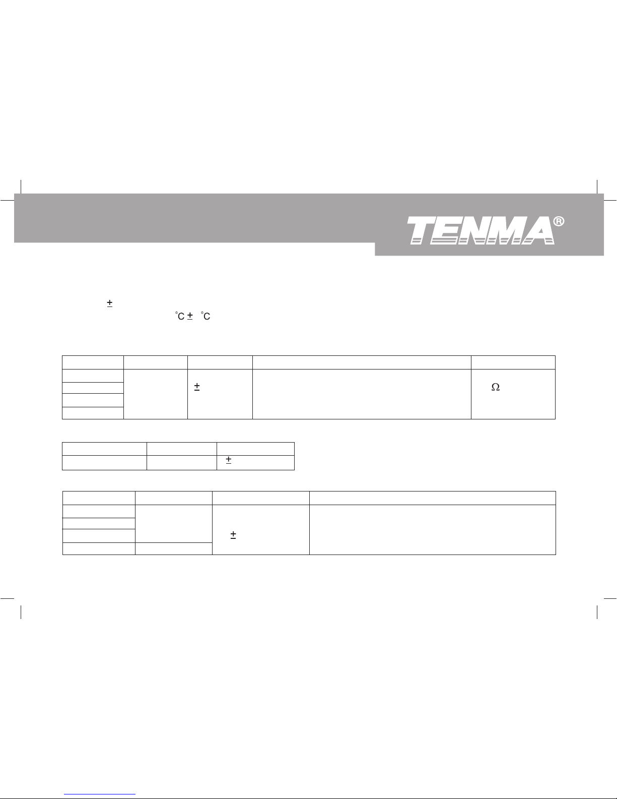
Storage Temperature: -10 ~60
Dimensions: 303mm x 112mm x 39mm
Weight: Approximate 601g
Specifications
A. General Specifications
Maximum Voltage between any Terminal and grounding: Refer to different range input protection voltage.
Display: Multi LCD displays, Maximum display 9999.
Ranges: Auto
Overloading: Display OL.
Battery Deficiency: Display
.
Data Holding: Display
Data Logging: Maximum 99, Single or Continuous records
Data Recall
Maximum and Minimum value display: Voltage, Current, Active Power and Apparent Power ranges
Display Backlight: White color
Computer connection: USB
Calibration Feature
Sleep Mode: To preserve battery life, the Meter automatically turns off if you do not turn press any button for
approximately 15 minutes, except at active energy range.
Sampling: 3 times per second.
Max. Jaw Size: 55mm diameter.
Analog Bar Graph
Power: 4 x 1.5V battery (LR6)
Page 37
36
72-9490: OPERATING MANUAL
B. Environmental Requirements
The Meter is suitable for indoor use.
Altitude: Operating: 2000m
Storage: 10000m
Temperature and humidity:
Operating:
0
~ 30 ( 85%R.H)
30
~ 40 ( 75%R.H)
40
~ 50 ( 45%R.H)
Storage:
-10
~ +60 ( 85%R.H)
Safety/ Compliances: IEC 61010 CAT. III 600V, CAT. IV 300V overvoltage and double insulation standard,
pollution degree 2.
Certification:
Page 38
72-9490: OPERATING MANUAL
37
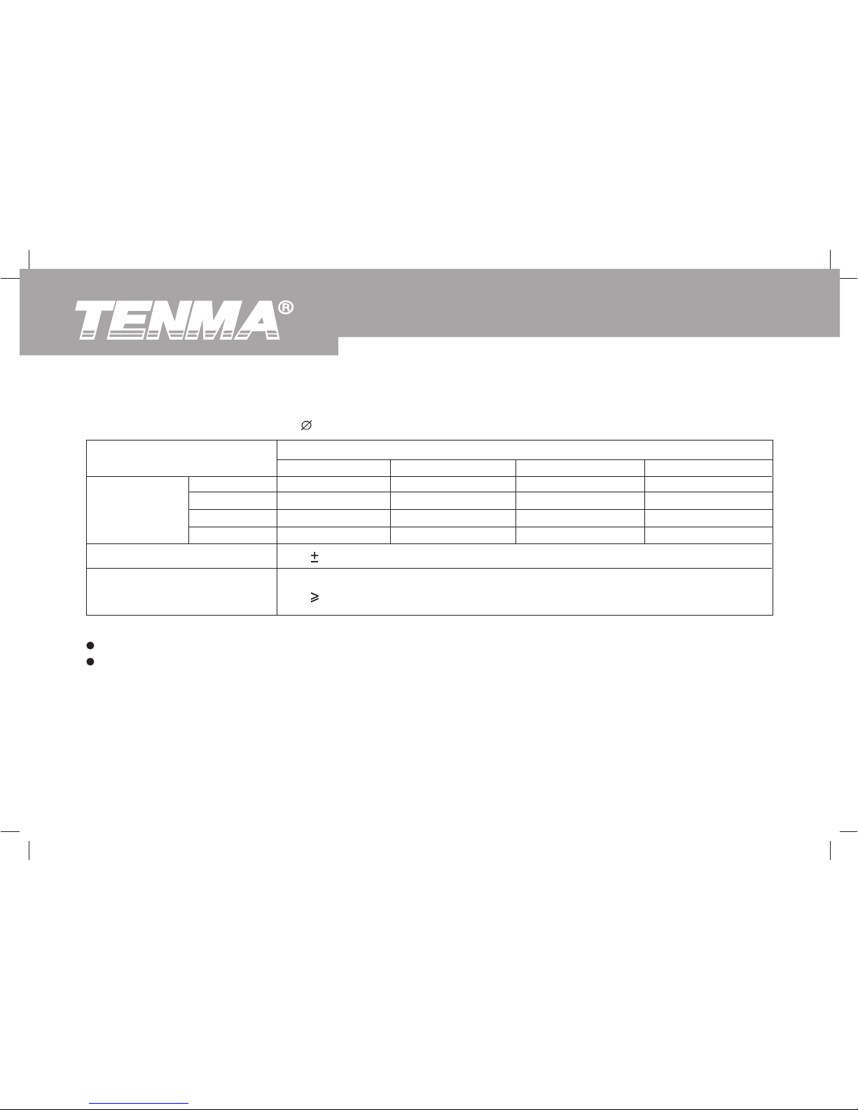
C. AC Current (True RMS)
Range
40A
100A
400A
1000A
Resolution
0.1A
1A
Accuracy
(2%+5)
Allowable Maximum overload protection current
1000A RMS
Accurate Specifications
Accuracy: (a% reading + b digits), guaranteed for 1 year.
Operating temperature: 23
5
Operating humidity: 45~75%R.H
A. AC Voltage (True RMS)
Range
15V
100V
300V
600V
Resolution
0.1V
Accuracy
(1.2%+5)
Allowable Maximum overload protection voltage
600 RMS
Input Impedance
10M
B. Frequency
Range
20Hz~500Hz
Resolution
1Hz
Accuracy
(0.5%+5)
Page 39
38
72-9490: OPERATING MANUAL
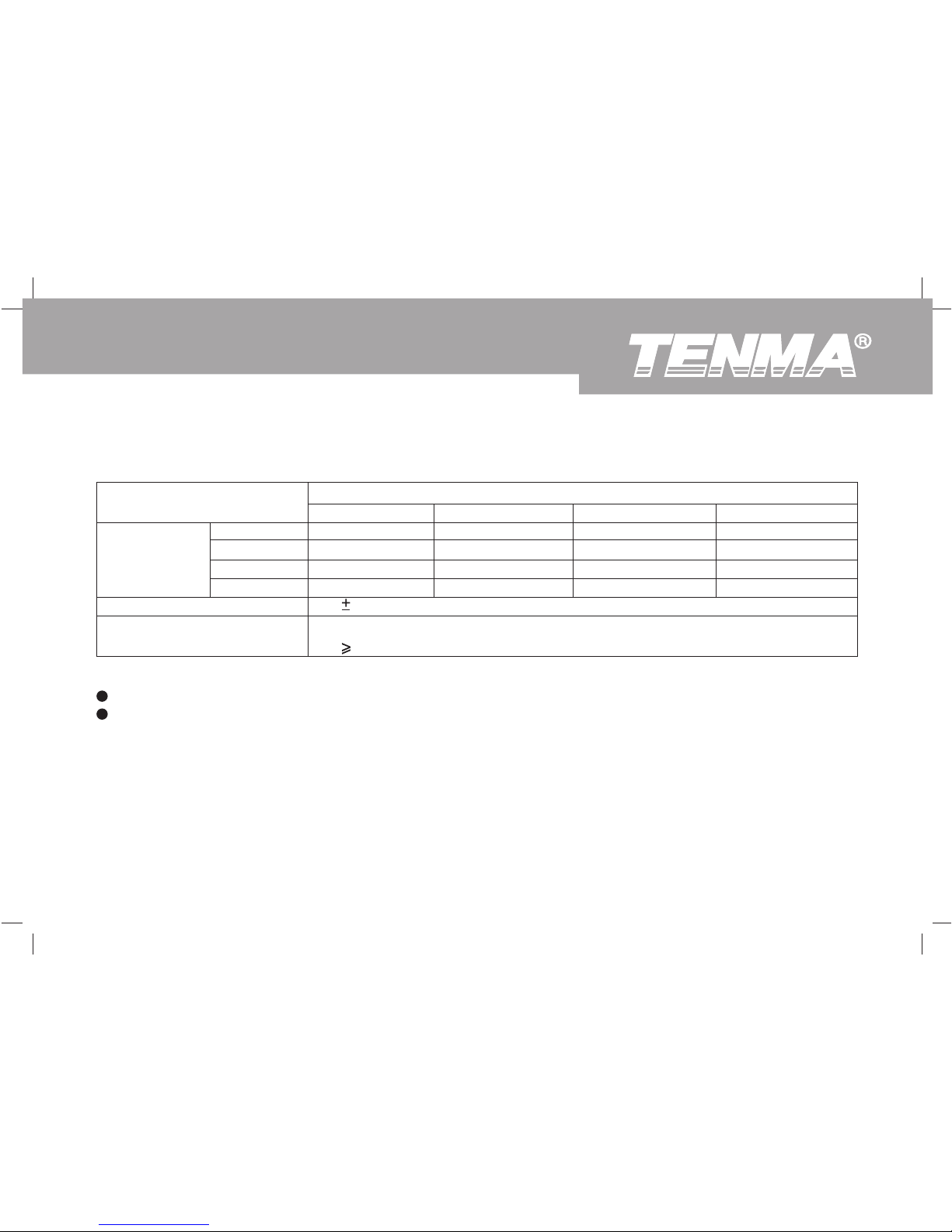
D. Active Power ( W=V x A x COS )
Current / Voltage
Current
Range
40A
100A
400A
1000A
15V
0.60kW
1.50kW
6.00kW
15.00kW
100V
4.00kW
10.00kW
40.00kW
100.0kW
300V
12.00kW
30.00kW
120.0kW
300.0kW
600V
24.00kW
60.00kW
240.0kW
600.0kW
Voltages Range
Accuracy
Resolution
(3%+5)
<1000kW: 0.01kW
100kW: 0.1kW
Remarks:
Allowable maximum overload protection voltage: 600V RMS
Allowable maximum overload protection current: 1000A RMS
Page 40
72-9490: OPERATING MANUAL
39
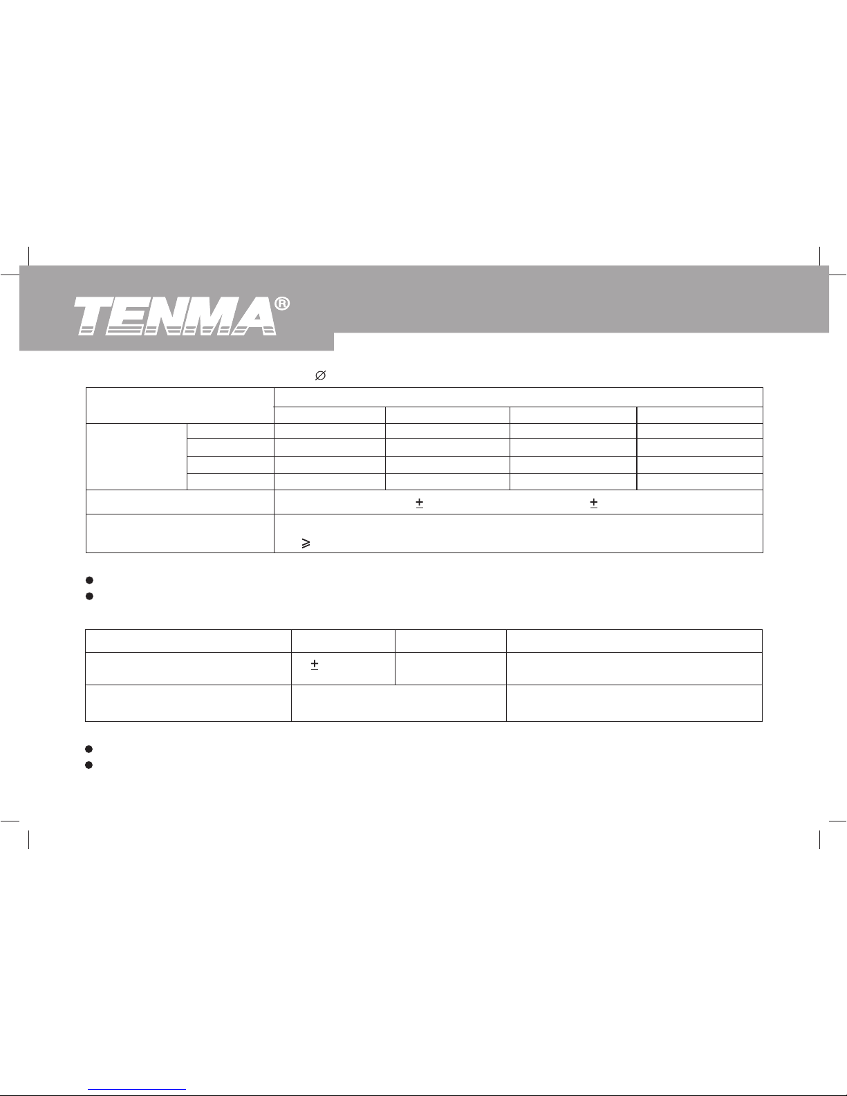
E. Apparent Power (VA = V x A)
Current / Voltage
Current
Range
40A
100A
400A
1000A
15V
0.60kVA
1.50kVA
6.00kVA
15.00kVA
100V
4.00kVA
10.00kVA
40.00kVA
100.0kVA
300V
12.00kVA
30.00kVA
120.0kVA
300.0kVA
600V
24.00kVA
60.00kVA
240.0kVA
600.0kVA
Voltages Range
Accuracy
Resolution
(3%+5)
<1000kVA: 0.01kVA
100kVA: 0.1kVA
Remarks:
Allowable maximum overload protection voltage: 600V RMS
Allowable maximum overload protection current: 1000A RMS
Page 41
40
72-9490: OPERATING MANUAL
G. Power Factor (PF = W / VA)
Range
0.3~1
(capacitive or inductive)
0.3~1
(capacitive or inductive)
Accuracy
0.022
Resolution
0.001
Measuring Condition
The minimum measuring current 10A
The minimum measuring voltage 45V
Measuring current less than 10A OR
Measuring voltage less than 45V
For reference only
Remarks:
Allowable maximum overload protection voltage: 600V RMS
Allowable maximum overload protection current: 1000A RMS
F. Reactive Power (Var = V x A x SIN
)
Current / Voltage
Current
Range
40A
100A
400A
1000A
15V
0.60kVar
1.50kVar
6.00kVar
15.00kVar
100V
4.00kVar
10.00kVar
40.00kVar
100.0kVar
300V
12.00kVar
30.00kVar
120.0kVar
300.0kVar
600V
24.00kVar
60.00kVar
240.0kVar
600.0kVar
Voltages Range
Accuracy
Resolution
15V/1000A Range:
(4%+20) Other Ranges: (4%+5)
<1000kVar: 0.01kVar
100kVar: 0.1kVar
Remarks:
Allowable maximum overload protection voltage: 600V RMS
Allowable maximum overload protection current: 1000A RMS
Page 42
72-9490: OPERATING MANUAL
41
H. Phase Angle (PG=acos (PF))
Range
0° ~360°
0° ~360°
Accuracy
1°
Resolution
1°
Measuring Condition
The minimum measuring current 10A
The minimum measuring voltage 45V
Measuring current less than 10A OR
Measuring voltage less than 45V
For reference only
Remarks:
Allowable maximum overload protection voltage: 600V RMS
Allowable maximum overload protection current: 1000A RMS
Remarks:
Allowable maximum overload protection voltage: 600V RMS
Allowable maximum overload protection current: 1000A RMS
I. Active Energy (kWh)
Range
1~9999kWh
Accuracy
(3%+2)
Resolution
0.001kWh
Page 43
42
72-9490: OPERATING MANUAL
To clean the terminals, wipe with cotton or lint free cloth and mild detergent. Dirt or moisture on the terminals may
affect readings.
Remove the battery when not in use for an extended period of time.
MAINTENANCE
This section provides basic maintenance information including battery replacement instruction.
Do not attempt to repair or service your Meter unless you are qualified to do so and have the relevant calibration,
performance test, and service information.
To avoid electrical shock or damage to the Meter, do not get water inside the case.
Warning
A. General Service
Periodically wipe the case with a damp cloth and mild detergent. Do not use abrasives or solvents.
Turn the Meter off when not in use.
Do not store the Meter in places of high temperature, humidity, explosive/flammable environments, or in a strong
magnetic field.
Page 44
72-9490: OPERATING MANUAL
43
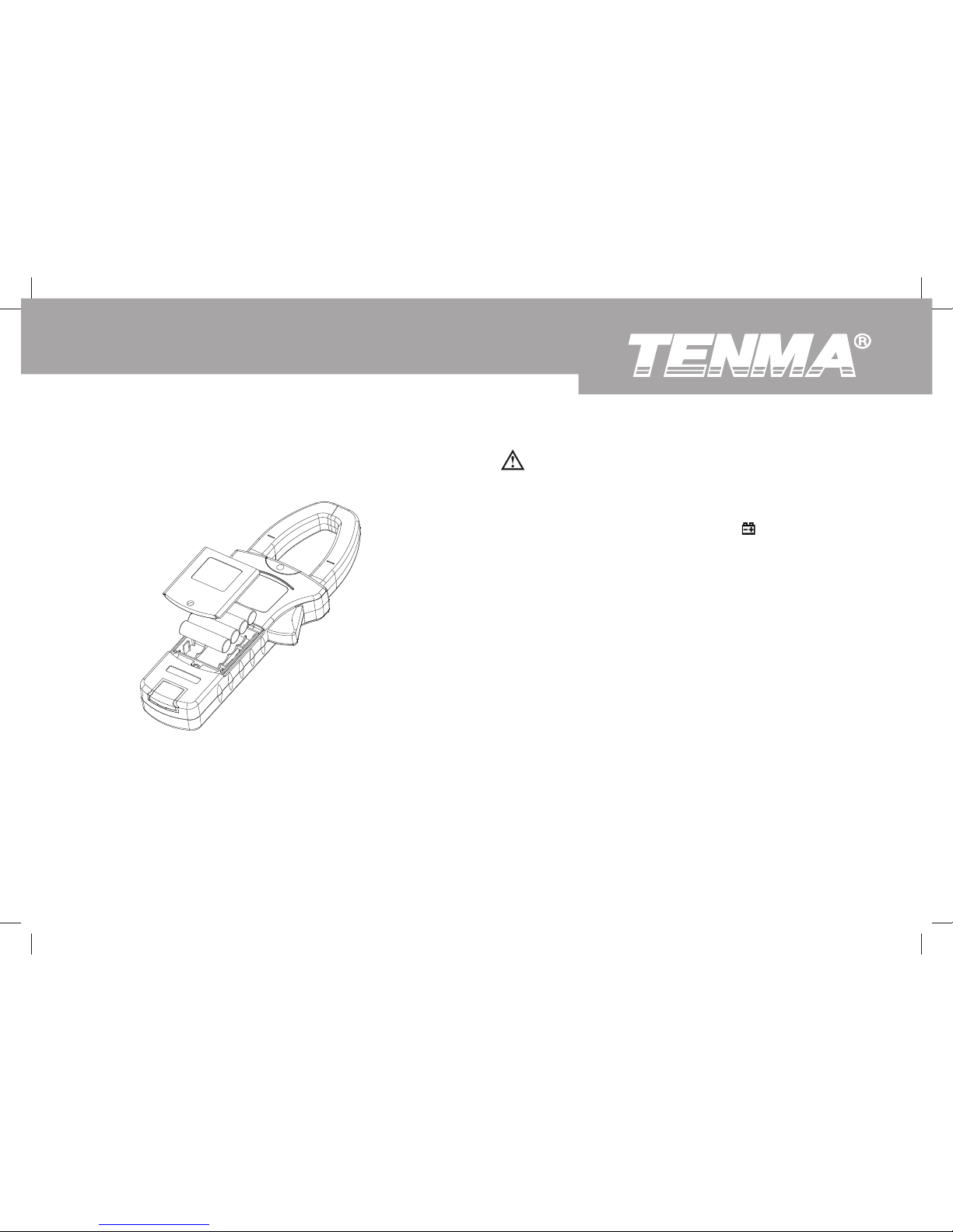
Figure 24
B. Replacing the Battery (see figure 24)
To avoid false readings, which could lead to possible
electric shock or personal injury, replace the battery
as soon as the battery indicator “
” appears.
Make sure the transformer jaw and the tests leads
are disconnected from the circuit being tested before
opening the case bottom.
Warning
To replace the battery:
1.
2.
3.
4.
5.
Press POWER to turn the Meter off and remove all
the connections from the input terminals.
Turn the Meter’s front case face down.
Remove the screw from the battery door, and
separate the battery door from the case bottom.
Take out the old battery and replace with 4 x 1.5V
batteries (LR6).
Rejoin the case bottom and the battery door, and
reinstall the screw.
Page 45

44
72-9490: OPERATING MANUAL
C
This operating manual is subject to change without notice
Copyright 2012
All rights reserved.
Manufacturer:
Tenma Test Equipment
405 S. Pioneer Blvd.
Springboro, OH 45066
http://www.tenma.com
 Loading...