

Page 1
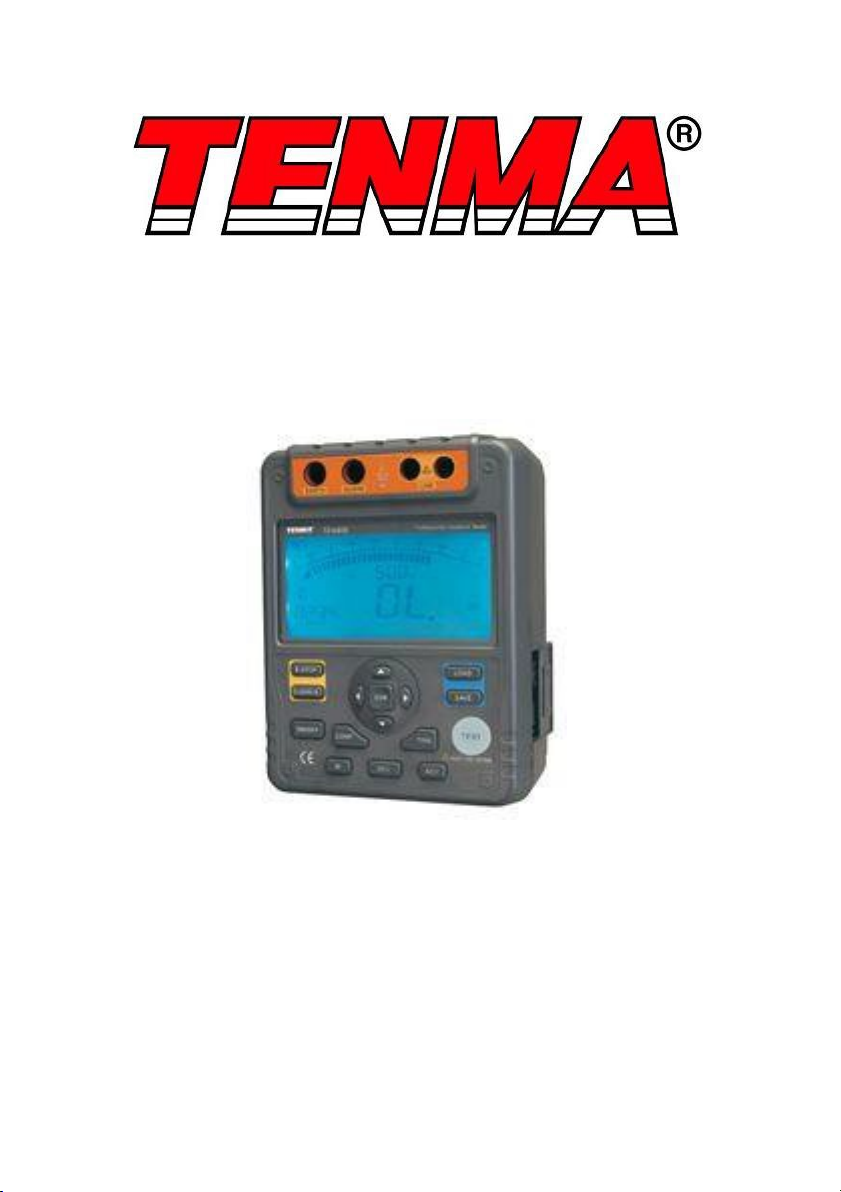
2500V Digital Insulation Resistance Tester
Model: 72-9405
1
Page 2

SAFETY INSTRUCTIONS:
This meter complies with IEC61010 safety measurement requirement. Pollution
this instrument.
Do not apply more than 600V to the instrument
When carrying out insulation measurement, do not contact the circuit under
same electrical specification as the original parts.
•
• •
•
•
•
•
2
degree 2, CAT III 600V.
Please read the following safety information carefully before using or servicing
•
•
Do not use the instrument around explosive gas, vapour, or
•
dust Do not use the instrument in a wet environment
•
When using test leads, keep fingers away from lead contacts and behind
finger guards on the leads
When performing insulation resistance tests, disconnect and discharge all
•
power from the circuit to be measured
Do not short circuit testing leads during high voltage output or test
insulation resistance after high voltage output.
Do not measure over 10 seconds when:
•
Measuring resistance <2MΩ with use of 500V
Measuring resistance <5MΩ with use of 1000V
Measuring resistance <8MΩ with use of 1500V
Measuring resistance <10MΩ with use of 2500V
At any output voltage, when tested resistance is less than 10MΩ,
continuous testing time cannot exceed 10 seconds.
Operating the meter must be done very carefully as it outputs dangerous
voltages during measurement. Test object must be firmly clamped, and
hand must be away from measurement clips before pressing TEST button
to output high voltage.
Be careful when working above 33Vrms, 46.7V AC rms or 70V DC, such
voltages pose shock hazard
Discharge all loading of circuit under test after measuring high voltage
•
Place test leads in proper input terminals, make sure all test leads are
•
firmly connected to the meter’s input terminals
When performing resistance tests, remove all power from the circuit to be
measured and discharge all remaining power
Do not use the instrument with any parts or cover removed
•
test.
Do not use the instrument if it is damaged or if metal parts are
•
exposed. Check to make sure no cracks or missing plastic parts
before using the instrument
Do not change battery in wet environments
•
Make sure the meter is turn off when opening battery compartment.
•
When servicing the meter, use only test leads and power adaptor with the
•
Page 3

Do not attempt to repair or service the meter unless you are qualified to do
information
WHAT’S INCLUDED
Test Meter
plug to alligator clip
Software
3
•
Take the battery out from the meter if it is not used for a long time
•
Do not use or store meter in high temperature, humid, inflammable, and
strong magnetic field environments
•
Soft cloth and mild detergent should be used to clean the surf ace of the
meter when servicing. No abrasive and solvent should be used on the
meter
•
Make sure the meter is dry before storing away
•
so and have the relevant calibration, performance test, and service
•
3 x test leads (red, black & green) –
•
Instruction Manual
•
Tool Box
•
•
USB interface cable
•
Page 4
MEASUREMENT OPERATIONS
This section explains how to make measurements.
Press and hold ON/OFF to turn on, and press it again to turn off the meter.
After turning on the meter, it defaults at 500V range and continuous
measurement of insulation resistance.
Measuring Voltage
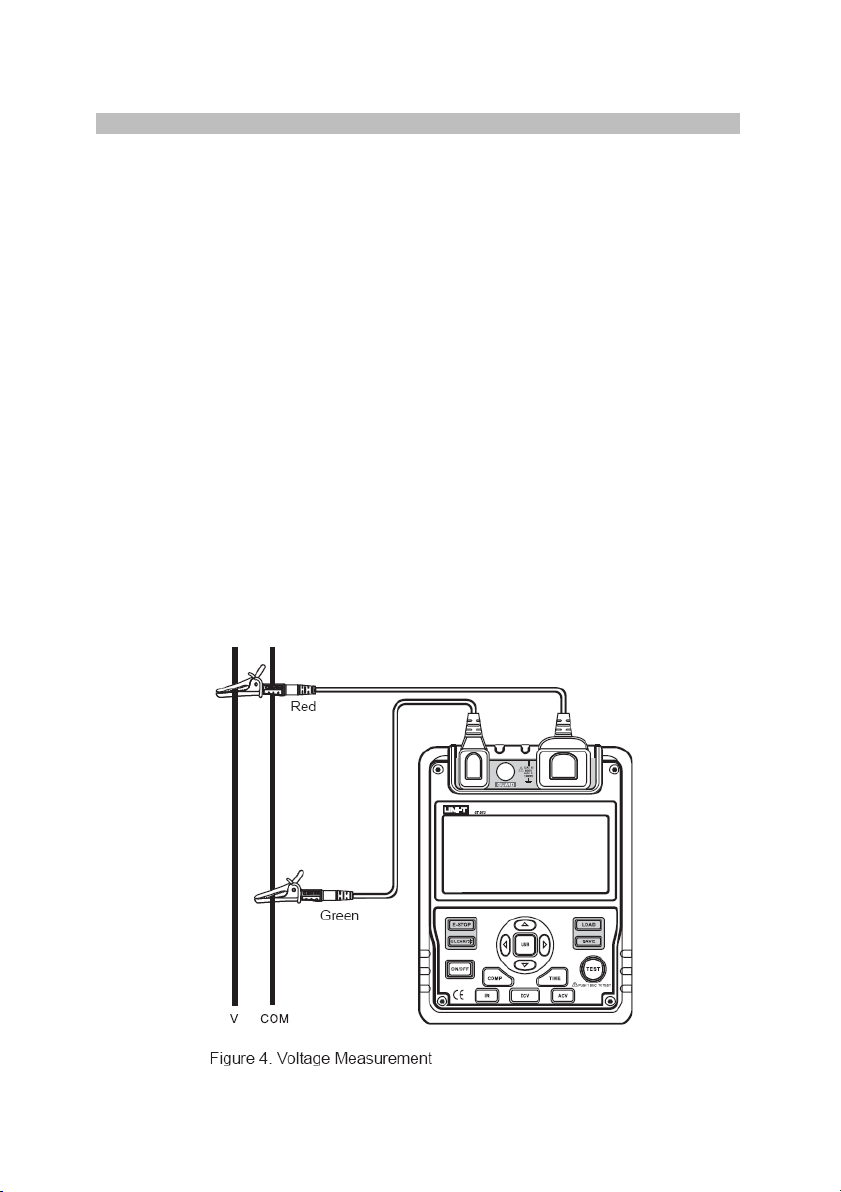
To measure voltage, set up the meter as in Figure 4 and perform the steps
Press DC V or AC V button to select DC or AC voltage measurement.
Insert the red and green test leads into EARTH and two LINE terminals.
When measuring DC voltage, if negative voltage is present on the red test
measure voltage higher than 600V or 600V rms, although the reading may
Special care should be taken when measuring high voltage.
• •
Note: When voltage measurement has been completed, disconnect the test
he circuit under test and remove them away from the meter input
4
•
•
below,
•
•
•
lead, “-” will show on the display.
To avoid harm to you or damage to the meter, please do not attempt to
be obtained.
leads fr om t
terminals.
Page 5
Measuring Insulation Resistance
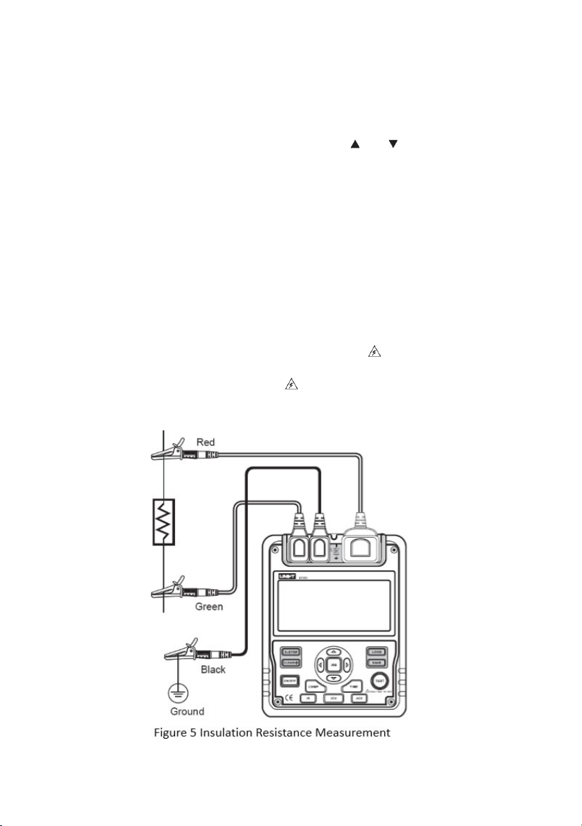
To measure insulation resistance, set up the meter as Figure 5 and perform the
steps below.
Press IR button to select insulation resistance measurement.
When there is no testing voltage output, press
1000V, 2500V or 5000V range.
and
to select 500V,
When performing insulation resistance tests, discharge all the power of the
Insert the red test lead into two LINE terminals, the black one into GUARD
below,
Continuous Measurement
• Press TIME button to select continuous mode. No timer icon shows on the
Press and hold TEST button for 1s to begin and output insulation
resistance testing voltage. TEST button lights up,
blinks every 0.5s.
Press TEST button to turn off the voltage output, when the measurement is
completed. TEST button lights off,
disappears. The LCD shows the
current insulation resistance measurement value.
5
•
•
•
circuit to be measured, and keep it away from power circuit.
•
and the green one into EARTH.
•
Connect the red and green alligator clips to the circuit to be measured.
Negative voltage outputs from LINE terminal.
Choose one of the insulation resistance measurement modes shown as
•
LCD.
•
•
Page 6
Timed Measurement
Press TIME button to select the timed mode, the LCD displays TIME 1 and
Press
and
buttons to set the time (00:10~15:00). Within 1 minute, the
time increment or decrement by every 5s. Afterward, the time increment or
Then press and hold TEST button for 2s to carry out timed measurement.
TIME 1 and
display and blink on the LCD every 0.5s.
•
When the set time is reached, the test voltage output will be turned off, and
insulation resistance reading.
Polarization Index (PI) Measurement
Press TIME button to select the timed mode, the LCD displays TIME 1 and
Press
and
buttons to set the time (00:10~15:00). Within 1 minute, the
time increment or decrement by every 5s. Afterward, the time increment or
Press TIME button again. TIME 2, PI and
symbol appear on the LCD.
Press
and
buttons to set the time (00:15~15:30). Within 1 minute, the
time increment or decrement by every 10s. Afterward, the time increment
Then press and hold TEST button for 2s to carry out the measurement.
TIME 1 and
display and blink on the LCD every 0.5s before TIME 1 set
time is reached.
TIME 2 and
display and blink on the LCD every 0.5s before TIME 2 set
time is reached.
•
When the set time of TIME 1 & 2 is reached, the test voltage output will be
displays the polarization index reading.
•
Press
to step through the polarization index, TIME 2 and TIME 1
insulation resistance readings.
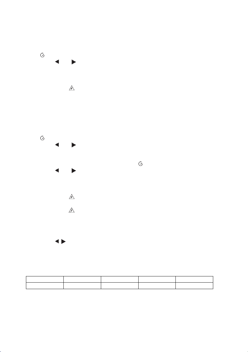
Calculation tips:
PI=3-minute~10- minute resistance / 30-second~1-minute resistance
6
PI
4 or more
4~2
2.0~1.0
1.0 or less
Standard
Best
Good
Warning
Bad
•
symbol.
•
decrement by every 30s.
•
the measurement will be automatically stopped. The LCD displays the
•
symbol.
•
decrement by every 30s.
•
•
or decrement by every 30s.
•
•
•
turned off, and the measurement will be automatic ally stop p ed. T he LCD
Page 7
Compare Function
Press COMP button to select compare feature. COMP displays on the
Press
and
buttons to set the compare value.
You can choose the compare value from 10MΩ, 20MΩ, 30MΩ, 40MΩ,
7
•
LCD.
•
•
50MΩ, 60MΩ, 70MΩ, 80MΩ, 90MΩ, 100MΩ, 200MΩ, 300MΩ, 400MΩ,
500MΩ, 600MΩ, 700MΩ, 800MΩ, 900MΩ, 1GΩ, 2GΩ, 3GΩ, 4GΩ, 5GΩ,
6GΩ, 7GΩ, 8GΩ, 9GΩ, 10GΩ, 20GΩ, 330GΩ, 40GΩ, 50GΩ, 60GΩ, 70GΩ,
80GΩ, 90GΩ, 100GΩ.
•
Press and hold TEST button for 2 secs to carry out the measurement.
•
NG will display if the insulation resistance value is smaller than the
compare value. Otherwise, GOOD will display.
 Loading...