


Illustration
Thank you for purchasing our product. Please read this manual to be familiar with the product.
Note: this manual is written to provide all the relevant information for the series of models. Due to the different signal configurations, the actual product configuration may differ from the instructions.

Important Safety Precautions
(Instructions for Fire, Electric Shock or Personal Injury) Note- The following basic precautions are provided for the use of the electrical appliance:
1.You should read Safety precautions carefully before using the products.
2.This product shall be grounded. In case of any fault, the current will flow to the earth through the grounding resistance so as to reduce electric shock. The power cord and plug of product shall be properly grounded. The plug shall be inserted into a proper socket, which shall be installed and grounded in accordance with local regulations.
Warning- Improper grounding can cause electric shock.
If you have any question on proper grounding of product, ask a qualified electrician or service personnel to check. Please do not try to change the power plug of product. If it is not fit for the socket, ask a qualified electrician to install an appropriate power socket.
3.To reduce injury risk, closely supervise kids when using the appliance near them.
4.Do not use the machine in a very humid place, for example, near a bathtub, wash basin, kitchen sink, and humid basement or near a swimming pool or lake.
5.The product shall be installed in a well-ventilated place.
6.The product shall be kept away from heat sources such as electric heaters, electric blankets or other heat-generating products.
7.The type of power supply for the product must conform to the type indicated on the appliance
8.Take care not to allow any foreign substance or liquid to fall into the appliance.
9.In case of the following, turn to qualified service personnel for repair:
A Power cord or plug is damaged.
B Some foreign substance or liquid has fallen into the machine.
C The product is exposed to rain.
D The product is not working properly or significant changes occur in the performance.
E The product has been broken or its appearance is damaged.
10.In case of any situation not mentioned in the User Maintenance Guide, do not attempt to repair by yourself. Turn to qualified service personnel for repair.
11.Warning - Do not allow heavy articles to stay on, or anybody step on, pull or twist any power cord. Do not abuse the cord. A damaged power cord may cause fire or harm to human.

Table of Content |
|
Illustration......................................................................................................................................... |
1 |
Important Safety Precautions........................................................................................................... |
2 |
Table of Content ............................................................................................................................... |
3 |
I. Device Architecture .................................................................................................................. |
4 |
II. Software Instructons .................................................................................................................... |
6 |
2.1 Menu Bar and Toolbar ........................................................................................................ |
7 |
2.1.1 File ........................................................................................................................... |
7 |
2.1.2 Local Settings ........................................................................................................... |
7 |
2.1.3 Device Settings......................................................................................................... |
8 |
1 User Manager ..................................................................................................... |
8 |
2 Scene Manager ................................................................................................... |
9 |
3 Network Settings .............................................................................................. |
10 |
4 Serial Port Settings............................................................................................ |
10 |
5 Voice tracking ................................................................................................... |
11 |
6 GPIO.................................................................................................................. |
13 |
7 Device Update .................................................................................................. |
28 |
2.2 Audio input module.......................................................................................................... |
28 |
2.2.1Input source............................................................................................................ |
30 |
2.2.2Exp/Gate................................................................................................................. |
31 |
2.2.3EQ ........................................................................................................................... |
32 |
2.2.4Compress................................................................................................................ |
33 |
2.2.5AGC ......................................................................................................................... |
34 |
2.3 Scene Control and GPIO.................................................................................................... |
35 |
2.4Auto Mixer......................................................................................................................... |
35 |
2.5Ducker................................................................................................................................ |
37 |
2.6 SPL (Sound Pressure Level)............................................................................................... |
38 |
2.7Telephone control.............................................................................................................. |
39 |
2.8 AFC.................................................................................................................................... |
41 |
2.9AEC..................................................................................................................................... |
42 |
2.10 Extendeder Mixer ........................................................................................................... |
43 |
2.11 Cobranet Mixer............................................................................................................... |
45 |
2.11.1 Cobrane Rreceiver Setting ................................................................................... |
45 |
2.11.2 Cobranet Ooutput................................................................................................ |
45 |
2.11.3 Cobranet Transmitter Setting .............................................................................. |
46 |
2.12 Audio output module ..................................................................................................... |
47 |
2.12.1From ..................................................................................................................... |
48 |
2.12.2Speaker Manager.................................................................................................. |
49 |
2.12.3 Limiter.................................................................................................................. |
50 |
2.12.4 Output setting...................................................................................................... |
51 |
.FAQ ............................................................................................................................................ |
52 |

I.Device Architecture
Figure 1
The front panel of device is shown in Figure 1
-Power indicator: after the power supply is switched on, light indicates power status.
-Status indicator: the system will run normally if the indicator is flickering and the indicator will be ON for a long time during upgrading.
-Telephone indicator: the indicator will be ON when enabling the telephone module. Otherwise, the indicator is OFF. TC series only.
-Input signal indicator: Illuminates when there is an input signal present. The number of indicators is equal to total number of input channels of on the device.
-Output signal indicator: Illuminates if there is an output signal present, the number of indicators is equal to total number of output channels on the device.
The rear panel of device is shown in Figure 1:
-AVC220V: power plug, supporting AC 100V~240V power supply, 50~60Hz, power soft switch;
-M-LAN: network interface, connect PC, on-line editing and command receiving and sending control;
-RC-LINK: external control panel interface, to connect RC panel via the network cable;
-TEL/OUT,TEL/IN telephone access module;
-RS232: communication interface, to connect the external central control equipment / support camera tracking;
-GPIO: order transfer. For the specific connection mode, see GPIO setting in 2.1.3.6;
-RS485: support camera tracking;

-4---A 485+
-5----B 485-
-8---- grounding
-485 wire on the video camera is normally blue and brown. Then the brown is +, connecting to A on the equipment 485; and the blue is -, connecting to B on the equipment 485;
Figure 2
-INPUT: Analog audio MIC \ LINE input interface;
-OUTPUT: Analog audio output interface;
-RSET: System stem reset button;
-LANK-RX/LANK-TX: Connection (MINI T-LAN interface);
-SECONDARY/PRIMARY: Cobranet interface.
II. Software Instructons
Installation of software: the software supports XP, win7, and vista operating systems. Before installing the software, please make sure the computer net framework3.5 installed. Then, in the IP address of PC, there is at least an address fallen into the same network segment as the device IP address (the default IP address ex factory is 192.168.10.10). Otherwise, the device can be queried only and cannot be normally connected. If the PC is not provided with IP address fallen into the same network segment as the device, please refer to the correct setting in the notes for using the device for the first time in FAQ hereinafter.
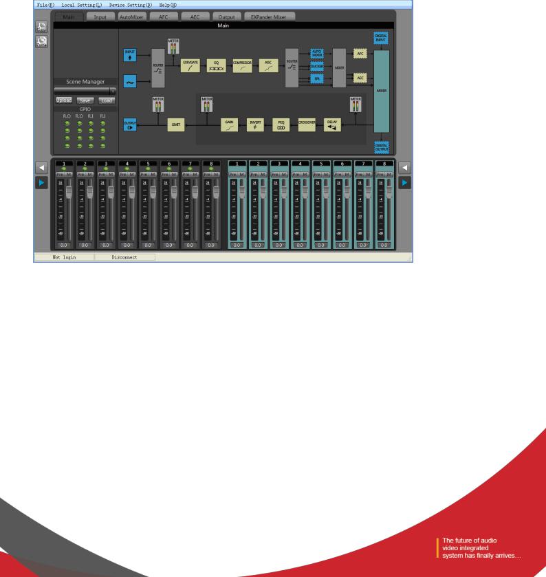
After the PC software is properly installed, the starting interface is as shown in Figure 3:
Figure 3
-Menu bar and tool bar: the menu bar contains various function menus of the software, and the tool bar displays function menus in common use.
-Copy / paste: parameter copy between channels or parameter copy between same functional module. The interface choice box is red, indicating that the module can conduct copy / paste operations.
-Channel parameter control area: indicating parameters of various functional modules of each channel. The choice box is red, indicating that the module can conduct copy / paste operations.
-Input / output channel control area: to display the electrical level and gain of each channel, select any channel, and the corresponding specific parameters will be displayed in Module 3; part of the hidden channel can be switched
with ;When the channel choice box is red, the channel can conduct copy / paste operations. When the channel choice box is blue, the parameters of the current channel are displayed in Module (3) .
-Status bar: to display the current DSP occupancy factor, login status and connection status of the connecting machine.
2.1 Menu Bar and Toolbar
2.1.1 File
-New: Create a new editing file. The parameters are configured in the factory.
-Open: Load a saved scene.
-Save: Save the current configuration to the local disk..
-Exit: Close the software.
2.1.2 Local Settings
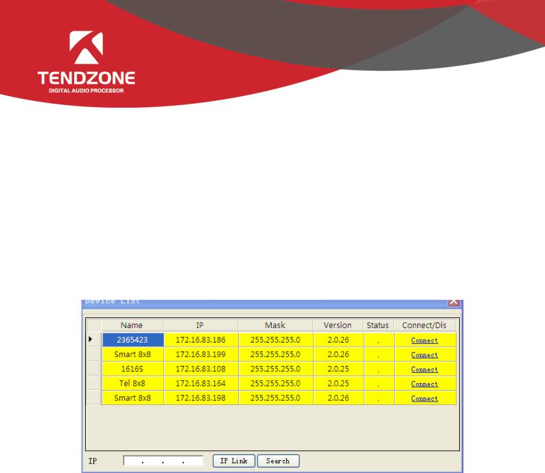
1 Device List
Figure 4
-Click “Search” to check the devices in the current local area network. The search result is shown above. Input the IP address of the device for connection.
-The status “!” means there is no IP in the PC side falling into the same network segment as the device IP address. In this case, add an IP in the PC side falling into the same network segment as the device IP address and try to connect again (Refer to FAQ 1).
-If the “Connect” is displayed in “Connect/Disconnect”, the device is not online. Click the “Connect” to connect the currently selected device. When the “Connect” is changed to “Disconnect”, the device is online successfully.
-If the “Disconnect” is displayed in “Connect/Disconnect”, the device is online. Click the “Connect” to disconnect the currently connected device. When the “Disconnect” is changed to “Connect”, the device is offline successfully.
-It is necessary to input the user’s information when “Connecting” and “Disconnecting” device.
2 Version selection: View functions of the series of products, and you can switch to the corresponding software interface.
3 Channel selection:

Figure 5
Conduct sorting, grouping and hiding operations to the input and output channel.
-Sorting: fix 1 ~ N channel; to view the position of the corresponding channel.
-Name: select the channels to be sorted, adjust the corresponding position by pressing the up key and the down key, and modify the name of corresponding channel.
-Category: display channel attributes, and cannot be modified.
-Display: selected display, otherwise hide the channel.
-Grouping: display the channel information in groups.
4)Connect: Connect the latest connected device, with a shortcut icon  .
.
5)Disconnect: Disconnect from the currently connected device, with a shortcut icon .
.
2.1.3 Device Settings
1 User Manager
Figure 6
Table 1 - Initial User List of Device

Type |
User Name |
Password |
|
|
|
Administrator |
admin |
123456 |
|
|
|
General user |
1 |
1 |
|
|
|
General user |
2 |
2 |
|
|
|
The system administrator has the right to add, delete and modify the information of general users, as well as his own information; general users can only operate their personal information. Specific procedures are as follows:
-Modify User Information: firstly, select a user to be modified in the right list and then the user's old information will appear in the User Name and Password edit box at the left side. Then, insert new information in the edit box and click the “MODIFY” button to update the user information. The updated information will be displayed in the right list.
-Delete User: select the line you want to delete at the right list and then click the “DELETE” button to delete the user.
Meanwhile, the user's information will be cleared from the right list.
-Add User: select a blank line at the right list and insert the information of a new user in the left the User Name and
Password edit box (should be blank). Click the “Add” button to add the new user. The user's information can be seen in the right list.
2 Scene Manager
Figure 7
-There are nine scenes setting options. Except "Factory Configuration" (the 0th scene) can be renamed.
-Save Scene: save the current scene to the scene number in the selected device.
-Load Scene: enable the currently selected scene; usually used to change a scene.
-Upload to Device: upload the scene in PC to the device and overwrite the selected scene on the device. Download to Local: save the currently selected device scene to PC.

3 Network Settings
Figure 8
Used to view and modify the configuration of the network address and other information, to input device's IP address, subnet mask, gateway at the corresponding position, and click “SAVE” button to change the current device's network information.
4 Serial Port Settings
Figure 9
Used to view and modify the configuration of the currently connected device serial information set and click the “SAVE” button to modify the current serial device information.
5 Voice tracking
Figure 10
The tracking adjustment, video camera parameters and MIC parameters shall be set for voice tracking.
A. The voice tracking setting can be divided into camera tracking and custom command sending. The video camera tracking is used to control the camera rotation during specking with MIC; and the custom command sending is used to send corresponding command to the corresponding port during speeching with MIC.
The tracking parameters can be activated only when the detected voice signal is more than or equal to the tracking threshold value. Otherwise, tracking will not be conducted.
The default MIC is when all MICs has no input, turn the video camera to the position of default MIC setting or send the associate command defined by default MIC. The one with # is the virtual number, which can only be used in setting default MIC.
B. The video camera setting is on a video camera debugging interface. Generally, the video camera position shall be set before tracking, and the parameters of the part will be saved in the video camera finally.
Firstly, set the serial port. There are two serial port numbers, 232 and 485 respectively, which are corresponding to the back plate connected to the clouds terrace;
Secondly, select the video camera address and protocol type. Please refer to the actual address of the video camera for the

address of video camera, and the protocol is related with the camera model;
Finally, the preset point number is the mark defined by the user for the video camera. Then adjust the upper, lower, left, right, focal length, light ring and other parameters, to define the position and settings of the video camera;
Note: a video camera can contain multiple preset points, but a preset point can only correspond to a video camera address.
Finally, click "save" to save the parameters on the video camera. "Clear" is to delete the information of the current preset point, and "call" is used to view the video camera position saved in the current preset point.
C. The number of MIC generally corresponds with the input channel, i.e. the number of channel connected to the MIC. The one with # indicates that the MIC number is the virtual number, which can only be used in setting default MIC.
The smaller the priority number is, the higher the priority level is. When the priority levels are the same, it shall be handled in accordance with the triggering priority; for example, if speech is made via two MICs, the video camera will automatically turns to the corresponding preset position of the MIC with smaller priority number (i.e. higher priority level) or send the corresponding command to the MIC with smaller priority number (i.e. higher priority level). The one of which the signal is first checked shall prevail.
To enable the MIC setting is when there are multiple MICs, all MIC parameters can be preset. During the actual use, only a few are enabled in accordance with the actual situation.
The preset point, serial port number, video camera address and protocol are generally related with the video camera, and must be corresponding to the actual connection of the video camera.
The custom command is to send the corresponding command to the defined serial port when the matrix MIC checks the input signal (usually when someone is speaking). Secondly, the command can be preset, but the "enable the custom command" shall not selected. Then the equipment will not automatically send the command, but one can still press the "send" button, to send the command in the input frame to the specified serial port at any time.
Note: both the video camera settings and the MIC settings have the preset point, serial port number, video camera address, protocol and other parameters, which shall be in accordance with the actual occasion in practical use.
For example, a video camera shall be connected with the audio processor at Port 232, and shall be disconnected and then connected with another audio processor at Port 485 without changing the position after debugging. At this moment, the parameters in the video camera shall be remained and not required to be reset. It is only required to adjust the MIC settings. However, Port 485 shall be chosen at this moment.
Click "save" to save the parameter information on the device. At this moment, the channel MIC has been associated with the corresponding video camera address. Determine whether the MIC setting is effective when enabling tracking through

"enable MIC setting" option.
Example:
Switch in the video camera with address 2 at RS232 interface, and switch in a MIC at the input channel 1 and 8 respectively (it is required that the preset point 1 be associated with the MIC of channel 1, the preset point 2 be associated with the MIC of channel 8, and the video camera turn to the MIC of the corresponding input channel). The setting process is as follows:
Connect PC with the device, and open the serial port setting in the device setting. Select 232 for the serial port number, and select 9600 for the baud rate. The check bit, data bit and stop bit shall not be changed, click "save".
A.Associate the preset point 1 and channel 1: (1). video camera settings: select 232 for the serial port number; select 2 for the video camera address; set the preset point 1; select the protocol in accordance with the actual device; adjust the upper, lower, left, right, focal length, light ring and other parameters, to align the video camera with the MIC of input channel 1, and click save button to save the save the preset point; (2) preset point control setting: select 1 for MIC number; select 2 for video camera address; select the protocol in accordance with the actual device; select 232 for the serial port number; set the preset point 1. Click enable the MIC setting; Click OK..
B.Associate the preset point 2 and channel 8: (1). video camera settings: select 232 for the serial port number; select 2 for the video camera address; set the preset point 2; select the protocol in accordance with the actual device; adjust the upper, lower, left, right, focal length, light ring and other parameters, to align the video camera with the MIC of input channel 8, and click save button to save the save the preset point; (2) preset point control setting: select 1 for MIC number; select 2 for video camera address; select the protocol in accordance with the actual device; select 232 for the serial port number; set the preset point 2. Click enable the MIC setting; Click OK..
After two MICs and video camera are associated, select enable tracking and set the tracking threshold value, to realize the voice tracking control.
6 GPIO
A.GPIO Setting
The rear panel of the audio matrix device has GPIO muddle with DB25 socket. The output channels of the upper part of the DB25 socket are channels 1~8 (whose original state is high level output), among which channels 5~8 are OC (open-collector) output with reference (driving) voltage of +12 V and maximum output current of 60 mA, and channels 1~4 are common level output with reference voltage of 3.3 V. The maximum output current is 0.4 mA when it outputs high level and -30 mA when it outputs low level.
The input channels 1~8 of the GPIO are located in the lower part of the DB25 socket of the GPIO module. The inner part of the module is equipped with put-up resistor, so the module supports 3.3 V-12 V inputs.
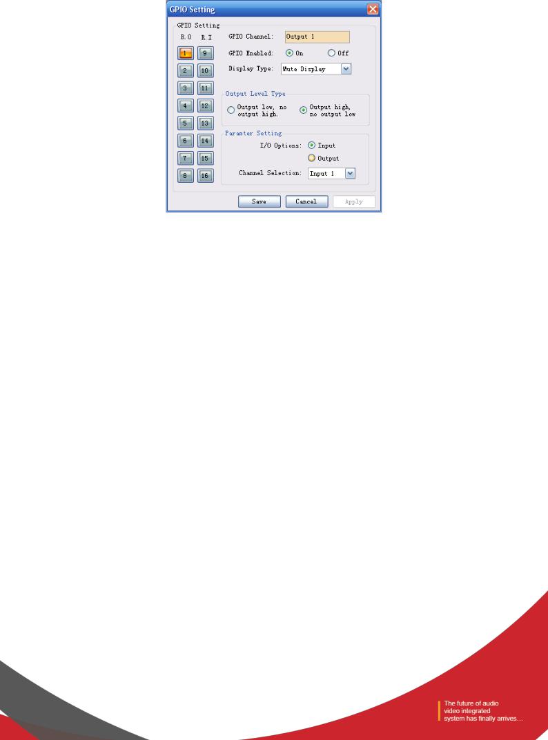
Choose one GPIO input/output channel number on the left and set the parameters of such selected channel on the right. The orange button showing certain channel number indicates that such GPIO channel is on, and the gray buttons indicate that the corresponding GPIO channels are off. Taking the above chart as example, the output channel 1 is on, and the rest channels are off.
GPIO Enabled indicates whether the settings are effective. Users can set the GPIO electrical level and parameters, and click
“Save” or “Apply” to save such settings; but such operation is only to save the PIN parameters to the device, and only when the On/Off State is set at “ON”, such settings can become effective.
It is impossible to set several GPIO channels and submit the settings at one time. After setting one GPIO channel, click
“Apply” button to save the settings before setting the next GPIO channel; and click “Save” to save the settings of the GPIO channel on the current page and exit from the current page.
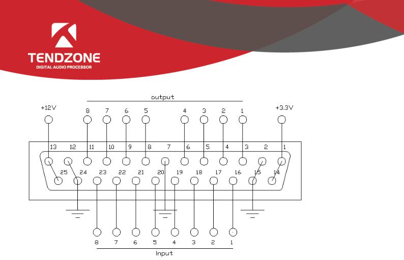
B.Definition and Wiring Demonstration of the GPIO Terminals
Two usages of GPIO:
The first usage is to output electrical level RO (RO 1~4 and RO 5~8), which means when the any parameter of the inside of the matrix changes (for example, certain channel is muted), output level of certain GPIO output pin will change subsequently and drive the external circuit;
Notes: RO 5~8 can only be connected to 12 V (can only be used with PIN-13 and PIN-25), and their outputs are OC outputs, their electrical levels are switchable, their driving current is high, and they are usually used to drive relays, buzzer or other devices with high power consumption; and outputs of RO 1~4 are ordinary electrical level outputs. The maximum output current is 0.4 mA when it outputs the high level and -30 mA when outputs at low level.
Inside of the audio matrix changes → electrical level of certain GPIO pin changes → driving external circuit.
The second usage is input RI (RI 1~8), which means when the external circuit changes, the level of certain GPIO input pin will change subsequently and trigger certain parameter of the matrix to change.
State of external circuit changes → level of certain GPIO pin changes → certain parameter of the inside of the matrix changes
Wiring Method of Output RO 5~8
Notes: RO 5~8 can only be connected to 12 V (can only be used with PIN-13 and PIN-25), and their outputs are OC outputs, their levels are switchable, their driving current is high, and they are usually used to drive relays, buzzer or other devices with high power consumption.
The 12 V reference OC output can be switched to 12 V output to be used as 12 V triggering signal for the linkage fire control.

Notes: a 10 k resistance should be connected between PIN-13 and any of the RO 5~8 to switch the OC output to 12 V. As is shown in the chart, PIN-13 outputs constant 12 V voltage; PIN-11 corresponds to RO 8 that outputs 0 or 1 according to the changes of the matrix. Such level can be used to trigger another GPIO or other devices.
The following settings should be done on the PC after the GPIO is connected in accordance with the above methods: After the device is connected to the PC → enter the GPIO Control interface → click RO 8:
(1)If the Scene Display is selected, the scene loading is selected, the scene parameter is “Scene 8”, the output electrical level is “output low no output high ”, and the GPIO Enabled State is “ON”.
The settings will become effective after the “Apply” button at the bottom is clicked.
 Loading...