

Page 1

Illustration
Thank you for purchasing our product. Please read this manual to be familiar with the product.
Note: this manual is written to provide all the relevant information for the series of models. Due to the
different signal configurations, the actual product configuration may differ from the instructions.
Page 2

Important Safety Precautions
(Instructions for Fire, Electric Shock or Personal Injury)
Note- The following basic precautions are provided for the use of the electrical appliance:
1. You should read Safety precautions carefully before using the products.
2. This product shall be grounded. In case of any fault, the current will flow to the earth through the grounding resistance
so as to reduce electric shock. The power cord and plug of product shall be properly grounded. The plug shall be inserted
into a proper socket, which shall be installed and grounded in accordance with local regulations.
Warning- Improper grounding can cause electric shock.
If you have any question on proper grounding of product, ask a qualified electrician or service personnel to check. Please
do not try to change the power plug of product. If it is not fit for the socket, ask a qualified electrician to install an
appropriate power socket.
3. To reduce injury risk, closely supervise kids when using the appliance near them.
4. Do not use the machine in a very humid place, for example, near a bathtub, wash basin, kitchen sink, and humid
basement or near a swimming pool or lake.
5. The product shall be installed in a well-ventilated place.
6. The product shall be kept away from heat sources such as electric heaters, electric blankets or other heat-generating
products.
7. The type of power supply for the product must conform to the type indicated on the appliance
8. Take care not to allow any foreign substance or liquid to fall into the appliance.
9. In case of the following, turn to qualified service personnel for repair:
A.Power cord or plug is damaged.
B.Some foreign substance or liquid has fallen into the machine.
C.The product is exposed to rain.
D.The product is not working properly or significant changes occur in the performance.
E.The product has been broken or its appearance is damaged.
10. In case of any situation not mentioned in the User Maintenance Guide, do not attempt to repair by yourself. Turn to
qualified service personnel for repair.
11. Warning - Do not allow heavy articles to stay on, or anybody step on, pull or twist any power cord. Do not abuse the
cord. A damaged power cord may cause fire or harm to human.
Page 3

Table of Content
Illustration......................................................................................................................................... 1
Important Safety Precautions ........................................................................................................... 2
Table of Content ............................................................................................................................... 3
I. Device Architecture .................................................................................................................. 4
II. Software Instructons .................................................................................................................... 6
2.1 Menu Bar and Toolbar ........................................................................................................ 7
2.1.1 File ........................................................................................................................... 7
2.1.2 Local Settings ........................................................................................................... 7
2.1.3 Device Settings......................................................................................................... 8
1)User Manager ..................................................................................................... 8
2)Scene Manager ................................................................................................... 9
3)Network Settings .............................................................................................. 10
4)Serial Port Settings ............................................................................................ 10
5)Voice tracking ................................................................................................... 11
6)GPIO .................................................................................................................. 13
7)Device Update .................................................................................................. 28
2.2 Audio input module .......................................................................................................... 28
2.2.1Input source ............................................................................................................ 30
2.2.2Exp/Gate ................................................................................................................. 31
2.2.3EQ ........................................................................................................................... 32
2.2.4Compress ................................................................................................................ 33
2.2.5AGC ......................................................................................................................... 34
2.3 Scene Control and GPIO.................................................................................................... 35
2.4Auto Mixer ......................................................................................................................... 35
2.5Ducker ................................................................................................................................ 37
2.6 SPL (Sound Pressure Level) ............................................................................................... 38
2.7Telephone control .............................................................................................................. 39
2.8 AFC .................................................................................................................................... 41
2.9AEC ..................................................................................................................................... 42
2.10 Extendeder Mixer ........................................................................................................... 43
2.11 Cobranet Mixer ............................................................................................................... 45
2.11.1 Cobrane Rreceiver Setting ................................................................................... 45
2.11.2 Cobranet Ooutput................................................................................................ 45
2.11.3 Cobranet Transmitter Setting .............................................................................. 46
2.12 Audio output module ..................................................................................................... 47
2.12.1From ..................................................................................................................... 48
2.12.2Speaker Manager .................................................................................................. 49
2.12.3 Limiter .................................................................................................................. 50
2.12.4 Output setting...................................................................................................... 51
Ⅲ.FAQ ............................................................................................................................................ 52
Page 4
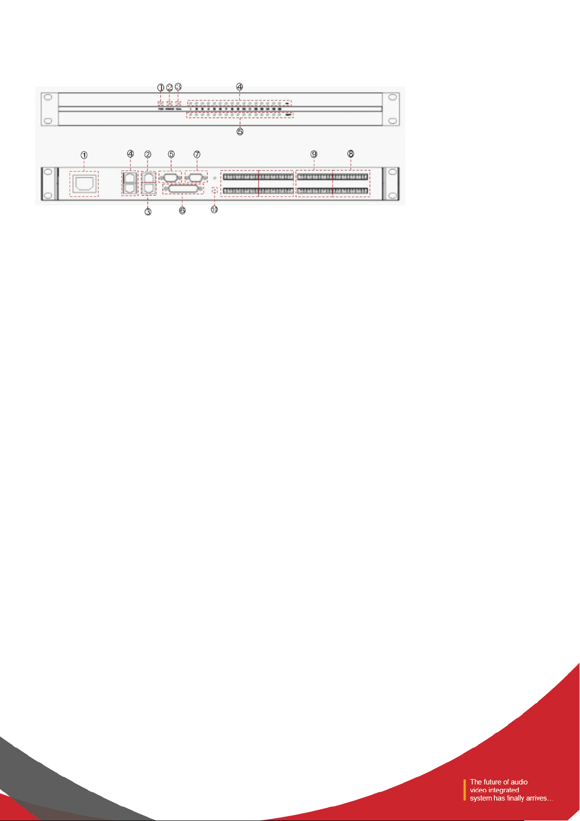
I. Device Architecture
Figure 1
The front panel of device is shown in Figure 1:
- Power indicator: after the power supply is switched on, light indicates power status.
- Status indicator: the system will run normally if the indicator is flickering and the indicator will be ON for a long time
during upgrading.
- Telephone indicator: the indicator will be ON when enabling the telephone module. Otherwise, the indicator is OFF. TC
series only.
- Input signal indicator: Illuminates when there is an input signal present. The number of indicators is equal to total
number of input channels of on the device.
- Output signal indicator: Illuminates if there is an output signal present, the number of indicators is equal to total
number of output channels on the device.
The rear panel of device is shown in Figure 1:
- AVC220V: power plug, supporting AC 100V~240V power supply, 50~60Hz, power soft switch;
- M-LAN: network interface, connect PC, on-line editing and command receiving and sending control;
- RC-LINK: external control panel interface, to connect RC panel via the network cable;
- TEL/OUT,TEL/IN:telephone access module;
- RS232: communication interface, to connect the external central control equipment / support camera tracking;
- GPIO: order transfer. For the specific connection mode, see GPIO setting in 2.1.3.6;
- RS485: support camera tracking;
Page 5

- 4---A(485+)
- 5----B(485-)
- 8---- grounding
- 485 wire on the video camera is normally blue and brown. Then the brown is +,
connecting to A on the equipment 485; and the blue is -, connecting to B on the equipment
485;
Figure 2
- INPUT: Analog audio MIC \ LINE input interface;
- OUTPUT: Analog audio output interface;
- RSET: System stem reset button;
- LANK-RX/LANK-TX: Connection (MINI T-LAN interface);
- SECONDARY/PRIMARY: Cobranet interface.
Page 6
II. Software Instructons
Installation of software: the software supports XP, win7, and vista operating systems. Before installing the software, please
make sure the computer net framework3.5 installed. Then, in the IP address of PC, there is at least an address fallen into
the same network segment as the device IP address (the default IP address ex factory is 192.168.10.10). Otherwise, the
device can be queried only and cannot be normally connected. If the PC is not provided with IP address fallen into the
same network segment as the device, please refer to the correct setting in the notes for using the device for the first time
in FAQ hereinafter.
After the PC software is properly installed, the starting interface is as shown in Figure 3:
Figure 3
- Menu bar and tool bar: the menu bar contains various function menus of the software, and the tool bar displays
function menus in common use.
- Copy / paste: parameter copy between channels or parameter copy between same functional module. The interface
choice box is red, indicating that the module can conduct copy / paste operations.
- Channel parameter control area: indicating parameters of various functional modules of each channel. The choice box
is red, indicating that the module can conduct copy / paste operations.
- Input / output channel control area: to display the electrical level and gain of each channel, select any channel, and
the corresponding specific parameters will be displayed in Module 3; part of the hidden channel can be switched
with ;When the channel choice box is red, the channel can conduct copy / paste operations. When the channel choice
box is blue, the parameters of the current channel are displayed in Module (3) .
Page 7
- Status bar: to display the current DSP occupancy factor, login status and connection status of the connecting machine.
2.1 Menu Bar and Toolbar
2.1.1 File
- New: Create a new editing file. The parameters are configured in the factory.
- Open: Load a saved scene.
- Save: Save the current configuration to the local disk..
- Exit: Close the software.
2.1.2 Local Settings
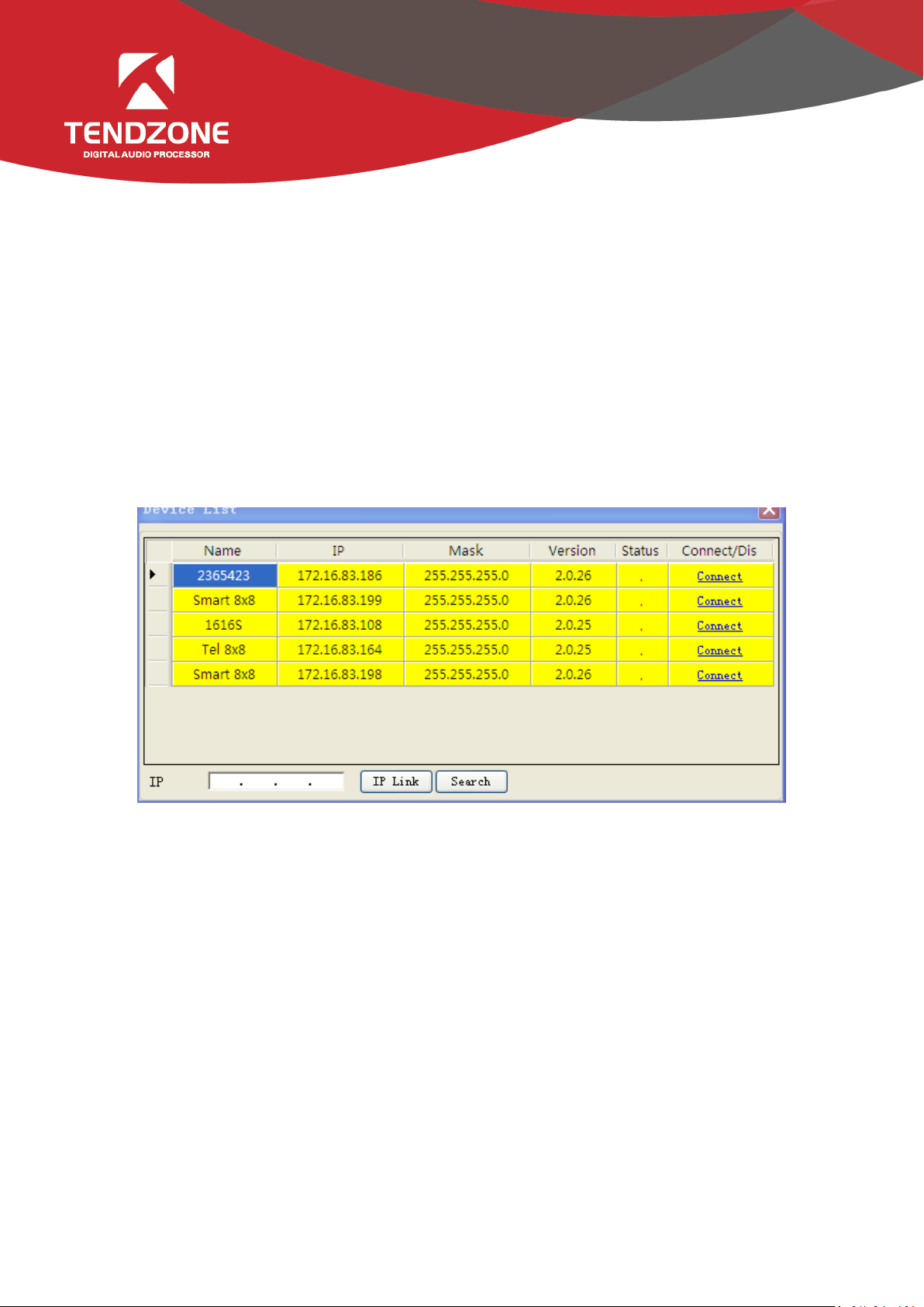
1)Device List:
Figure 4
- Click “Search” to check the devices in the current local area network. The search result is shown above. Input the IP
address of the device for connection.
- The status “!” means there is no IP in the PC side falling into the same network segment as the device IP address. In
this case, add an IP in the PC side falling into the same network segment as the device IP address and try to connect again
(Refer to FAQ 1).
- If the “Connect” is displayed in “Connect/Disconnect”, the device is not online. Click the “Connect” to connect the
currently selected device. When the “Connect” is changed to “Disconnect”, the device is online successfully.
- If the “Disconnect” is displayed in “Connect/Disconnect”, the device is online. Click the “Connect” to disconnect the
currently connected device. When the “Disconnect” is changed to “Connect”, the device is offline successfully.
- It is necessary to input the user’s information when “Connecting” and “Disconnecting” device.
2)Version selection: View functions of the series of products, and you can switch to the corresponding software interface.
3)Channel selection:
Page 8
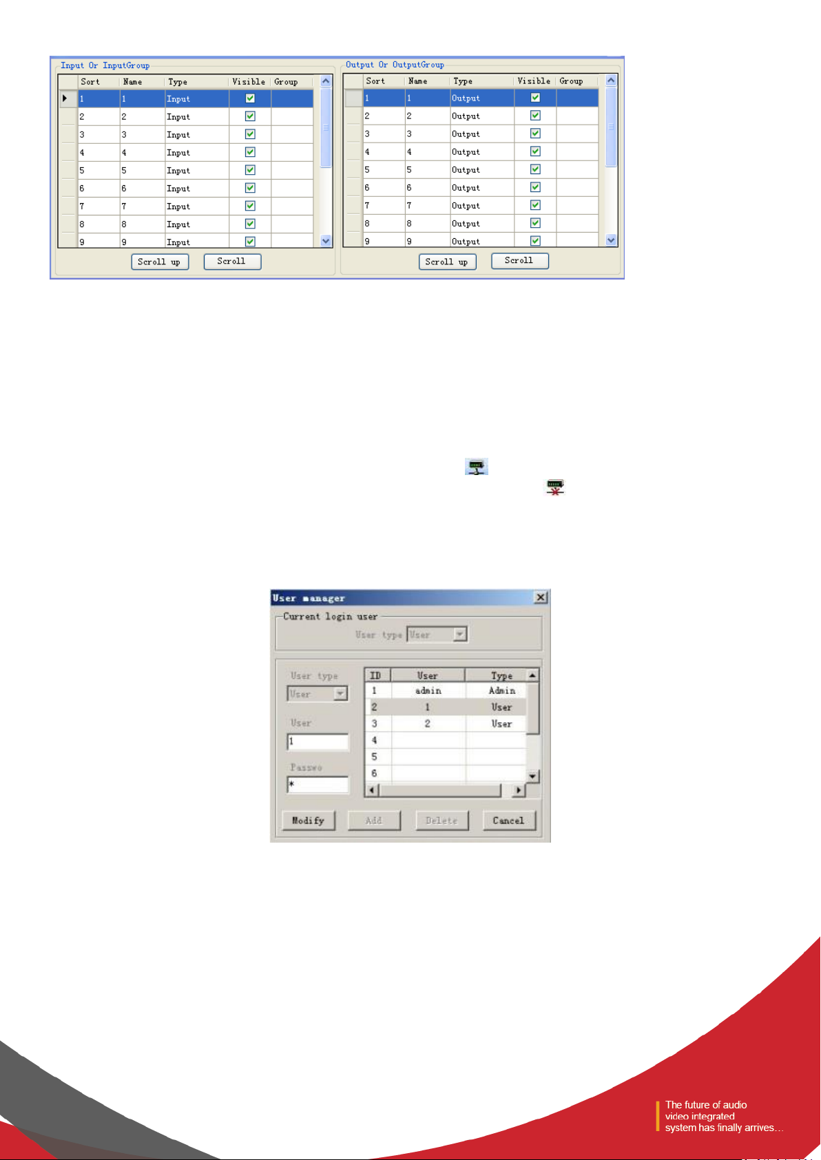
Figure 5
Conduct sorting, grouping and hiding operations to the input and output channel.
- Sorting: fix 1 ~ N channel; to view the position of the corresponding channel.
- Name: select the channels to be sorted, adjust the corresponding position by pressing the up key and the down key,
and modify the name of corresponding channel.
- Category: display channel attributes, and cannot be modified.
- Display: selected display, otherwise hide the channel.
- Grouping: display the channel information in groups.
4) Connect: Connect the latest connected device, with a shortcut icon .
5) Disconnect: Disconnect from the currently connected device, with a shortcut icon .
2.1.3 Device Settings
1)User Manager
Figure 6
Table 1 - Initial User List of Device
Page 9
Type
User Name
Password
Administrator
admin
123456
General user
1
1
General user
2
2
The system administrator has the right to add, delete and modify the information of general users, as well as his own
information; general users can only operate their personal information. Specific procedures are as follows:
- Modify User Information: firstly, select a user to be modified in the right list and then the user's old information will
appear in the User Name and Password edit box at the left side. Then, insert new information in the edit box and click the
“MODIFY” button to update the user information. The updated information will be displayed in the right list.
- Delete User: select the line you want to delete at the right list and then click the “DELETE” button to delete the user.
Meanwhile, the user's information will be cleared from the right list.
- Add User: select a blank line at the right list and insert the information of a new user in the left the User Name and
Password edit box (should be blank). Click the “Add” button to add the new user. The user's information can be seen in the
right list.
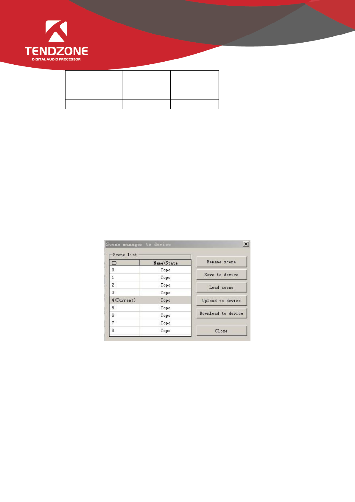
2)Scene Manager
Figure 7
- There are nine scenes setting options. Except "Factory Configuration" (the 0th scene) can be renamed.
- Save Scene: save the current scene to the scene number in the selected device.
- Load Scene: enable the currently selected scene; usually used to change a scene.
- Upload to Device: upload the scene in PC to the device and overwrite the selected scene on the device.
Download to Local: save the currently selected device scene to PC.
Page 10
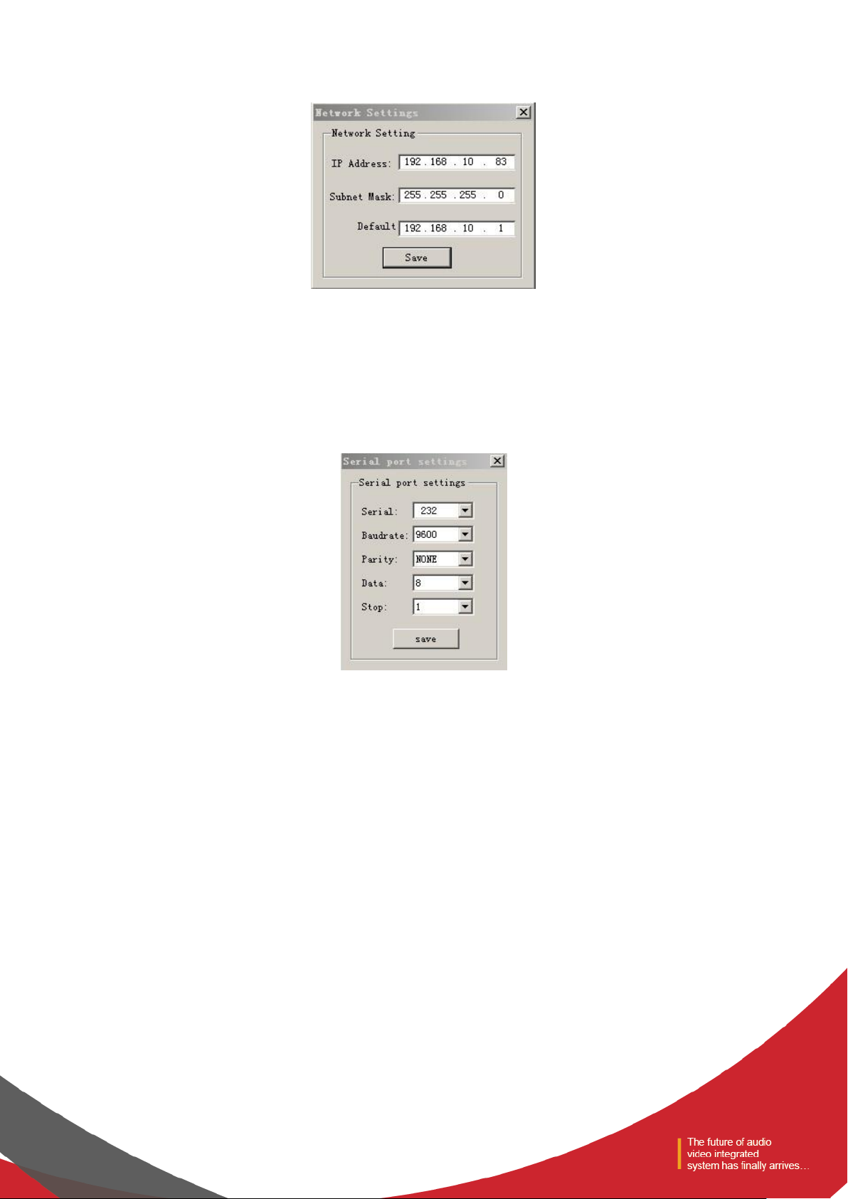
3)Network Settings
Figure 8
Used to view and modify the configuration of the network address and other information, to input device's IP address,
subnet mask, gateway at the corresponding position, and click “SAVE” button to change the current device's network
information.
4)Serial Port Settings
Figure 9
Used to view and modify the configuration of the currently connected device serial information set and click the “SAVE”
button to modify the current serial device information.
Page 11
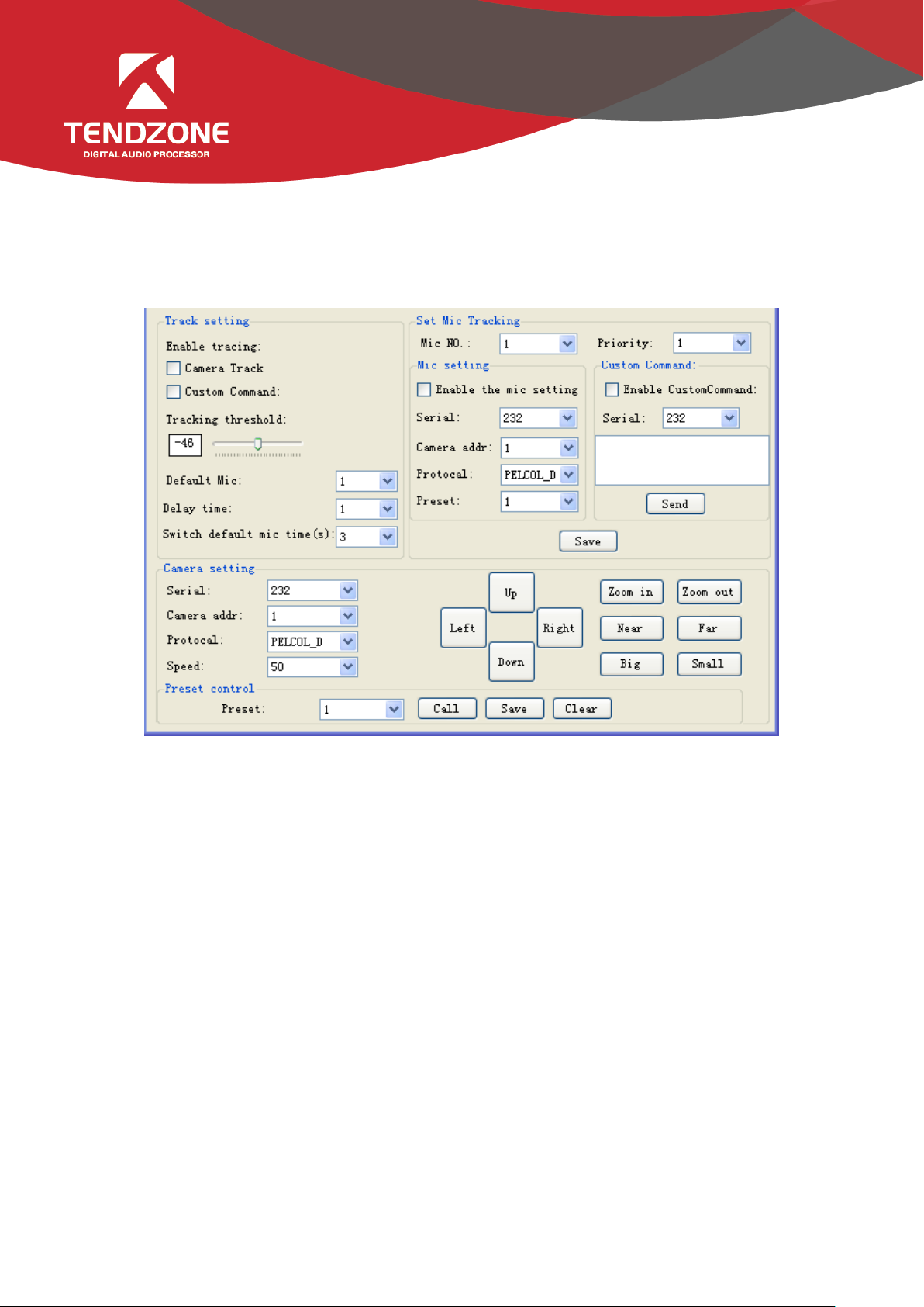
5)Voice tracking
Figure 10
The tracking adjustment, video camera parameters and MIC parameters shall be set for voice tracking.
A. The voice tracking setting can be divided into camera tracking and custom command sending. The video camera tracking
is used to control the camera rotation during specking with MIC; and the custom command sending is used to send
corresponding command to the corresponding port during speeching with MIC.
The tracking parameters can be activated only when the detected voice signal is more than or equal to the tracking
threshold value. Otherwise, tracking will not be conducted.
The default MIC is when all MICs has no input, turn the video camera to the position of default MIC setting or send the
associate command defined by default MIC. The one with # is the virtual number, which can only be used in setting default
MIC.
B. The video camera setting is on a video camera debugging interface. Generally, the video camera position shall be set
before tracking, and the parameters of the part will be saved in the video camera finally.
Firstly, set the serial port. There are two serial port numbers, 232 and 485 respectively, which are corresponding to the
back plate connected to the clouds terrace;
Secondly, select the video camera address and protocol type. Please refer to the actual address of the video camera for the
Page 12

address of video camera, and the protocol is related with the camera model;
Finally, the preset point number is the mark defined by the user for the video camera. Then adjust the upper, lower, left,
right, focal length, light ring and other parameters, to define the position and settings of the video camera;
Note: a video camera can contain multiple preset points, but a preset point can only correspond to a video camera
address.
Finally, click "save" to save the parameters on the video camera. "Clear" is to delete the information of the current preset
point, and "call" is used to view the video camera position saved in the current preset point.
C. The number of MIC generally corresponds with the input channel, i.e. the number of channel connected to the MIC.
The one with # indicates that the MIC number is the virtual number, which can only be used in setting default MIC.
The smaller the priority number is, the higher the priority level is. When the priority levels are the same, it shall be
handled in accordance with the triggering priority; for example, if speech is made via two MICs, the video camera will
automatically turns to the corresponding preset position of the MIC with smaller priority number (i.e. higher priority level)
or send the corresponding command to the MIC with smaller priority number (i.e. higher priority level). The one of which
the signal is first checked shall prevail.
To enable the MIC setting is when there are multiple MICs, all MIC parameters can be preset. During the actual use, only a
few are enabled in accordance with the actual situation.
The preset point, serial port number, video camera address and protocol are generally related with the video camera, and
must be corresponding to the actual connection of the video camera.
The custom command is to send the corresponding command to the defined serial port when the matrix MIC checks the
input signal (usually when someone is speaking). Secondly, the command can be preset, but the "enable the custom
command" shall not selected. Then the equipment will not automatically send the command, but one can still press the
"send" button, to send the command in the input frame to the specified serial port at any time.
Note: both the video camera settings and the MIC settings have the preset point, serial port number, video camera address,
protocol and other parameters, which shall be in accordance with the actual occasion in practical use.
For example, a video camera shall be connected with the audio processor at Port 232, and shall be disconnected and then
connected with another audio processor at Port 485 without changing the position after debugging. At this moment, the
parameters in the video camera shall be remained and not required to be reset. It is only required to adjust the MIC
settings. However, Port 485 shall be chosen at this moment.
Click "save" to save the parameter information on the device. At this moment, the channel MIC has been associated with
the corresponding video camera address. Determine whether the MIC setting is effective when enabling tracking through
Page 13

"enable MIC setting" option.
Example:
Switch in the video camera with address 2 at RS232 interface, and switch in a MIC at the input channel 1 and 8 respectively
(it is required that the preset point 1 be associated with the MIC of channel 1, the preset point 2 be associated with the
MIC of channel 8, and the video camera turn to the MIC of the corresponding input channel). The setting process is as
follows:
Connect PC with the device, and open the serial port setting in the device setting. Select 232 for the serial port number,
and select 9600 for the baud rate. The check bit, data bit and stop bit shall not be changed, click "save".
A. Associate the preset point 1 and channel 1: (1). video camera settings: select 232 for the serial port number; select 2 for
the video camera address; set the preset point 1; select the protocol in accordance with the actual device; adjust the upper,
lower, left, right, focal length, light ring and other parameters, to align the video camera with the MIC of input channel 1,
and click save button to save the save the preset point; (2) preset point control setting: select 1 for MIC number; select 2
for video camera address; select the protocol in accordance with the actual device; select 232 for the serial port number;
set the preset point 1. Click enable the MIC setting; Click OK..
B. Associate the preset point 2 and channel 8: (1). video camera settings: select 232 for the serial port number; select 2 for
the video camera address; set the preset point 2; select the protocol in accordance with the actual device; adjust the upper,
lower, left, right, focal length, light ring and other parameters, to align the video camera with the MIC of input channel 8,
and click save button to save the save the preset point; (2) preset point control setting: select 1 for MIC number; select 2
for video camera address; select the protocol in accordance with the actual device; select 232 for the serial port number;
set the preset point 2. Click enable the MIC setting; Click OK..
After two MICs and video camera are associated, select enable tracking and set the tracking threshold value, to realize the
voice tracking control.
6)GPIO
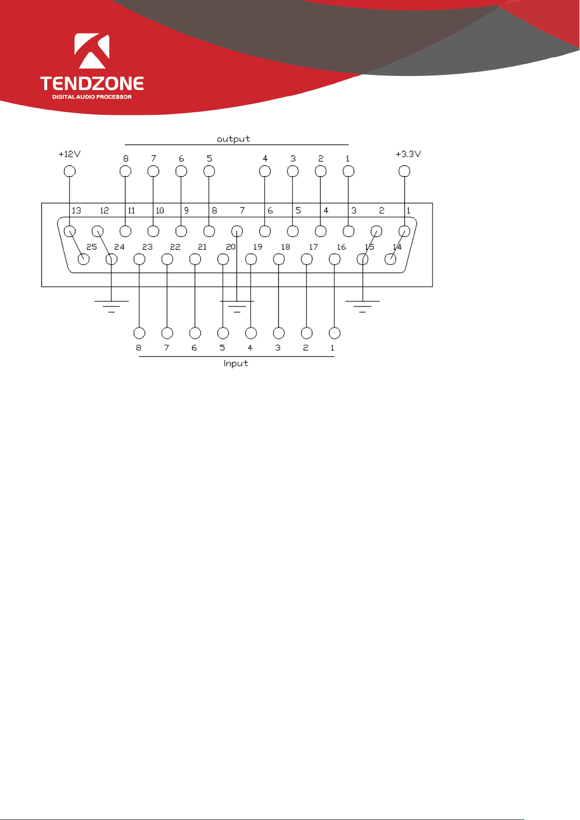
A. GPIO Setting
The rear panel of the audio matrix device has GPIO muddle with DB25 socket. The output channels of the upper part of
the DB25 socket are channels 1~8 (whose original state is high level output), among which channels 5~8 are OC
(open-collector) output with reference (driving) voltage of +12 V and maximum output current of 60 mA, and channels
1~4 are common level output with reference voltage of 3.3 V. The maximum output current is 0.4 mA when it outputs
high level and -30 mA when it outputs low level.
The input channels 1~8 of the GPIO are located in the lower part of the DB25 socket of the GPIO module. The inner part of
the module is equipped with put-up resistor, so the module supports 3.3 V-12 V inputs.
Page 14
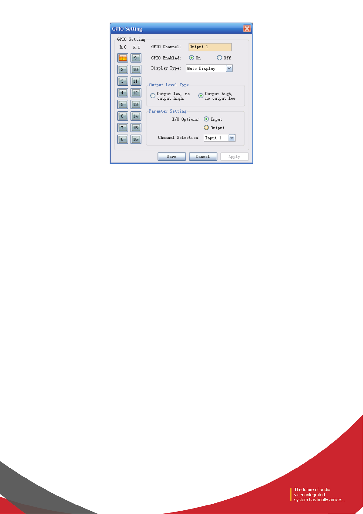
Choose one GPIO input/output channel number on the left and set the parameters of such selected channel on the right.
The orange button showing certain channel number indicates that such GPIO channel is on, and the gray buttons indicate
that the corresponding GPIO channels are off. Taking the above chart as example, the output channel 1 is on, and the rest
channels are off.
GPIO Enabled indicates whether the settings are effective. Users can set the GPIO electrical level and parameters, and click
“Save” or “Apply” to save such settings; but such operation is only to save the PIN parameters to the device, and only when
the On/Off State is set at “ON”, such settings can become effective.
It is impossible to set several GPIO channels and submit the settings at one time. After setting one GPIO channel, click
“Apply” button to save the settings before setting the next GPIO channel; and click “Save” to save the settings of the GPIO
channel on the current page and exit from the current page.
Page 15
B. Definition and Wiring Demonstration of the GPIO Terminals
Two usages of GPIO:
The first usage is to output electrical level RO (RO 1~4 and RO 5~8), which means when the any parameter of the inside of
the matrix changes (for example, certain channel is muted), output level of certain GPIO output pin will change
subsequently and drive the external circuit;
Notes: RO 5~8 can only be connected to 12 V (can only be used with PIN-13 and PIN-25), and their outputs are OC outputs,
their electrical levels are switchable, their driving current is high, and they are usually used to drive relays, buzzer or other
devices with high power consumption; and outputs of RO 1~4 are ordinary electrical level outputs. The maximum output
current is 0.4 mA when it outputs the high level and -30 mA when outputs at low level.
Inside of the audio matrix changes → electrical level of certain GPIO pin changes → driving external circuit.
The second usage is input RI (RI 1~8), which means when the external circuit changes, the level of certain GPIO input pin
will change subsequently and trigger certain parameter of the matrix to change.
State of external circuit changes → level of certain GPIO pin changes → certain parameter of the inside of the matrix
changes
Wiring Method of Output RO 5~8
Notes: RO 5~8 can only be connected to 12 V (can only be used with PIN-13 and PIN-25), and their outputs are OC outputs,
their levels are switchable, their driving current is high, and they are usually used to drive relays, buzzer or other devices
with high power consumption.
The 12 V reference OC output can be switched to 12 V output to be used as 12 V triggering signal for the linkage fire
control.
Page 16
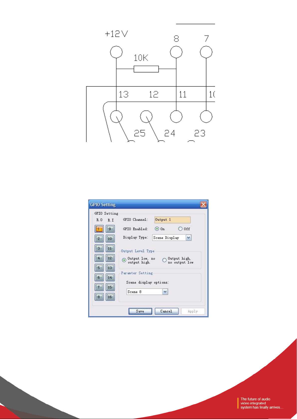
Notes: a 10 k resistance should be connected between PIN-13 and any of the RO 5~8 to switch the OC output to 12 V. As is
shown in the chart, PIN-13 outputs constant 12 V voltage; PIN-11 corresponds to RO 8 that outputs 0 or 1 according to the
changes of the matrix. Such level can be used to trigger another GPIO or other devices.
The following settings should be done on the PC after the GPIO is connected in accordance with the above methods:
After the device is connected to the PC → enter the GPIO Control interface → click RO 8:
(1) If the Scene Display is selected, the scene loading is selected, the scene parameter is “Scene 8”, the output
electrical level is “output low,no output high ”, and the GPIO Enabled State is “ON”.
The settings will become effective after the “Apply” button at the bottom is clicked.
Page 17

If Scene 8 is loaded on the scene management interface, PIN-11 (i.e. RO 8) will output 0, and remain the same before
other scenes are loaded, at which time PIN-11 (i.e. RO 8) will output 1;
(2) The specific settings are as follows if Level Display is selected:
When it works,
As the level of input channel 1 of the audio matrix reaches -28 dB, PIN-11 (i.e. RO 8) will output 0, and remain the same
before the level decreases, at which time PIN-11 will output 1.
(3) The specific settings are as follows if Mute Display is selected:
When it works,
As the input channel 3 of the matrix is muted, PIN-11 (i.e. RO 8) outputs 1 and remains the same before the input channel
3 is not muted, at which time PIN-11 outputs 0.
(4) The specific settings are as follows if System Mute Display is selected:
Page 18

When all the output channels of the audio matrix are muted, PIN-11 (i.e. RO 8) outputs 0, and remains the same before
any channel is not muted, at which time PIN-11 outputs 1.
Example 2: OC Output Drives a Relay (RO 5~8)
The relay can be used to control alarm devices or other device
PIN-25 outputs 12 V voltage and PIN 8-11 (i.e. RO 5 ~ 8) control the relay according to changes of the matrix state.
The scene type is set at Scene Display for RO 8 on the PC interface as follows:
Page 19

When Scene 4 of the matrix is loaded, PIN-11 (i.e. RO 8) outputs low level, there is current running through the relay, and
the relay is switched; and when the matrix is switched to other scenes (such as Scene 3), PIN-11 (i.e. RO 8) outputs no
level, there is no current running through the relay, and the relay is not switched.
The actions are opposite if “output high, no output low” is selected.
If RO 8 has other biding parameters, such as level display, channel mute display, system mute display, etc., the working
conditions of the relay will be switched according to the changes of the matrix parameters.
1.2 Wiring Method of Output RO 1~4
Notes: outputs of RO 1~4 are ordinary 5 V outputs. Working modes of RO 1~4 and those of RO 5~8 are consistent, but the
output high voltage of RO 1~4 is 5 V. The maximum output current is 0.4 mA when it outputs the high level and -30 mA
when outputs at low level.
Example 1: Direct Electrical Output
Settings of RO 1 on the PC interface are as follows:
Page 20

When Scene 6 of the matrix is loaded, PIN 3 outputs low level (< 0.7 V); and when scenes other than Scene 6 are loaded,
PIN 3 outputs high level (> 4 V).
1.3 Wiring Method of Input RI 1~8
Example 1:
In the above chart, connecting switch of PIN-16 (RI 1) (inputs low level) is closed;
The settings are as follows when Scene Setting of RI 1 is selected on the PC interface: the matrix will load Scene 4
automatically if the level of the pin corresponding to RI 1 is “Falling Edge”.
Page 21

If the state of the switch in the above chart is changed from “open” to “closed”, the level of PIN-16 will be changed from
“high level” to “low level”, and then a falling edge will be formed so that the matrix will load Scene 4 automatically.
If the state of the switch in the above chart is changed from “closed” to “open”, the level of PIN-16 will be changed from
“low level” to “high level”, and then a rising edge will be formed so that the matrix will remain the same.
Example 2:
As is shown in the chart, PIN-16 (i.e. RI 1) and PIN-15(grounding) are connected to a 3.3-12 V output system,
And then select Mixer Setting for RI 1 on the PC:
Page 22

When the external triggering signals are rising from low values, PIN-16 (i.e. RI 1) generates a rising edge, which will cause
the sound mixing function of the contact corresponding to the sound mixer to be turned on.
C. Basic Attribute of GPIO Input Channel RI
a) GPIO Channel: display the number of the input channel being set currently.
b) GPIO Enabled: set the parameters of the channel at On state.
c) Display Type includes Scene Setting, Mixer Setting, Volume Setting, Channel Mute Setting, Mute System and Serial
Command Setting.
Control type has 2 basic attributes:
1) Trigger Mode: categories of trigger types depend on control types, and there are at most 4 triggering modes (Rising
Edge Trigger; Falling Edge Trigger; Rising Edge Selection and Falling Edge Trigger Cancellation; and Falling Edge
Selection And Rising Edge Cancellation); and Rising Edge refers to the fact that electrical level of the GPIO input
channel pins is changed from low to high; and Falling Edge refers to the fact that the level of the GPIO input channel
pins is changed from high to low.
2) Parameter Setting: parameter setting depends on control types, and different control types allow different parameter
settings.
a) Scene Setting
Page 23

As is shown in the above chart, the audio matrix will load Scene 2 automatically when the level of GPIO input channel 1 is
changed from low to high.
b) Mixer Setting
When the GPIO Channel is input 2, the mixer setting should be selected as the Control Type. As is shown in the chart, when
the level of GPIO input channel 2 is changed from low to high, the sound mixing contacts corresponding to input channel 2
and output channel 5 will be opened, and the signals of input channel 3 will be mixed and transmitted to output channel 5
and then the signals will be output. If the trigger type is trigger mode 4 (Falling edge of the open, rising off), the contacts
corresponding to the input channel 3 and output channel 5 of the key sound mixer will be closed when electrical level of
the pin of GPIO input channel 2 is changed from low to high.
c) Volume Setting
Page 24

Input/output type refers to the input sound volume/output sound volume of the control system. Gain Step refers to the dB
change corresponding to the step of the adjusted sound volume due to each trigger; and there are two effects, i.e.
Increase and Decrease, which refers to the increased or decreased sound volume caused by each trigger.
As is shown in the chart, the level of input channel 1 will be increased by 5 dB when electrical level of GPIO input channel 3
is changed from low to high.
d) Channel Mute Setting
As is shown in the chart, output channel 4 is be muted when the level of the pin of GPIO output channel 4 is changed from
low to high.
e) System Mute Setting
Page 25

As is shown in the chart, all the system output channels are muted when the level of GPIO input channel 5 is changed from
low to high.
f) Serial Command Setting
Parameter setting: input hexadecimal orders (0~9 and A~F). Two characters constitute one effective order, and if there is
only one character, a 0 should be added before such bit, such as 03, 0A, etc. Bland space will be added after each two
characters for the convenience of reading automatically by the interface. The blank spaces will be filtered off before the
orders are transmitted, so the transmitted orders consist of successive hexadecimal characters.
As is shown in the above chart, the system will perform the hexadecimal order when the level of GPIO input channel 6 is
changed from low to high.
Notes: the input characters must hexadecimal characters, otherwise the order will not be approved, and such transmission
will fail.
D. Basic Attributes of GPIO Output Channels:
Page 26

a) GPIO Channel: display the number of the output channel being set currently.
b) GPIO Enabled: set the parameters of the GPIO channel at ON state.
c) Display Type: scene display, level display, channel mute display and system mute display.
Display type has two basic attributes:
Output Level Type: depends on display type and has only two modes. Categories of output level types depending on actual
external inputs of the GPIO are as follows:
Output level type 1: output low, no output high: refers to the fact that GPIO outputs low level when the audio matrix
meets the relevant outputting requirements, otherwise the GPIO outputs high level.
Output electrical level type 2: output high, no output low: refers to the fact that GPIO outputs high level when the audio
matrix meets the relevant outputting requirements, otherwise the GPIO outputs low level.
1) Parameter Setting:
Parameter settings depend on the display types. Different display types allow different parameter settings.
a) Scene Display
As is shown in the chart, pin of GPIO output channel 1 outputs low level when the audio matrix loads the default scene.
b) Level Display
Page 27

As is shown in the chart, pin of GPIO output channel 2 outputs low level when the level of audio matrix input channel 1
reaches -20dB.
c) Muted Channel Display
As is shown in the chart, pin of GPIO output channel 3 outputs low level when the audio matrix output channel 3 is muted.
d) Muted System Display
As is shown in the chart, pin of GPIO output channel 4 outputs low level when all the output channels of the audio matrix
are muted.
Page 28

7)Device Update
To download the upgrade package from the official website, input the directory of the upgrade package in the address bar,
and click "upgrade" to complete device upgrade. The device will reboot after upgrade, but manual connection is required.
2.2 Audio input module
Figure 23
The interface can display 8 channels at most, which can be switched by pressing key; click the channel to switch
the above functional module display box. See 2.1.2.3 for the channel information.
The input channel supports grouping function, and multiple channels can set to a group. When the gain of the group is
adjusted, the gain of the subordinate channel is also changed. The grouping identification will be on the gain fader after
grouping. The system provides two groups: one is GROUP group, to directly adjust the gain value; the other is DCA group,
to adjust the gain percentage.
1) The above edit box displays the channel name, which can be modified.
2) The lamp indicates whether the channel has external control panel input, with 3 states: on, off and flash, which
depends on whether call is allowed in the input source.
Page 29

Lamp state
Whether call is allowed in the
channel.
Whether there is panel MIC signal
input in the channel.
On
Yes
Yes
Off
Yes / No
No
Flash
No
Yes
Figure 24
3) PRE/POST: the electrical level displayed is before or after fader.
4) Level display and input gain adjustment fader
5) Input gain
Page 30

2.2.1Input source
Figure 25
The sensitivity of MIC input and line input can be selected. High sensitivity indicates high acoustic-electric conversion
efficiency of the MIC, and sensitive reflection of weak voice signal;
Allow call: allow the access of panel signal to the channel. Down indicates access, and up indicates access is not allowed.
- Telephone input: allow the access of the phone module signal to the channel. Down indicates access, and up indicates
access is not allowed.
- Mute: down indicates the channel enables mute, i.e. the input signal is shielded, and up indicates the channel signal is
not mute.
- Test signals: including sine, pink and white noise. The parameters of the signal generator can be adjusted when pressed,
the signal of the signal generator access the channel, and other input signals are no longer output;
- Phantom power: MIC input is provided with phantom power, for condenser microphone. It shall not be turned on in
case of line input or non-condenser microphone, so as to prevent overburning;
Page 31

2.2.2Exp/Gate
Figure 26
The expander will add dynamic range to the input according to needs of the user. When the signal input is less than
“threshold”, the expander amplifies and outputs the signal input by the “ratio” set. Level output = threshold – (threshold –
level input)/ratio; when the signal input is more than “threshold”, it is output by 1:1. Level output = level input, when the
ratio is adjusted by the maximum value (∞), the expander becomes a noise gate.
- Bypass: the signal input is bypassed and the signal will go directly to the next processing module. If it is pressed the
expander will not be enabled; otherwise, the expander will be enabled.
- Ratio: the dB of dynamically changed signal input of the expander/the dB of dynamically changed signal output of the
expander.
- Attack time: less than the time needed of the signal input of “threshold” of the expander from the entering into the
expanding status to output by the setting of expanding ratio.
- Release time: the time needed for the signal input returning to the original non-expanding status from the expanding
status.
- All reset: all parameters are reset to the factory settings.
Page 32

2.2.3EQ
The equalizer is used to compensate and modify the frequency characteristics, so that it can achieve the characteristic of
relatively flat frequency response Different models of equalizers are of different types, and the specific type shall be
subject to the actual model of the device.
Figure 27 5 band paragraph EQ
- The equalizer is to compensate and correct the frequency characteristics to make it reach a true and straight
frequency response characteristic.
- Bypass All: bypass all bands, the signal directly to the next processing module. Press down shows that EQ is disabled,
when popped up shows the EQ is enabled.
- Band Bypass: Range through-pass: after equalizer adjustment, you can cancel the bypass of certain set frequency
ranges. As long as you click to select the corresponding frequency range button, you can restore the original 0dB status,
inactivating the bypass of this band without affecting others.
- Center frequency: the frequency that needs equalization processing shall be between 20Hz and 20000Hz. When we
change the value, the icon of equalizer will also react synchronously.
- Gain: the gain/attenuation at the center of frequency. When the value is 0, the center frequency and Q value shall be
invalid.
- Q value: It means the bandwidth of frequency point. The more the value, the larger the bandwidth will be.
Page 33

Figure 28 31 band graphics EQ
- Bypass: the signal input is bypassed and not be processed.
- Gain: the gain/attenuation at the center of frequency. When the value is 0, the center frequency and Q value shall be
invalid.
- Flatten: all band gain recovery to 0dB.
- Narrow Band: bandwidth (Q), value is smaller than normal.
- Normal: bandwidth (Q), value is common bandwidth.
- Wide Band: bandwidth (Q), value is larger than normal.
2.2.4Compress
Figure 29
The compressor is to compress the signal by the preset ratio when input signal level more than threshold. When the input
Page 34

level is more than the preset threshold, the output level is compressed by the ratio set. Signal Output = Threshold + (Signal
Input - Threshold) / Ratio; if the input level is less than preset threshold, the signal will be directly output. Signal Output =
Signal Input; when the ratio is adjusted by “+∞”, the compressor becomes as a limiter.
- Bypass: the input signal is bypassed and will not be processed. If it is pressed, the compressor will be disabled.
Otherwise, the compressor will be enabled.
- Threshold: is the initial level of compression. When the signal is more than this limit value, the compression processing
module will be enabled to compress the signal; when the signal is less than this limit value, the compression processing
module will be disabled and the signal input will be fed directly to the output.
- Ratio: the compression ratio of signal over threshold.
- Release time: the time from the level input is less than preset value to that the compressor fully stops operating.
- Attack time: the time from the level input reaches the threshold to that the compressor starts.
- Output: the actually compressed level value.
2.2.5AGC
Figure 30
First, the function of AGC is described. For example, when the user speaks facing towards the microphone, the distance
between the mouth and the microphone will fluctuate, causing fluctuating volume output. Though setting the threshold,
AGC outputs the signal input by 1:1 if the level less than threshold while the level over the threshold will be directly raised
by ratio. The target level is properly set so that the sound signal may be output stably.
AGC control is to automatically control range of gain through changing I/O compression ratio. When the weak signal is
Page 35

input, the signal will be amplified to ensure the strength of the sound signal output; when the signal strength input
reaches to the certain extent, the signal will be compressed to lower the range of output.
- Input: the level of input automatic gain controller.
- Output: the level of output automatic gain controller.
- Threshold: it is the initial level of automatic gain. When the signal is less than this limit value, the automatic gain
processing module will be enabled to gain the excessively small signal.
- Bypass: the signal input is bypassed and not be processed.
2.3 Scene Control and GPIO
Figure 31
The Scene Control section includes Select scene, Upload, Save and Load. The scene with yellow background is running
scene.
- Save means to save the selected scene configuration to the local (note: it is not the same as the storage of scene in the
“File” menu. As for the latter, the configuration currently in use by the device will be saved to the local).
- Upload: overwrite scene configuration in scene list on the device with the local configuration file. Click“load”,the scene
enabled.
- Load: set the selected scene settings as the currently running scene.
GPIO interface only shows the interface, 16 GPIO indicators shows the current GPIO pin high or low level. GPIO pin level is
high, the display light turns red; GPIO pin level is low, the display lights turn green. Refer to the GPIO setting in the menu
in detail.
2.4Auto Mixer
In the meeting room, 10 microphones, if 10 microphones are open and have the same level, and only one person in the
speech cause the remaining 9 microphones will pick up the room noise, reverberation sound, affect the audio quality.
Secondly, because of these standby microphones, the effective acoustic components of the maximum gain before the
sound feedback would relatively decline and cause volume inadequacy.
Automatic mixer adjust gain from each input channel in real-time to adapt the general level, through improving the high
Page 36

signal gain, reducing low level signal gain to maintain the overall system gain.
In the gain distribution type automatic mixer, a channel is not exactly open or closed, but located any state arbitrarily.
Relatively speaking, if the volume channel is higher, the gain is higher too . If several channels volume are the same, then
gains are equal. If a channel is almost no signal through, it almost no gain.
Figure 32
Each channel of automatic mixer has input, gain level meter and an automatic gain, channel fader, priority, and channel
muting.
Channel control: each channel has an automatic" AUTO " button, turn on the channel into the automatic mixing. If you
need a background music channel at a fixed level, or need to be a "chairman" Mic always remains in the open state, then
you need to push the “AUTO” off button on the automatically key. When a channel to select" AUTO " off the automatically
key, the gain will be automatically regulated, the channel signal level will not affect the other channel gain ( such as no
longer affects automatic mixer gain calculation ).
Channel mute and fader are automatic gain type, i.e., no matter how you act; there is no effect on automatic mixer. It
means that a particular channel is silent, if the high level signal on the channel is present, the remaining channels’ level
would also reduce. In order to mute a signal and prevent the signal effect automatic mixing, please open the mute and
turn “AUTO” off automatic mixer. Each channel of the mute function is to mute the channel in mix and mute the output
channel directly. Channel fader control the channel mix level and output level directly.
Priority control PR: allows the priority level high channel exceeding level of low passage, thus affecting the automatic audio
mixing algorithm.
The control grades from number 0 (lowest priority) to 10 (highest priority) the numerical definition of priority, the default
value is 5 (standard priority). User can control priority through the slider, also click on the edit box and enter the number
between 0 - 10 data adjusting priority. If the 2 channels are receiving a signal having the same level, high priority channel
will be a higher gain. Channels between each difference of 1 priority" units", the gain will differ 2dB ( if Slope is set in 2 ).
For example, in channel 1's priority is set to 6, channel 2 priority is set to 3, when the two channel receiving the same level
Page 37

signal, channel 1 is 26dB more gain than channel 2. Obviously, the slope setting affects the priority weights. When Slope is
set to 3.0, difference between each channel is 1 priority" units", the gain will differ 3dB.
If all channels of equal priority, please set all channel priority to 5.
Note: when the channel priority differences for extreme cases, such as 1 and 10, must be more circumspect. High priority
from the speaker up to very large signal, background noise, will" masking" out the low priority channel, even when it is not
in use, higher slope value will further exacerbate the problem.
2.5Ducker
Main function of ducker module: if the signal from one channel is selected as the control signal, the module is used to
decrease the effect of the signal from its adjacent channel. Its main application includes conference rooms.
For example, if the audio input from the rostrum selected as the control signal, the audio output from others will be
decreased when the main speaker speaks out and thus it seems there is only one person speaking.
Also for example, background music will be played during normal business in a shopping mall. When broadcasting a notice
or tip, the music will be automatically closed at the time of human voice insertion and will be automatically restored after
sound has been disappeared. Here the ducker is valid.
Figure 33
1. As shown in the input channel on the "on" / "off" button (the number of channels and devices are the same number of
physical input channels), choose the way that needs to be dodge input channel "open" (the music signal channel), the
channel will be automatically in the main mixer to open in DUCK signal in the other inputs can not be mixing process.
2. As shown in “paging input” in the menu, select it as a way to dodge the signal input channels (the MIC signal channel).
- Bypass : bypass the input signal and do not duck it.
- Threshold: the initial level for ducking, when the signal is above this limit, the ducker processing module will start to
duck the excessively large signal.
- Depth: once the bypassing signal exceeds the threshold specified, the gain can be reduced by adjusting the range of
the threshold.
- Attack time: the time to reduce the gain if the bypassing signal exceeds the threshold specified.
- Hold time: the time to hold the setting status when the gain is reduced.
- Release time: if the input signal is lower than the specified value, the audio channel will not be immediately shut down
and a delay will be given based on the specified value. During the delay, the audio channel will be activated again if only
Page 38

the signal is greater than “Threshold”.
- Level attenuation (Reduction): level after being processed by the module for a user’s view.
2.6 SPL (Sound Pressure Level)
Automatic Noise Canceller module according to the ambient noise level automatically adjusts input signal level, input
signal level increases as the ambient noise increased.
Such as a sports stadium, the appreciation in the audience concentrate on the game, the venue environment quieter, the
sound output does not need at this time a great announcer, but when the audience cheers or warm atmosphere when the
announcer's voice output will large, so as not to drown the voice of the audience. ANC role is to specify the output will
increase as the ambient noise increases, when used as a monitor, monitor the surrounding noise, the other MIC as a
working microphone, for voice input.
Figure 34
1. The "on" / "off" button (the number of channels and devices are the same number of physical input channels), choose
to work the way that the signal channel input channel "open" (the broadcast channel), the channels will be automatically
in the main mixer in the SPL signal to open, in the other inputs can not be mixing process.
2. As shown in “sense input” in the menu, select the microphone that monitors all the way as the input channel.
- Gain display: top window shows the gain through the module (assuming there is no bypass).
- Bypass: press the button to bypass the module and the input will be sent to the output without change.
- Maximum Gain: the maximum allowable signal gain in dB, it defines the upper limit of output volume when the
ambient sound is very loud. It can be adjusted by the fader, or click on the file to enter a dialog box and directly define a
value. This value cannot be less than the minimum gain.
- Minimum Gain: it defines the most insignificant sound output when the ambient is very quiet. The fader can be
adjusted, or click on the file to enter a dialog box and directly define a value. Step for fine-tuning 0.01 dB. This value
cannot be more than the maximum gain.
- Gain Ratio: control the gain changes relative to the change of peripheral level. If the value is set to around 1.0:1, it
means the level increases / decreases by 1dB, SPL gain will increases / decreases by 1dB. A higher value, such as 2.0:1,
means as compared with the increase of peripheral level, the gain increases even more and is often used in noisy
environments. A lower value, such as 0.5:1, means the increase of peripheral level by 1dB, the gain only increases /
decreases by 1dB and thus the effect is less obvious than before.
- Speed: control the change rate of module, it shows in seconds. longer time means when the peripheral level changes,
Page 39

the gain gradually increases or decreases; and vice versa.
- Gap threshold: level control when the audio (program) level is so low that it can be regarded as “intermittent”. when
the audio (program) level is lower than the level and the duration is at least the intermittence time, the intermittent
detection LED will light up and SPL will respond to the peripheral level. When the audio (program) level is higher than the
level, SPL will not be adjusted according to the peripheral level. In the case, the level must be set so that the LED can also
light up when the audio (program) signal is so weak that the microphone is unable to pick up enough program signal and
the signal picked up is almost the ambient noise. For the place where signal is too weak, the gap threshold can be
increased to eliminate those signals, for example, slight sound from music channel. If a audio (program) signal is
frequently intermittent (for example, the background music with visible intermittence), the threshold should be set lower
or slightly more than the background noise of the audio signal. Only in this way, the music and paging can be detected.
- Gap Time: control the time with which an audio signal can be regarded as “intermittent” (less than the intermittence
threshold), it shows in milliseconds. This setting can be used to compensate the reverberation time of the relatively
“active” room (reverberation time is too long), or in other words, to eliminate reverberation “tail” in paging broadcast or
audio signals. In general, the value is set to 100-200ms; for excessively “active” rooms, it is required to set it at 1S or
above.
- Gap Interval: if there is no intermittence in a program, the module will generate intermittence by temporarily muting
the audio signal.
- Gap Detection: intermittence detection LED. If intermittence is detected, the LED will light up and the module will
response to the pickup input.
- Forced Gap : immediately forced intermittence key. Press the button to temporarily mute the audio signal so that a
piece of intermittence and pickup can be generated.
- Reset All: clear these values. This feature can be used to monitor the noise level around the room.
- Calibration: force threshold value to the current level meter reading.
- Threshold: pickup threshold control. When the pickup input level is at the threshold, the module gain will not change.
For the calibration of the threshold, set it at the average of the ambient level in the room. The level meter provided can
show the RMS (root mean square) value of the input level currently picked up the for reference. A fader or input data can
be used to adjust the threshold and the calibration key can force the threshold to be set at the current level meter reading.
Theoretically, not show signal, it should be calibrated to the average of the ambient level.
- Gain Display: the window top shows the gain through the module (assuming there is no bypass).
- Minimum Value : the minimum ambient level after resetting that for a user to view.
- Maximum Value: the maximum ambient level after resetting that for a user to view.
- Peripheral Level : the initial background noise, including the echo of room audio.
2.7Telephone control
Page 40

Figure 35
The module can only be used for device with telephone, and the device only provides a telephone interface. Therefore, it
is required to select "telephone input" in the input source.
Figure 36
The remote telephone signal will enter the selected input channel, and processing of the rest is the same with the analog
signal.
Meanwhile, it is also required to set the signal output to the remote end: select the channel required to be output to the
remote telephone, and select telephone output in the output setting of the channel:
Page 41

Figure 37
The signal of the output channel will be output to the remote telephone.
2.8 AFC
Figure 38
Set the signal to be processed through the feedback canceller, and the signal processed can be output in "from" of the
output part.
Page 42

2.9AEC
Figure 39
Set the echo to be processed through the feedback canceller, and the signal processed can be output in "from" of the
output part.
Proximal end input: the signal input from local MIC and requiring echo processing.
Remote input: reference signal.
Page 43

2.10 Extendeder Mixer
Figure 40
The extended audio mixing has 8 ways, extended output 1 to extended output 8. The corresponding setting can be
conducted for each extended output. The extended output 7 is taken as an example in the above figure:
Local input: 16 signal input locally and signal with feedback / echo / automatic audio mixing processing;
Extended input: extended input signal received locally.
After the local input and extended input are set, the system will automatically select the channel signal mixing to the
corresponding expanded output.
As shown in the above figure: the signal output of expanded output 7 is the audio mixing of signals from channel 2 and
channel 6, signal through automatic mixing and signal of local extended input 3 and local extended input 6
After the extended input is set, the extended input shall be set on another device in concatenation connection, and the
setting of expanded input signal is located in "from" of the output part.
Page 44

Figure 41
The output signal of the channel shall be set in the output channel, and the system will export audio mixing of all selected
channel signals in the channel.
As shown in the above figure: the output channel outputs the audio mixing of signals from local input 1 and extended
input 1, 4, 5, 6, 7 and 8.
Page 45

2.11 Cobranet Mixer
2.11.1 Cobrane Rreceiver Setting
Figure 42
- Bundle No.: receive the Bundle number from the sending end. For the value range and setting method, see the
sending setting.
- Priority level: the receiving priority compared with other bundle numbers. The larger the value is, the higher the
priority level is. If the levels are the same, the principle of first-come, first-served shall be followed. It is only effective when
the network processing capability is insufficient. The value range is between 0 and 255.
- Activation state: the green lamp is on with sending end, and the gray lamp is on without sending end.
- Sub-channel: the corresponding channel under the bundle number. Each bundle number is allowed to carry 8-way
audio data at most at the same time. The value range is 0 and 33-64. 0 indicates not use, and 33-64 correspond to the
analog output 1-32 respectively, which can be modified according to the specific circumstances.
2.11.2 Cobranet Ooutput
Page 46

Figure 43
The COBRANET output has 8 ways, COBRANET output 1 to COBRANET output 8. The corresponding setting can be
conducted for each COBRANET output . The COBRANET output 1 is taken as an example in the above figure:
- Local input: 16 signal input locally and signal with feedback / echo / automatic audio mixing processing;
- COBRANET input: COBRANET input signal received locally.
- After the local input and extended input are set, the system will automatically select the channel signal mixing to the
corresponding COBRANET output.
As shown in the above figure: the signal output of COBRANET output 1 is the audio mixing of signals from channel 2 and
channel 6, signal through automatic mixing and signal of local COBRANET input 3 and local COBRANET input 6
2.11.3 Cobranet Transmitter Setting
Page 47

Figure 44
- Bundle No.: each device is allowed to be set with 4 sending Bundle numbers at most. 0 is the invalid number, 1-255 is
the multicast number segment, 256-65279 is the unicast number segment, and 65280-65535 is the custom number
segment. Input the Bundle number in the edit box, press enter, and wait for device return. Refresh the edit box, until there
is data, and then setting is successful (the refreshing speed is fast usually). Note: only when the Bundle number of the
sending end of a device is identical with that of the receiving end of another device, a sending -> receiving connection can
be determined.
- Sub-channel: the corresponding channel under the bundle number. Each bundle number is allowed to carry 8-way
audio data at most at the same time. The value range is 0 and 33-32. 0 indicates not use, and 1-32 correspond to the
analog output signal 1-32 respectively, which can be modified according to the specific circumstances.
2.12 Audio output module
Page 48

Figure 45
The interface can display 8 channels at most, which can be switched by pressing key; click the channel to switch
the above functional module display box. See 2.1.2.3 for the channel information.
The input channel supports grouping function, and multiple channels can set to a group. When the gain of the group is
adjusted, the gain of the subordinate channel is also changed. The grouping identification will be on the gain fader after
grouping. The system provides two groups: one is GROUP group, to directly adjust the gain value; the other is DCA group,
to adjust the gain percentage.
- The above edit box displays the channel name, which can be modified.
- PRE/POST: the electrical level displayed is before or after fader.
- Level display and output gain adjustment fader.
- Output gain
2.12.1From
Figure 46
Select the input signal from which the output channel signal are taken. If more than one signals are selected, then the
signal are superimposed for output.
Page 49

2.12.2Speaker Manager
Figure 47
(1) EQ
There are 8 bands for output parameter equalizer and each band can individually adjust center frequency, gain and Q value
(bandwidth) to reinforce or weaken the signal in some bands and accordingly to achieve different effects. Each point on
the equalizer can be dragged without limit. The parameters for the selected band will change accordingly.
- Flatten All : restore all bands to the status at 0 dB.
- Band Bypass: after adjusting EQ, a user can cancel the bypass which has been set for some bands. A user can restore a
band to the status at 0 dB by selecting the corresponding button to that band. Bypass can only affect the band and cannot
affect others.
- Center Frequency: the frequency to be balanced. When some numbers need to be changed, the graph in the graphic
equalizer will be accordingly synchronized.
- Gain: the gain/attenuation in a center frequency. When this value is 0, both the center frequency and Q value are
invalid.
- Q Value: frequency band block. The greater the value is, the greater the bandwidth will be.
(2) XOVER (Crossover)
Xover can distinguish the sound signals of different frequencies.
- High-Pass Flat: bypass switch to prevent signal from being processed by a high pass filter; the selection of this item
indicates the channel does not start the filter.
- Low-Pass Flat: bypass switch to prevent signal from being processed by a low pass filter; the selection of this item
indicates the channel does not start the filter.
- High-Pass Gain: the gain/attenuation output by a high-frequency signal after processed.
- Low-Pass Gain: the gain/attenuation output by a low-frequency signal after processed.
- High-Pass Frequency: frequency settings for high pass filter.
- Low-Pass Frequency: frequency settings for low pass filter.
(3) Output Gain
If “MAIN BYPASS” is selected, the limiter will be enabled, otherwise, it will be disabled. The output gain control parameter
settings are mainly adjusting the output gain. The output gain after a series of functional processing above mentioned can
be adjusted by changing the setting value.
- Input Level: shows the input signal before it is processed by the speaker manager module.
Page 50

- Output Level: show the output signal after it is processed by the speaker manager module.
(4) Delay
Signal from the input to the output of the processor, the processor time interval, usually used to produce reverb
or echo effects. Also it can be used for the auxiliary speaker with a larger processing.
2.12.3 Limiter
Figure 48
The limiter is to limit the signal more than threshold. When the signal input is more than threshold, the signal output is
equal to threshold. When the signal input is less than threshold, the signal output is equal to the signal input.
- Bypass: The signal input is bypassed and not be processed.
- Threshold: the initial level for limiter; when the signal is above this limit, the limiter processing module will start to
limit excessively large signal.
- Release Time: if the input signal is lower than the threshold, it will not immediately turn off the sound channel but
rather delay the closing time according to the specified value. As long as some signal is larger than “Threshold” during the
delay, the sound channel will continue to open.
- Output Sensitivity: is used to adjust the sensitivity of output level.
- Audio Effect Level: is used to show the processing effect of signal after the limiter.
- Output Level: used to show the output signal after processed by the limiter.
Page 51

2.12.4 Output setting
Figure 49
Phone output: the function is limited to the device with a phone module, to output the output channel signal to the
remote telephone device.
Page 52

Ⅲ.FAQ
★ Question: What configurations shall be made when the system is used for the first time?
- Answer: When this system is used for the first time, the following steps shall be followed:
① Read the instructions carefully, especially the safety precautions.
② Connect PC port, device, audio input and output device according to the instruction in the rear panel. Firstly, PC and
devices can be connected via LAN (for other connection mode, pay attention to the location of the interface needed).
Secondly, connect signal input devices (MIC and LINE input devices); Finally connect output devices (power amplifier and
other devices).
③ The defaulted IP address in the factory is “192.168.10.10”. If there is no address of “192.168.10.10” network segment
in the PC, please add at least one address of this network segment in the PC so that the device can be normally connected.
The adding process is as follows (the following shows the process adding IP in XP system): Right click network computer
->Attribute->Local Connection-> Attribute ->Select Internet protocol(TCP/IP)in “Series of item used of this connection”,
click attribute ->advanced->Click “Add” in the IP column->Input IP address such as “192.168.10.101”, sub-network mask
“255.255.255.0”->Add->OK->OK;
④ Plug in the power, and then test the connection in the device. For details refer to: PC -> Menu Bar -> Local Settings
->Device list. Press the “CONNECT”, successfully connected devices when the “CONNECT” button change to
“DISCONNECT”.
⑤ If Step 4 is normal, enter the device configuration stags.
★ Question: There is no voice from the output?
- Answer:
① Check whether the input and output interfaces are connected correctly.
② Check whether there is any voice from the input source and make use of line input mode for testing.
③ Check the Mute parameters of channels corresponding to input and output and the corresponding levels.
④ Check mute parameters and level value of the channel that the input and output correspond to.
★ Question: The output audio quality is poor and the output sometimes rustles?
- Answer:
① The output audio quality has close relationship with input and output levels. Usually, the input/output levels are less
than -10dB. Adjusting other parameters can gain better result. Check other parameter settings, such as EQ and crossover.
② The signal generator may generate some noise and check whether it is turned off.
③ The noise gate can filter white noise in the absence of human voice. Enable the noise gate and then check the audio
quality.
④ MIC input will produce echo. The audio quality can be improved by enabling the feedback suppressor.
In short, any error can be reported to us by "Help -> Contact Us". This may help us to diagnose the overall performance of
the product and to make further improvement in the future versions.
 Loading...