

Page 1

Preface
Thank you for purchasing our product. Please read this manual to be familiar with the product.
Note: this manual provides relevant information for all models of the same series. Different models have
different configurations, so the actual configuration of the product your purchase may be not the same
with the instructions in the manual. If there is any discrepancy, the product you actually purchase shall
prevail.
Page 2

Table of Content
Preface ........................................................................................................................... 1
Table of Content ............................................................................................................. 2
Ⅰ、Equipment architecture ......................................................................................... 3
1.1 Brief introduction of equipment ....................................................................... 3
Ⅱ、software operation ................................................................................................ 4
2.1 Menu bar and tool bar ...................................................................................... 6
2.2Target List ........................................................................................................... 6
2.3Function list ........................................................................................................ 8
2.4 Preset Information ............................................................................................ 9
2.5 Current configuration panel and the panel function list .................................. 9
2.5.1 Key configuration ......................................................................................... 10
2.5.2 Key LED configuration .................................................................................. 11
2.5.3 MIC configuration ................................................................................... 12
2.5.4 Knob configuration .................................................................................. 13
2.5.5 LED strip lamp ......................................................................................... 13
Ⅲ、MIX configuration examples ................................................................................ 14
IV、Frequently Asked Questions ................................................................................. 20
Page 3

Ⅰ、Equipment architecture
TP4
VOL
PS
MIX
MEX
Control protocol
Standard TCP/IP
PoE network power
supply equipment
Supporting 13W switch
Failure tip
When the equipment under control is in the off-line state, all
lamps flash.
PoE power supply
√ √ √
√
√
DC9V power supply
√
√
1.1 Brief introduction of equipment
Page 4
Ⅱ、software operation
Software installation: the software supports and operating systems of XP, win7 and vista. Before software
installation, please make sure the computer has been installed with Net Framework 3.5. Secondly, at lease
one of IP addresses of PC shall be in the same network segment with the IP address of the equipment (the
factory default IP address of the equipment is "192.168.10.10"). Otherwise, the equipment can only be
inquired, but cannot be properly connected; if the IP addresses of PC is not in the same network segment
with the IP address of the equipment, please refer to the precautions for using the device for the first time
in the frequently asked questions below for proper setting.
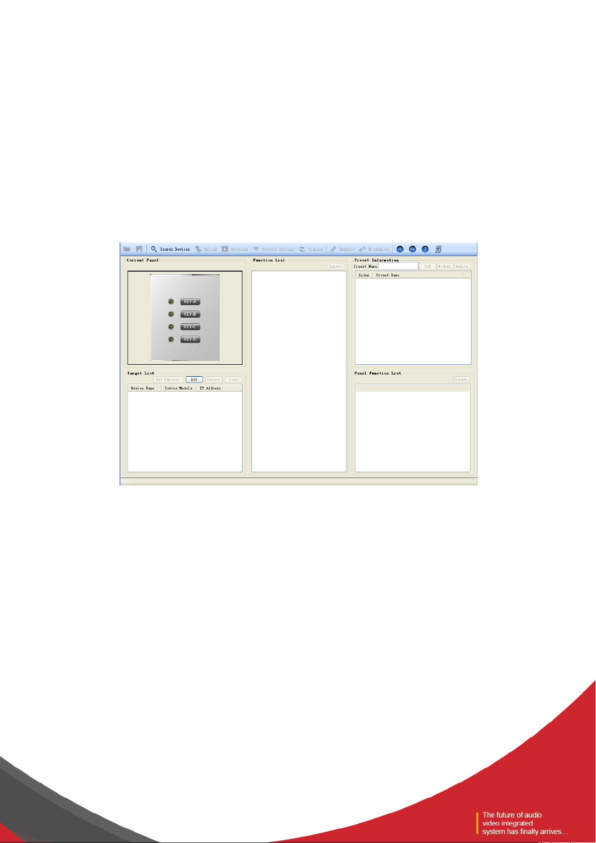
Install the PC software, and select the corresponding software. The start interface is shown in the following
picture:
(1) Menu bar and tool bar: the menu bar contains various function menus of the software, and the tool
bar displays function menus in common use.
(2) Current configuration panel: it displays the currently selected panel or the panel being configured;
(3) List of controlled equipment: it displays the information of current panel and the controlled
equipment;
(4) Function list: it displays the controllable information of the current panel
(5) Preset information: it displays all preset information of the current panel;
(6) List of panel functions: it displays the selected preset sub-information of the current panel.
Page 5
Equipment
installation
Configurate IP
of PC
Login control
software
Seach equipment
Set the panel as current
Modify Panel network information
Down load panel configuration
information
Panel related device setting
Setting panel preset information
Select panel and
matrix
Select needed configuation preset
Configurate panel control key
Select needed configurated control
key
Current Panel
Target list
function list
Preset information
Target list
Toolbar search Setting
Toolbar down load configuration
Toolbar network setting
Modify color
configuration of light
NO
OTHER
PRESET
Upload configuration
Single preset configurated panel
function list
All configuration completed
Panel Configuration Process
All the control key configurated
or not?
YES
All preset configurated or not?
YES
Single panel configuration done
Preset information
panel function list
All panel configurated
or not?
OTHER
PANEL
NO
toolbar upload
configuration
Page 6

2.1 Menu bar and tool bar
(1) Open: To load the equipment configuration saved locally on the currently selected panel. The panel
model must be identical to the saved. Otherwise, it cannot be loaded.
(2) Save: To save the configuration information of the currently selected panel to the local, and then
repeated call with channel opening mode.
(3) Search equipment: To search the panel in the current local area network and the equipment under the
control of the panel, select the equipment to be configured (multiple choices), click "OK", and the
information of selected equipment can be displayed in the controlled list.
(4) Upload configuration: To upload the local configuration information to the panel.
(5) Download configuration: To display the panel configuration on the equipment.
(6) Network settings: To modify the panel's IP and network failure tips.
(7) Panel upgrade: To upgrade the panel.
(8) Run / stop: Conduct simulation debugging on the currently selected panel.
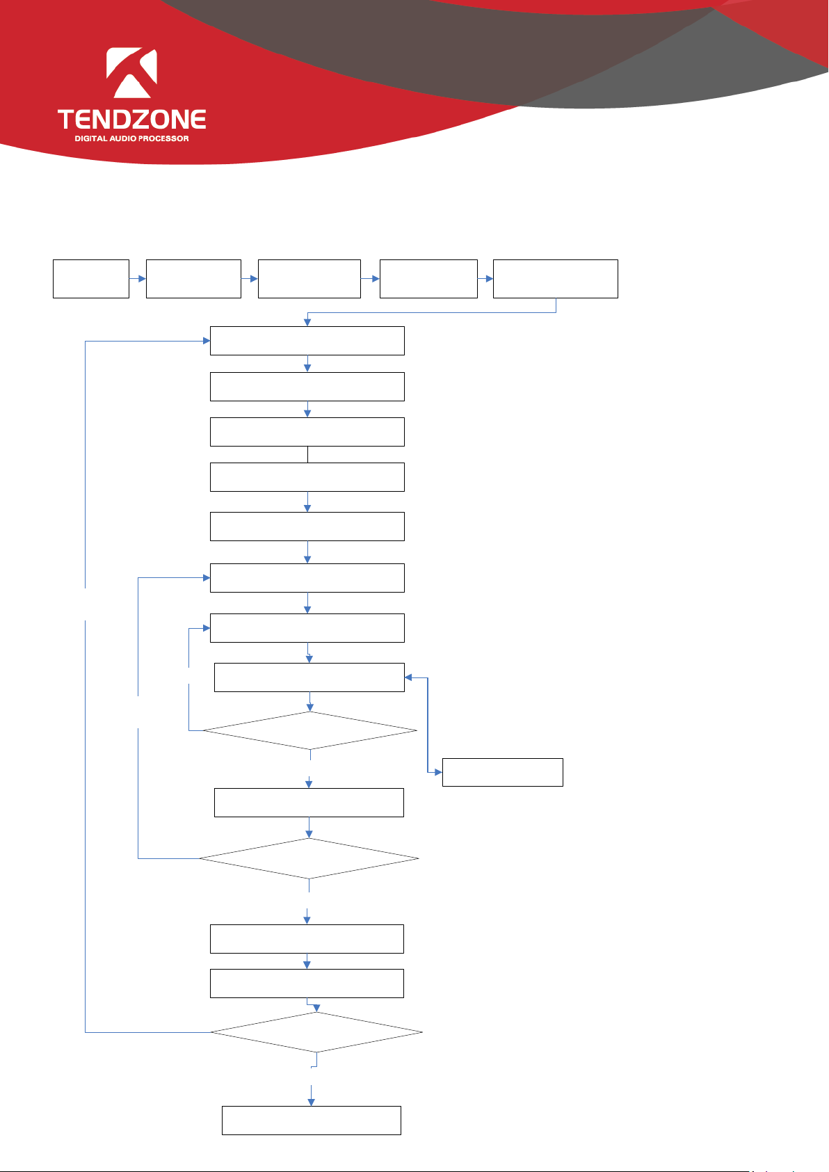
2.2Target List
Click the "Search Devices" on the tool bar:
Click the "Search", to find the current on-line panels and the audio matrix with configurable panel.
Select the panel and audio matrix to be configured, click "Add To List", and the controlled list can display
the selected equipment.
Page 7
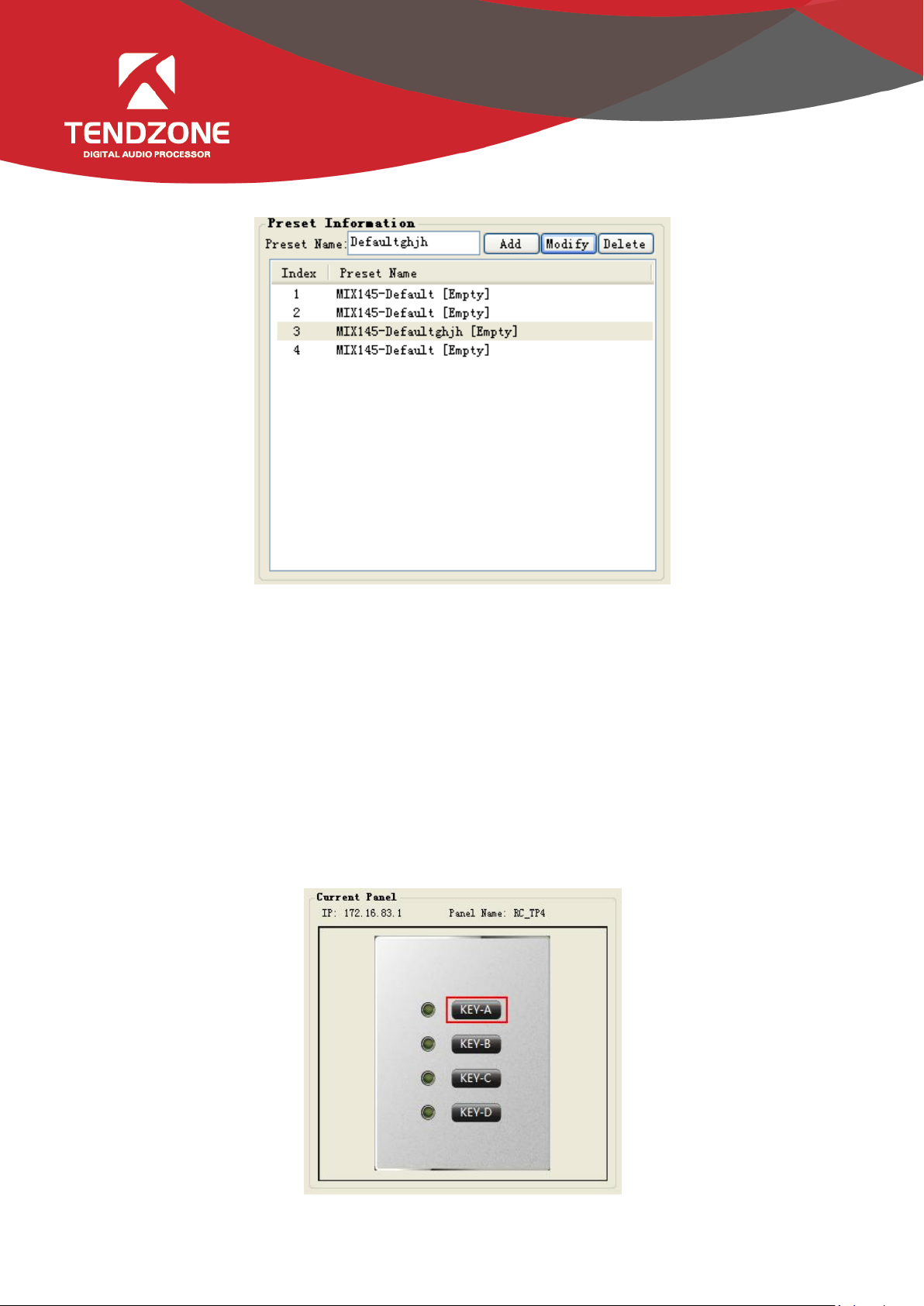
Selected the panel to be configured in the "Target list", click the "Set Current", and the "Current" will
appear at the end of the corresponding equipment name; meanwhile, the "Current Panel" will display the
style of the current panel, and any of the rest interface operations is related with the "current Panel ".
Set Current: To set the selected panel as the current. The upload and download configuration can be
conducted, and the network information and configuration can be modified after the panel is set as the
"current".
Add: To be used for off-line configuration. The user can choose the type of the off-line equipment, as save it
to the local after configuration, which can be opened directly when required.
Delete: to delete the equipment from the current controlled list.
Link: To specify the equipment as the equipment under control of the current panel, and the equipment
will appear in the "function list" automatically after being associated.
Page 8

2.3 Function list
Select the panel in the "Target List" and "Set Current", and then select the equipment under control. Click
the "Link", and the information of the associated equipment will be automatically displayed in the function
list; in case of wrong choice, to select the root directory of corresponding equipment, and click the "Delete"
button.
To expand the structure of the function list, select the minimum level panel node, and double click. The
corresponding function will automatically appear in the "Panel Function List";
If other defaults are required, select other defaults in the "Preset Information", and then configure the
corresponding function in the "Function List".
Page 9
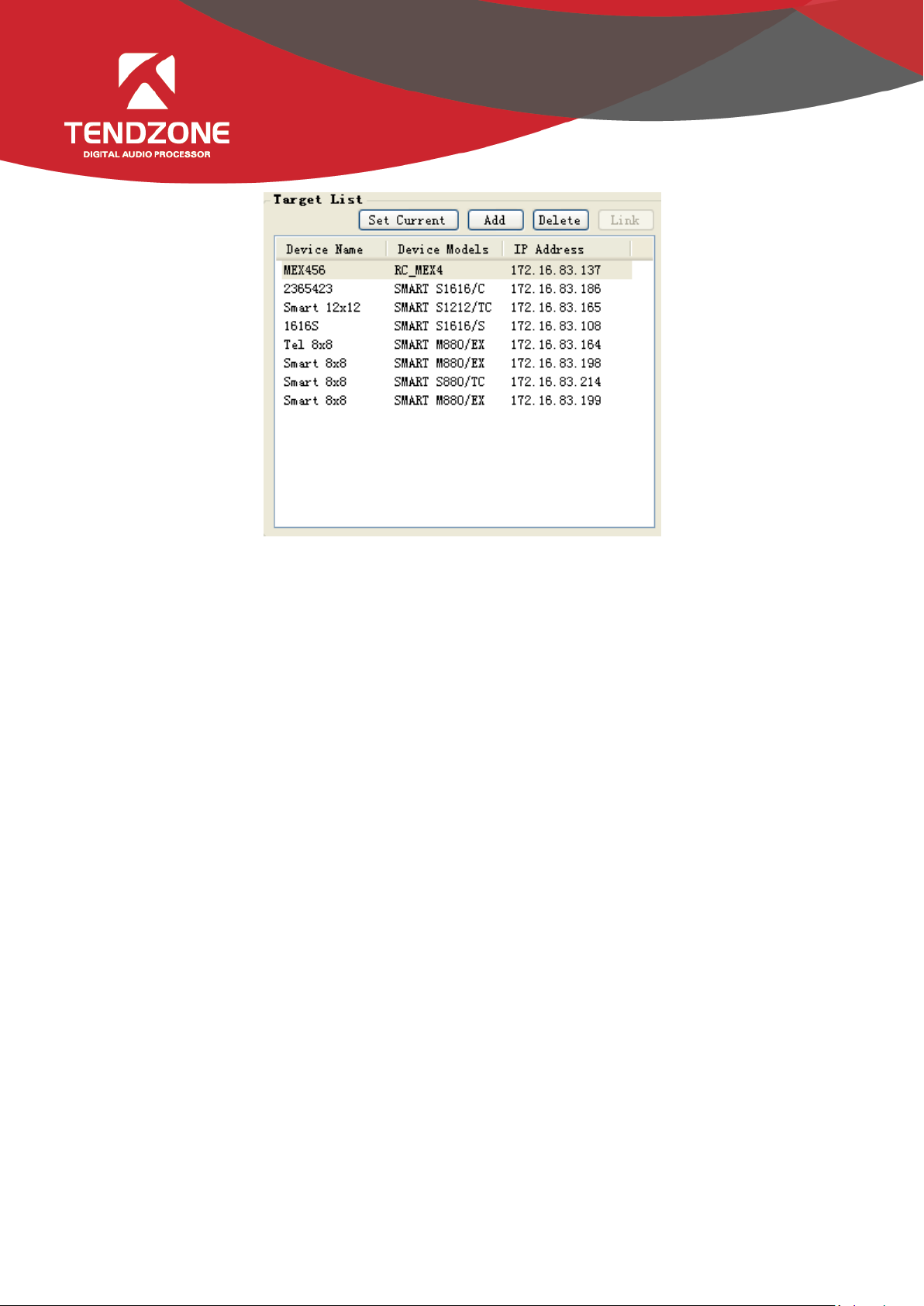
2.4 Preset Information
Each panel can be set to "add" multiple defaults;
To select the default, modify the default name in the edit box, and click "Modify", to save the modified
default name;
After configuring multiple defaults, the redundant defaults can be deleted; the system will perform the
emptying operation for the middle defaults; and the system will perform the deleting operation for the last
default.
After the panel default is set, the control operating configuration can be conducted to each default of the
panel respectively.
2.5 Current configuration panel and the panel function list
After the associated equipment and default information is set, the panel controls can be
configured.
Page 10

Knob and strip
LED lamp
Key LED
lamp
Key
MIC key
Controllable
equipment
Audio matrix
Audio
matrix
Audio matrix, RC
panel
Audio matrix, RC
panel
Controllable
range
Gain and other
numerical range
types
Straight,
mute and
other switch
types
Straight, mute,
panel default and
other switch
types
Function of the
ordinary
programmable
keys + MIC control
Select the key or lamp on the panel, and the information of the equipment under control in the function list
will be filtered in accordance with the control type. The filter type shall be as follows:
Wherein, the key, LED and others are required to be set separately;
If the key controls the default of other panels, there are 2 modes. One is additional, and the other is .
Additional default: to overlay the control functions in the new default, and the previous function shall be
maintained for control not set.
Overlaid default, to empty the panel settings, and then load the new default. The control not set in the new
default shall maintain the ex-factory state.
2.5.1 Key configuration
The following figure is the configuration function after key filtering:
Page 11
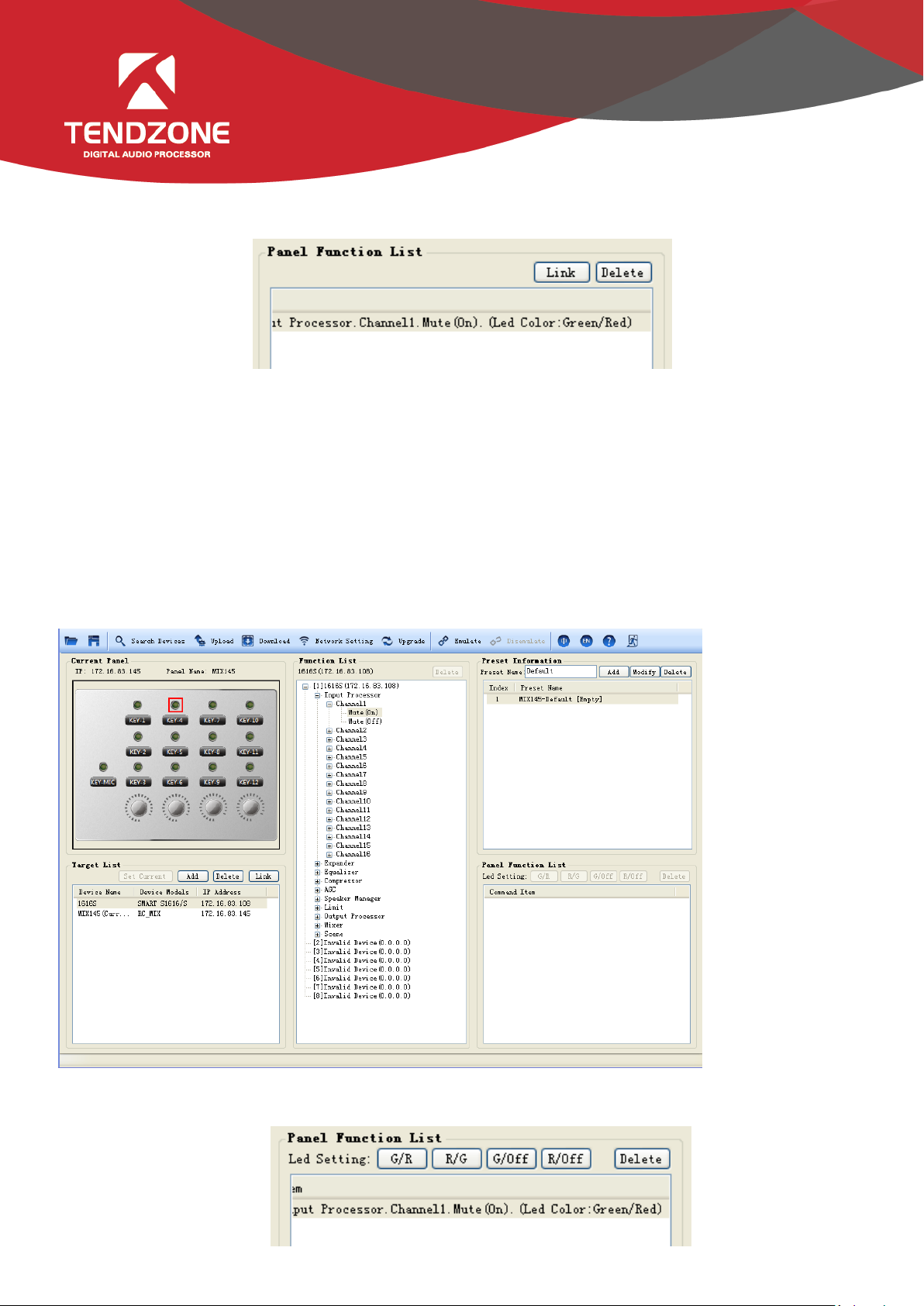
After the key function is configured, click the "Link" in the "Panel Function List", and the corresponding
indicator lamp of the key can configure the related color instructions.
If the configuration of the indicator lamp is to be modified, the corresponding LED shall be selected in the
current configuration panel, to reconfigure the related functions, or just change the color.
2.5.2 Key LED configuration
The default setting of the corresponding indicator lamp of the key can be completed by clicking "Link" in
the "Panel Function List".
If the configuration of the indicator lamp is to be modified, the corresponding LED shall be selected in the
current configuration panel, to reconfigure the related functions, or just change the color.
The following figure is the function after LED filtering:
After the LED configuration is completed, as shown in the following figure, the indicator lamp shows green
when the input channel 1 is in the mute state, and shows red when in the non-mute state.
Page 12

2.5.3 MIC configuration
MIC can only be configured by the corresponding MIC switch:
After associating itself with the corresponding audio matrix by selecting the MIC switch, the function
list is as follows:
To select the microphone setting to choose the corresponding matrix channel, double click the bottom
node, and click the "Link";
Once configured, the sound of the microphone will be input to the first channel of 172.16.83.108. The
green lamp is on when the phantom power is on, and the red lamp is on when the phantom power is off.
Page 13

Note: for PS type panel or MIX type panel, first of all, associate the panel itself and the matrix,
select the key, select the microphone setting in the panel configuration options in the function list, and
then select the corresponding input channel, i.e., input to the matrix channel through the panel.
There are two options for the channel input mode, with phantom power and without phantom
power. With phantom power: open the microphone switch while provide the phantom power.
2.5.4 Knob configuration
Select the knob as shown in the figure. The knob can only control the parameters of gain and
continuous changing numerical range type, and the parameters configured are displayed in the panel
function list.
2.5.5 LED strip lamp
There are two types of strip lamps, one is arc-shaped , and the other is , which can
only display the parameters of gain and continuous changing numerical range type.
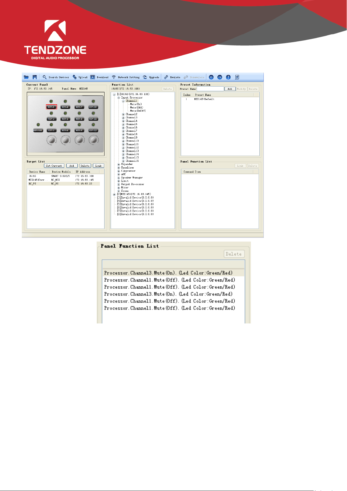
Page 14

Ⅲ、MIX configuration examples
Open the panel PC software, and click the "Search Devices", to search the equipment currently
on-line:
Select the panel and audio matrix to be configured, click "Add to list", and the selected equipment is
displayed in the "Target List ";
Select the panel to be configured, click the "Set Current", and there will appear "Current" at the end of
the equipment name on the panel, indicating the equipment being configured. Meanwhile, click the
"download" in the tool bar, to download the panel configuration to the local.
Then select two equipment in the controlled list, click the "Link", and the corresponding equipment
name and IP address will appear on the function list.
Select the panel key "KEY1", and expand the function list as follows:
Page 15
Expand the sub-options of the matrix in the function list, i.e. function options of the key control.
Double click the sub-option, and the function displays in the "panel function list". Click the "LINK", and
arrange the default lamp colors as follows:
Page 16
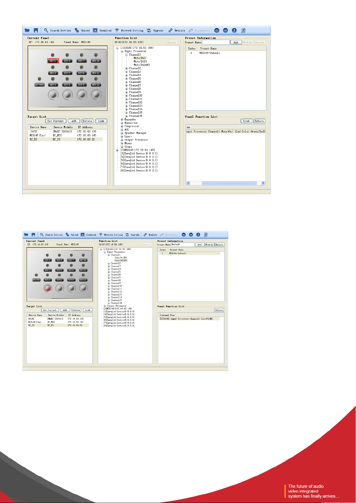
Set the completion key and LED, and the functions in default 1 are as follows:
Then configure the knob, and select the corresponding knob, to configure knob to control the gain of
input channel 1;
Page 17
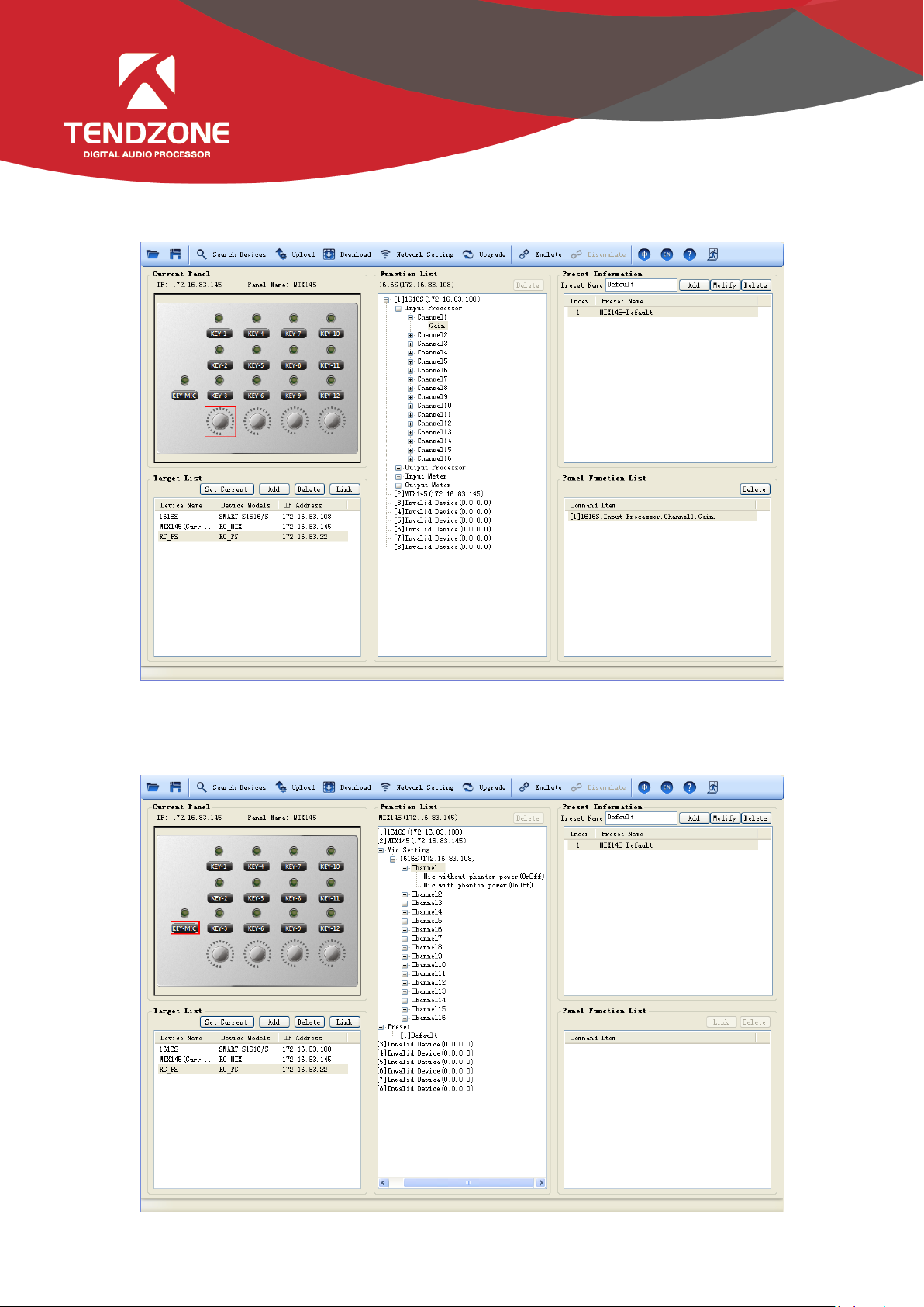
Then configure the corresponding indicator lamp of the knob, select the corresponding indicator lamp,
and configure the electrical level of output channel 1
Then configure the MIC. First of all, associate the current panel and the matrix, select the key, expand
the sub-option of the panel, select the matrix, and specify the input channel. There are two MIC access
modes: with phantom power and without phantom power:
Double click the sub-option to be configured, to complete the configuration. Then click the "upload
Page 18
configuration" in the tool bar, to upload the equipment configuration. The configuration uploaded is
"default 1". If it requires switching to other defaults, the key of this panel or other panels shall be used to
call the default.
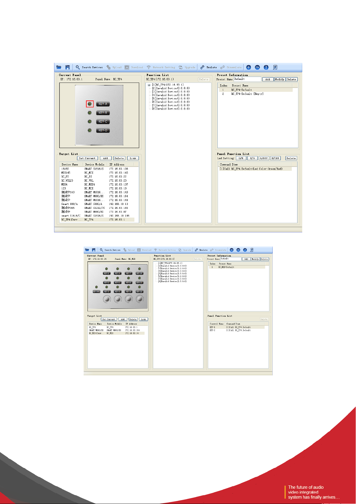
Call default: configure two defaults for Panel 1 (172.16.83.1), and upload the configuration.
Then call the default of Panel 1 through Panel 2 (172.16.83.164):
Page 19

Set Panel 2 (172.16.83.164) as the current configuration panel, and associate Panel 1. Call default 1
through KEY-1 and Call default 2 through KEY-2. In case of additional mode, when the default 2 is called,
the functions of both KEY-1 and KEY-2 are effective in any default.
In case of overwrite model, only KEY-1 function is effective in default 1 and only KEY-2 function is
effective in default 2.
The indicator lamp can only display the current default, and cannot display whether the default model
is additional or overwrite.
After the configuration is completed, click the "upload configuration" in the menu bar options, to
complete the configuration of Panel 2; press KEY1 of Panel 2 to switch Panel 1 to default 1; press KEY2 of
Panel 2 to switch Panel 1 to default 2.
Page 20

IV、Frequently Asked Questions
* What configurations shall be made when the system is used for the first time?
Answer: When this system is used for the first time, the following steps shall be followed:
(1) Read the instructions carefully, especially the safety precautions.
(2) The defaulted IP address in the factory is “192.168.10.10”. If there is no address of
“192.168.10.10” network segment in the PC, please add at least one address of this network segment in
the PC so that the device can be normally connected. The adding process is as follows (the following shows
the process adding IP in XP system):
Right click network computer ->Attribute->Local Connection-> Attribute ->Select Internet
protocol(TCP/IP)in “Series of item used of this connection”,click attribute ->advanced->Click “Add” in the
IP column->Input IP address such as “192.168.10.101”, sub-network mask “255.255.255.0”->Add->OK->OK;
(3) Plug in the POE network cable, for equipment testing: select the "search equipment" in the
system menu, and click the "search" button, to find out whether the equipment can be searched. If the
equipment cannot be searched, please contact us!
* There is no voice from MIC output?
Answer: (1) Check whether the MIC phantom power is correct or not.
(2) Check whether the input configuration of the panel MIC is correct or not.
(3) Check whether the "allow call" in the input source of the audio matrix is turned on or not.
(4) If the above is check without fault, please contact us!
In short, any fault can be report to us in the way of "Help -> Contact Us", to facilitate comprehensive
analysis and facilitate improvements in the future versions
 Loading...