

Page 1

TEMPRIS User Manual
TEMPRIS LAB and TEMPRIS PRO Temperature Measurement Systems
TEMPRIS DataServer Version 7.0 User Guide
Page 2

Page 3

TEMPRIS User Manual
TEMPRIS User Manual
TEMPRIS LAB and TEMPRIS PRO Temperature Measurement Systems
TEMPRIS DataServer Version 7.0 User Guide
Document Version: 7.0.009
Last printing: October 2012
Published by: iQ-mobil solutions GmbH, Holzkirchen, Germany
The information contained in this documentation as well as the products and/or programs
described therein are subject to change without notice and should not be construed as a
commitment by iQ-mobil solutions GmbH.
Although iQ-mobil have gone to great effort to verify the integrity of the information
provided with the TEMPRIS documentation, this documentation could contain technical
inaccuracies or typographical errors. iQ-mobil shall not be liable for errors contained
therein or for incidental consequential damages in connection with the furnishing,
performance or use of this material. iQ-mobil appreciate readers' and/or users'
comments in order to improve this documentation and/or the products described therein.
Changes are periodically made to the information therein. These changes will be
incorporated in new editions of the TEMPRIS documentation.
All rights reserved. No part of the TEMPRIS documentation may be reproduced, stored in
a retrieval system, translated, transcribed or transmitted, in any form or by any means
manual, electric, electronic, electromagnetic, mechanical, chemical, optical or otherwise
without prior express written permission from iQ-mobil solutions GmbH.
TEMPRIS® is a registered trademark of iQ-mobil solutions GmbH. TEMPRIS DataServer™
is a trademark of iQ-mobil solutions GmbH. All other products or services mentioned in
this publication are identified by the trademarks or service marks of their respective
companies or organizations.
Copyright © 2009-2012 iQ-mobil solutions GmbH.
All Rights Reserved.
Publication Notes Page 3 of 80
Page 4

TEMPRIS User Manual
Contents
1 Important Information ................................................................................. 7
1.1 Using this Documentation ..................................................................................... 7
Compilation and Publication Notice ......................................................................... 7
Organization of this Documentation ........................................................................ 7
Illustrations ......................................................................................................... 8
Copyright ............................................................................................................ 8
Trademarks ......................................................................................................... 8
1.2 Symbols and Conventions ..................................................................................... 9
Terms and Notations ............................................................................................ 9
Acronyms ............................................................................................................ 9
Symbolic Conventions.......................................................................................... 10
Safety Symbols ................................................................................................... 11
1.3 Intended Use ...................................................................................................... 12
1.4 Operators and Users ............................................................................................ 12
1.5 Operator Obligations ........................................................................................... 12
1.6 User Obligations ................................................................................................. 12
1.7 Safety Instructions .............................................................................................. 13
1.7.1 Important Safety Instructions .................................................................... 13
1.7.2 CE Compliance ......................................................................................... 15
1.7.3 United States FCC Compliance ................................................................... 16
1.7.4 Industry Canada (IC) Compliance .............................................................. 17
1.8 Related Documentation ........................................................................................ 18
1.9 Addresses .......................................................................................................... 18
2 Introduction ............................................................................................... 19
2.1 TEMPRIS - Wireless Temperature Monitoring without Batteries ................................. 19
2.2 TEMPRIS Operational Principle .............................................................................. 20
2.3 TEMPRIS Applications .......................................................................................... 21
3 TEMPRIS System Setup .............................................................................. 23
3.1 TEMPRIS System Components .............................................................................. 23
3.2 Required Cable Connections ................................................................................. 25
3.2.1 TEMPRIS PRO Connections and Interfaces ................................................... 25
3.2.2 TEMPRIS LAB Connections and Interfaces ................................................... 28
3.3 TEMPRIS DataServer Installation .......................................................................... 31
3.3.1 TEMPRIS DataServer System Requirements ................................................ 31
3.3.2 New Installation ....................................................................................... 32
3.3.3 Update Installation ................................................................................... 32
4 TEMPRIS DataServer User Interface and Function Reference ..................... 33
4.1 TEMPRIS DataServer Features .............................................................................. 34
4.2 Program Start ..................................................................................................... 35
4.1.1 TEMPRIS LAB Start-up Screen ................................................................... 35
4.1.2 TEMPRIS PRO Start-up Screen ................................................................... 36
4.3 Status Bar .......................................................................................................... 37
4.4 Interface Configuration ........................................................................................ 38
4.5 Establishing the Data Connection between PC and TEMPRIS Interrogation Unit ........... 39
4.6 Config View ........................................................................................................ 41
4.6.1 Config View - General ............................................................................... 42
4.6.2 Config View - Channel / Antenna Configuration ............................................ 45
4.6.3 Config View - Measurement ....................................................................... 51
4.7 Text View ........................................................................................................... 52
4.8 Graphics View ..................................................................................................... 55
4.9 Signal View ........................................................................................................ 65
4.10 Clearing the Current Data Screen .......................................................................... 67
4.11 Recording Incoming Measuring Data onto Log Files ................................................. 67
4.12 Print and Plot Output ........................................................................................... 70
4.13 Loading Log Files for Offline Data Visualization ....................................................... 71
4.14 Data Export to CSV ............................................................................................. 73
4.15 Copying Screens to the Windows Clipboard ............................................................ 75
4.16 Retrieving the Current Configuration Settings ......................................................... 76
4.17 Exiting the TEMPRIS DataServer ........................................................................... 76
Contents Page 4 of 80
Page 5

TEMPRIS User Manual
5 TEMPRIS Options ........................................................................................ 77
5.1 Modbus TCP/IP Interface ...................................................................................... 77
5.1.1 TEMPRIS Modbus TCP/IP Interface Setup .................................................... 78
5.1.2 TEMPRIS Modbus TCP/IP Channel Configuration ........................................... 79
Tables
Table 3-1: TEMPRIS DataServer System Requirements ..................................................... 31
Table 4-1: TEMPRIS DataServer Status Bar Elements ....................................................... 37
Figures
Figure 3-1: TEMPRIS Configuration with Single Antenna ................................................... 23
Figure 3-2: TEMPRIS Configuration with Multiple Antennas ............................................... 24
Figure 3-3: TEMPRIS PRO Connections with Labels........................................................... 25
Figure 3-4: TEMPRIS PRO Antenna Connection A1 ........................................................... 26
Figure 3-5: Torque Wrench ........................................................................................... 26
Figure 3-6: TEMPRIS PRO Antenna Multiplexer Connection X ............................................. 27
Figure 3-7: TEMPRIS LAB Connections and Interfaces ...................................................... 28
Figure 3-8: TEMPRIS LAB Antenna Connection A1 ............................................................ 29
Figure 3-9: TEMPRIS LAB Virtual Keyboard ..................................................................... 29
Figure 4-1: TEMPRIS LAB Start-up Screen ...................................................................... 35
Figure 4-2: TEMPRIS PRO Start-up Screen ...................................................................... 36
Figure 4-3: TDS Status Bar Elements ............................................................................. 37
Figure 4-4: TDS Options - Connection ............................................................................ 38
Figure 4-5: TDS Toolbar - Stop Logging .......................................................................... 39
Figure 4-6: TDS Toolbar – Stop Measure ........................................................................ 39
Figure 4-7: TDS File – Connect Submenu ........................................................................ 39
Figure 4-8: TDS Status Bar – Connect Indicators ............................................................. 40
Figure 4-9: TDS Status Bar – Receive Data Indicators ...................................................... 40
Figure 4-10: TDS Config View ....................................................................................... 41
Figure 4-11: TDS Config View - General ......................................................................... 42
Figure 4-12: TDS Config View – General – Select Config ................................................... 43
Figure 4-13: TDS Config View – General – Save Config .................................................... 44
Figure 4-14: TDS Config View – Channel / Antenna Configuration ...................................... 45
Figure 4-15: TDS Config View – Channel / Antenna Configuration – Active Channels ............ 45
Figure 4-16: TDS Config View – Channel / Antenna Configuration – Channel Setup .............. 46
Figure 4-17: TDS Config View – Channel / Antenna Configuration – Channel Tooltips ........... 47
Figure 4-18: TDS Config View – Channel / Antenna Configuration – Channel Settings .......... 48
Figure 4-19: TDS Config View – Channel / Antenna Configuration – Change Sensor ............. 49
Figure 4-20: TDS Config View – Channel / Antenna Configuration – Channel Properties ........ 50
Figure 4-21: TDS Config View - Measurement ................................................................. 51
Figure 4-22: TDS Text View .......................................................................................... 52
Figure 4-23: TDS Text View – Fahrenheit Temperature Display ......................................... 54
Figure 4-24: TDS Graphics View .................................................................................... 55
Figure 4-25: TDS Graphics View – Channel Toolbar .......................................................... 56
Figure 4-26: TDS Graphics View – Channel Buttons ......................................................... 56
Figure 4-27: TDS Graphics View – Channel Button Context Menu ....................................... 56
Figure 4-28: TDS Graphics View – Channel Display Settings .............................................. 57
Figure 4-29: TDS Graphics View – Show All Data ............................................................. 58
Figure 4-30: TDS Graphics View – Marker Function .......................................................... 59
Figure 4-31: TDS Graphics View – Zoom Window Selection ............................................... 60
Figure 4-32: TDS Graphics View – Zoom Window Display ................................................. 60
Figure 4-33: TDS Graphics View – Time Label Settings ..................................................... 61
Figure 4-34: TDS Graphics View – Temperature Label Settings .......................................... 62
Figure 4-35: TDS Graphics View – Graphics Area Context Menu ......................................... 63
Figure 4-36: TDS Graphics View – Show Second Trace S/N ............................................... 64
Figure 4-37: TDS Signal View – Signal Strength .............................................................. 65
Figure 4-38: TDS Signal View – Antenna Matching ........................................................... 66
Figure 4-39: Start Logging - Log File Name Selection ....................................................... 67
Figure 4-40: Start Logging – Log File Info ....................................................................... 68
Figure 4-41: Save Current Data ..................................................................................... 69
Figure 4-42: Print Page Setup ....................................................................................... 70
Figure 4-43: Loaded Log File Info .................................................................................. 71
Contents Page 5 of 80
Page 6

TEMPRIS User Manual
Figure 4-44: Loaded Log File Info - Data ......................................................................... 72
Figure 4-45: TEMPRIS CSV Data in Microsoft Excel........................................................... 73
Figure 4-46: Copy Screen to Clipboard ........................................................................... 75
Figure 4-47: Current Configuration Settings .................................................................... 76
Figure 5-1: TEMPRIS Modbus TCP/IP to PLC Interface Setup ............................................. 77
Figure 5-2: TEMPRIS Sensor Data and Sensor Status Output to PLC ................................... 77
Figure 5-3: TEMPRIS DataServer Config – System – Automation ....................................... 78
Figure 5-4: TEMPRIS DataServer Channel Properties - Automation .................................... 80
Contents Page 6 of 80
Page 7

TEMPRIS User Manual
Chapter 1
provides important information about this documentation and the products
described therein.
Chapter 2
provides general information about wireless temperature monitoring with
TEMPRIS, the TEMPRIS operational principle and TEMPRIS applications.
Chapter 3
provides details about the interfaces and connections of the TEMPRIS LAB
and contains information about how to set up
these systems and how to install the TEMPRIS DataServer software.
Chapter 4
describes the user interface and the functions of the TEMPRIS DataServer
TEMPRIS
DataServer software.
Chapter 5
describes optional TEMPRIS features and how to use them.
1 Important Information
This documentation is part of the TEMPRIS system. It describes how to use the TEMPRIS
system and the TEMPRIS DataServer software. Please read this documentation carefully
before using the TEMPRIS system.
The TEMPRIS system may only be used by persons who have been appropriately trained.
1.1 Using this Documentation
Compilation and Publication Notice
This documentation has been compiled and published by iQ-mobil solutions GmbH. It
covers the latest product descriptions and technical specifications. iQ-mobil solutions
GmbH reserves the right to make changes without notice to this documentation and the
specifications of the products described in this documentation. iQ-mobil solutions GmbH
shall not be responsible for any damages (including consequential) caused by reliance on
the materials presented, including but not limited to typographical and other errors
relating to this documentation.
Organization of this Documentation
and TEMPRIS PRO systems
software and provides detailed information about how to use the
Important Information Page 7 of 80
Page 8

TEMPRIS User Manual
Illustrations
The images used in the TEMPRIS documentation (photos, screenshots, etc.) may differ
from the original as long as the correct description of the illustrated functions is not
affected.
Copyright
All rights reserved. No part of the TEMPRIS documentation may be reproduced, stored in
a retrieval system, translated, transcribed or transmitted, in any form or by any means
manual, electric, electronic, electromagnetic, mechanical, chemical, optical or otherwise
without prior express written permission from iQ-mobil solutions GmbH.
Trademarks
TEMPRIS® is a registered trademark of iQ-mobil solutions GmbH. TEMPRIS DataServer™
is a trademark of iQ-mobil solutions GmbH. All other products or services mentioned in
this publication are identified by the trademarks or service marks of their respective
companies or organizations.
Important Information Page 8 of 80
Page 9

TEMPRIS User Manual
Menu Bar
Horizontal pull-down menu function bar at the top of the TEMPRIS
DataServer screen.
Function Tab
Tab controls under the Menu Bar for switching between different views
in the centered of the TEMPRIS DataServer screen.
Status Bar
Horizontal bar with status message and indicator controls at the bottom
of the TEMPRIS DataServer screen.
Toolbar
Horizontal bar above the Status Bar with large touch-screen command
buttons for frequently used commands and/or functions.
Config View
Center screen area for displaying and setting configuration parameters.
Text View
Center screen area for displaying incoming TEMPRIS measuring data
using temperature value text controls.
Graphics View
Center screen area for displaying incoming TEMPRIS measuring data
using graphic plots.
Signal View
Center screen area for displaying radio signal quality and antenna
system.
TLAB
Type/model name for TEMPRIS LAB, the laboratory version of the
TEMPRIS systems.
TIRU
Type/model name for TEMPRIS IRU-2, the TEMPRIS interrogation unit.
IRU
Acronym for InterRogation Unit of the TEMPRIS system.
TDS
Acronym for TEMPRIS DataServer, the Windows software for
logging, archiving and visualizing TEMPRIS measuring data.
1.2 Symbols and Conventions
Terms and Notations
The following terms and notations are used throughout the TEMPRIS documentation:
assignment information during for the currently connected TEMPRIS
Acronyms
The following acronyms are used throughout the TEMPRIS documentation:
communicating with TEMPRIS interrogation units and for monitoring,
Important Information Page 9 of 80
Page 10
TEMPRIS User Manual
Lineprint
Lineprint font represents text output generated by the system.
Boldface
Boldfaced words or characters in format or command descriptions
mmands or
keywords to be inserted directly.
Emphasize
Emphasized text is used for optical accentuation.
" "
Double quotes denote names and/or path names or enclose characters
and/or character sequences directly to be inserted.
[ ]
Square brackets enclose optional items in format or command
descriptions or physical unit designators in normal text.
{ }
Braces enclose a list of items in format or command description, from
which one has to be chosen.
|
A vertical bar separates items in a list of choices.
< >
Angle brackets enclose the logical name of a key on the keyboard. In
format or command descriptions, angle brackets enclose values to be
supplied.
>
Boldfaced greater signs in line print font are used for denoting prompts
on operating system level.
...
Horizontal ellipsis points indicate either optional repetition of the
irrelevant parts of a figure or example.
:
Vertical ellipsis points indicate absence of irrelevant parts of a figure,
an example or a format or command description.
a b ...
Keyboard (input) - standard key(s)
F1 F2 ...
Keyboard (input) - function key(s)
filename
File or directory path name.
keyword
Topic definitions or syntactic terminals, i.e., commands or keywords to
be inserted directly.
message
TEMPRIS DataServer / system status or error message display.
Menu
TEMPRIS DataServer function menu.
Menu Function
TEMPRIS DataServer menu function.
Menu Option
TEMPRIS DataServer menu option.
Button
TEMPRIS DataServer dialog button.
Symbolic Conventions
The following symbolic conventions are used throughout the TEMPRIS documentation:
represent topic definitions or syntactic terminals, i.e., co
preceding element in format or command descriptions or absence of
The character sequences mentioned above may regain original meaning when used in
programming languages, interpreter languages, specification languages, syntax
description languages, etc.
Important Information Page 10 of 80
Page 11

TEMPRIS User Manual
Safety Symbols
Important Information Page 11 of 80
Page 12

TEMPRIS User Manual
1.3 Intended Use
TEMPRIS is a wireless and battery-free temperature measurement system for measuring
the product temperature in pharmaceutical lyophilization processes. TEMPRIS
measurement data can be used for lyo-cycle development and optimization, hot and cold
spot detection, lyo-cycle scale-up and lyo-cycle transfer.
Notes
Functions or applications not listed in the range are excluded of the intended use.
Modifications of the TEMPRIS products which are possible to be done by a skilled person
leading to additional or modified functions or applications are excluded of the intended
use.
1.4 Operators and Users
The TEMPRIS system may only be installed, operated and used by persons who have the
necessary training or knowledge and experience to do so.
TEMPRIS system fittings, extensions, adjustments, modifications or repairs may only be
carried out by the manufacturer or personnel authorized by the manufacturer.
The TEMPRIS user should be familiar with the use of his Windows operating system in a
network environment. A basic understanding of wireless data transmission technology is
beneficial.
1.5 Operator Obligations
The operator of TEMPRIS system is responsible for ensuring that
• national or local regulations for installation, operation, use and maintenance
are met,
• the accident prevention regulations are complied with,
• the TEMPRIS system is in a proper and safe condition,
• the TEMPRIS documentation required for the operation of the system is readily
accessible at all times.
1.6 User Obligations
When entering parameters, note the following:
• The input parameters must be verified by the user, i.e., the user must verify
the correctness of the entered values.
• If during this test deviations between the desired and/or required values and
values displayed on the unit can be found, then the setting must be corrected
before the function is activated.
• The actual values must be compared with predetermined target values.
Important Information Page 12 of 80
Page 13

TEMPRIS User Manual
1.7 Safety Instructions
1.7.1 Important Safety Instructions
• Read these instructions.
• Keep these instructions.
• Heed all warnings.
• Follow all instructions.
• The TEMPRIS system must be installed by iQ-mobil solutions GmbH. The
TEMPRIS system installation must be formally accepted by the customer.
• Formally accepted TEMPRIS installations must not be modified by the customer.
• Do not use the TEMPRIS system if the security is no longer guaranteed due to
damage.
• Do not use the TEMPRIS system near water or if any of its components are
damp or wet.
• The TEMPRIS system cables must be wired in such a way as to avoid any safety
hazards. Legally required workplace precautions must be followed.
• Do not touch the power cable of the TEMPRIS system with damp or wet hands.
• Do not block any ventilation openings or cooling fins of any of the TEMPRIS
components. The installation and fitting instructions must be followed.
• The operating temperature for the TIRU, TLAB, HF-MUX and Outbox
components ranges from 0 °C to +35 °C. Do not install or place these
components near any heat sources such as radiators, heat registers, stoves, or
apparatus that produce heat. Protect these components from direct sunlight.
• Only use attachments/accessories specified by iQ-mobil solutions GmbH.
• Uninterrupted Power Systems (UPS) are recommended if TEMPRIS is used in
productive environments.
• All TEMPRIS components except for TIRU, TLAB and HF-MUX must be cleaned
and sterilized before being used in a productive lyophilization system
(appropriate procedures: steam sterilization up to 135 ° C, 1% ETO solution).
• TEMPRIS temperature sensors must be replaced after a maximum of 20
sterilization cycles.
• Refer all servicing to qualified service personnel authorized by iQ-mobil
solutions GmbH. Servicing is required when the apparatus has been damaged
in any way, such as power-supply cord or plug is damaged, liquid has been
spilled or objects have fallen into the apparatus, the apparatus has been
exposed to rain or moisture, does not operate normally, or has been dropped.
Power Source Warning
Labels on the TEMPRIS components indicate the correct power source. Operate the
components only from electrical outlets with the voltage and frequency indicated on the
labels. If you are uncertain of the type of your power supply, consult your service
provider or your local power company.
The AC inlets on the TEMPRIS unit must remain accessible and operable at all times.
Important Information Page 13 of 80
Page 14

TEMPRIS User Manual
Commissioning Requirements
The TEMPRIS system must be in perfect condition. The TEMPRIS system must not be put
in operation if any of its components are mechanically damaged. Damaged components
must be replaced.
Repair
The installation of the TEMPRIS system and extensions, adjustments, alterations or
repairs to the TEMPRIS system may only be performed by the manufacturer or persons
authorized by him.
Important Information Page 14 of 80
Page 15
TEMPRIS User Manual
Deutsch
[German]
Dieses Gerät entspricht den grundlegenden Anforderungen und den
weiteren entsprechenden Vorgaben der Richtlinie 1999/5/EU.
English
This equipment is in compliance with the essential requirements and other
relevant provisions of Directive 1999/5/EC.
1.7.2 CE Compliance
Declaration of Conformity with Regard to the EU Directive 1999/5/EC (R&TTE Directive)
This declaration is only valid for configurations (combinations of software, firmware and
hardware) supported or provided by iQ-mobil solutions GmbH for use within the EU. The
use of software or firmware not supported or provided by iQ-mobil solutions GmbH may
result in the equipment no longer being compliant with the regulatory requirements.
Note: The full declaration of conformity for this product is available from iQ-mobil
solutions GmbH.
The following standards were applied during the assessment of the product against the
requirements of the Directive 1999/5/EC:
• Radio: ETSI EN 300 328, EN 62311, 1999/519/EC
• EMC: EN 61000-6-2, EN 61000-6-4, EN 301 489-1, EN 301 489-17
• Safety: EN 60950-1
The CE mark and class-2 identifier are affixed to the product and its packaging. This
product conforms to the following European directives:
-1999/5/EC
National Restrictions
This product is for indoor use only.
Note: The regulatory limits for maximum output power are specified in EIRP. The EIRP
level of a device can be calculated by adding the gain of the antenna used (specified in
dBi) to the output power available at the connector (specified in dBm).
Antennas
Use only the antenna(s) supplied with the product.
Important Information Page 15 of 80
Page 16

TEMPRIS User Manual
1.7.3 United States FCC Compliance
FCC Declaration of Conformity
This device complies with Part 15 of the FCC Rules. Operation is subject to the following
two conditions: 1) this device may not cause harmful interference, and 2) this device
must accept any interference received, including interference that may cause undesired
operation.
Caution: Changes or modifications not expressly approved by the party responsible for
compliance could void the user's authority to operate the equipment.
Note: This equipment has been tested and found to comply with the limits for a Class A
digital device, pursuant to part 15 of the FCC Rules. These limits are designed to provide
reasonable protection against harmful interference when the equipment is operated in a
commercial environment. This equipment generates, uses, and can radiate radio
frequency energy and, if not installed and used in accordance with the instruction
manual, may cause harmful interference to radio communications. Operation of this
equipment in a residential area is likely to cause harmful interference in which case the
user will be required to correct the interference at his own expense.
Note: This equipment complies with FCC radiation exposure limits set forth for an
uncontrolled environment. This equipment should be installed and operated with
minimum distance 20 cm between the radiator and your body.
This transmitter must not be co-located or operating in conjunction with any
other antenna or transmitter.
Important Information Page 16 of 80
Page 17

TEMPRIS User Manual
1.7.4 Industry Canada (IC) Compliance
Industry Canada (IC) Compliance Statement
This device complies with Industry Canada licence-exempt RSS standard(s). Operation is
subject to the following two conditions: (1) this device may not cause interference, and
(2) this device must accept any interference, including interference that may cause
undesired operation of the device.
Under Industry Canada regulations, this radio transmitter may only operate using an
antenna of a type and maximum (or lesser) gain approved for the transmitter by
Industry Canada. To reduce potential radio interference to other users, the antenna type
and its gain should be so chosen that the equivalent isotropically radiated power (e.i.r.p.)
is not more than that necessary for successful communication.
Industrie Canada (IC) Déclaration de conformité
Le présent appareil est conforme aux CNR d'Industrie Canada applicables aux appareils
radio exempts de licence. L'exploitation est autorisée aux deux conditions suivantes : (1)
l'appareil ne doit pas produire de brouillage, et (2) l'utilisateur de l'appareil doit accepter
tout brouillage radioélectrique subi, même si le brouillage est susceptible d'en
compromettre le fonctionnement.
Conformément à la réglementation d'Industrie Canada, le présent émetteur radio peut
fonctionner avec une antenne d'un type et d'un gain maximal (ou inférieur) approuvé
pour l'émetteur par Industrie Canada. Dans le but de réduire les risques de brouillage
radioélectrique à l'intention des autres utilisateurs, il faut choisir le type d'antenne et son
gain de sorte que la puissance isotrope rayonnée équivalente (p.i.r.e.) ne dépasse pas
l'intensité nécessaire à l'établissement d'une communication satisfaisante.
Industry Canada (IC) Radiation Exposure Statement
This equipment complies with IC RSS-102 radiation exposure limits set forth for an
uncontrolled environment. This equipment should be installed and operated with
minimum distance 20cm between the radiator and your body.
Industrie Canada (IC) Déclaration d'exposition aux radiations
Cet équipement est conforme aux limites d'exposition aux rayonnements IC établies pour
un environnement non contrôlé. Cetéquipement doit être installé et utilisé avec un
minimum de 20 cm de distance entre la source de rayonnement et votre corps.
Important Information Page 17 of 80
Page 18

TEMPRIS User Manual
1.8 Related Documentation
As TEMPRIS customer you will receive project-specific TEMPRIS documentation such as
specific installation guides and user manuals, SOP’s, IQ/OQ documentation, etc. as per
your requirements and/or according to agreements with us. Please contact TEMPRIS
support if you have any queries in relation to project-specific TEMPRIS documentation.
Check the iQ-mobil Website at www.iqmobil.com for our contact details.
1.9 Addresses
We appreciate comments from the people who are using the TEMPRIS system, and we
are particularly thankful for suggestions on how to improve the TEMPRIS system and/or
the TEMPRIS DataServer software by introducing new or improving existing features and
functions. If you have questions or problems related to the use of TEMPRIS, please
contact:
iQ-mobil solutions GmbH
Industriestrasse 7
83607 Holzkirchen
Germany
Phone... : +49-(0)8024-47447 0
Fax ...... : +49-(0)8024-47447 10
E-Mail .. : [email protected]
Web ..... : www.iqmobil.com
Important Information Page 18 of 80
Page 19

TEMPRIS User Manual
2 Introduction
2.1 TEMPRIS - Wireless Temperature Monitoring without Batteries
Temperature is an important physical parameter measured in many scientific and
technical fields such as chemistry, pharmacology, medicine, physics, electronics,
mechanical engineering, etc. In many cases, it is particularly important to measure and
record temperature
• as accurately as possible,
• as genuinely as possible,
• as reproducible as possible,
• as immediate as possible (real-time, online),
• in the widest possible measurement range,
• through long periods of time.
Frequently, these objectives are only partially achieved.
This is due to the use of conventional temperature sensors (thermometer, thermo
elements, thermo resistors, etc.), which tend to falsify and delay (sensor response versus
time hysteresis) measurement results because of
• the sensor’s thermal capacity (thermal mass),
• the electrical energy required for sensor operation,
• heat transmission / thermal conduction through power and/or data cables.
These problems were and still are commonly tackled by either using “local data loggers”
or by deploying battery-powered (radio) data transmission facilities to avoid troubleprone cables. However, these methods cause a significant if not inadmissible thermal
capacity increase in the measurement set-up with the aforementioned undesired
consequences. Batteries frequently prove to be inadequate, undesirable, or even
forbidden in specific measurement environments
The real-time availability of measuring data (e.g. for process control purposes) usually is
another important aspect of the application. The use of wired sensors is particularly
costly in environments with moving measurement objects and devices (translatory or
rotatory motion; e.g. assembly lines, centrifuges, shafts, bearings, etc.). Not only are
wired sensors difficult and costly to install in such environments (trailing cables, slip
rings, etc.), they inflict further disadvantages when in operation (susceptibility to
interference, high maintenance costs, etc.).
An “ideal” temperature measurement system should include the following features:
• wireless (without cable supply)
• battery-free (no need for integrated energy / power supply)
TEMPRIS (Temperature Remote Interrogation System) by iQ–mobil solutions GmbH is
such a system. TEMPRIS works wirelessly and without batteries.
Introduction Page 19 of 80
Page 20

TEMPRIS User Manual
2.2 TEMPRIS Operational Principle
The TEMPRIS system is used for wireless temperature measurement and monitoring of
up to 16 sensors without batteries. Radio wave transmission is used to supply the
sensors with power and to query the sensor measurement data.
The TEMPRIS temperature sensors work on the principle of temperature-regulated
resonators, i.e. small electrical circuits with special quartz crystals which are oscillated by
an external electromagnetic field (carrier frequency 2.4 GHz, modulation frequencies
approx. 10 MHz).
A temperature sensor query cycle starts with a receiving channel detection phase,
followed by an excitation with a modulated signal. The excitation signal is demodulated
by the receiving sensor, and the energy from this signal is preserved as oscillation
energy by the sensor. The preserved sensor oscillation energy is then used to modulate
the carrier frequency sent by the interrogation unit and to transmit the modulated signal
back through the sensor antenna. The TEMPRIS interrogation unit receives this
“backscatter” signal, converts it into digital data and calculates the temperature value
contained in this data. The calculated temperature is transmitted via LAN connection to
the TEMPRIS DataServer software on the connected PC where the temperature data is
logged and visualized.
The TEMPRIS system is available in different configurations. Aside from a set of up to 16
wireless temperature sensors, each TEMPRIS system comes with an interrogation unit
with either a single antenna for simultaneous transmit and receive operation or a
multiplexer switch for operating up to 6 antennas simultaneously.
Introduction Page 20 of 80
Page 21

TEMPRIS User Manual
2.3 TEMPRIS Applications
TEMPRIS is especially suitable where the following requirements have to be met:
• wireless data transmission (measurement object in translatory or rotatory
motion)
• battery-free data transmission (energy-saving, environment-friendly, low heat
capacity)
• reproducible high precision of data measurement
• “real-time” data availability
TEMPRIS is available for a range of applications:
• Chemistry, Pharmacology, Medicine:
• Reactors
• Rotary mixers
• Freeze dryers
• Sterilizers
• Medical monitoring
• Handling of toxically / radioactive substances
• Industrial Plants:
• Paper mills (calenders, etc.)
• Transmissions
• Anti-friction bearings
• Flow furnaces
• Engine development
• Measurement of temperature distributions and gradients
• High voltage overhead lines, transformer stations
Introduction Page 21 of 80
Page 22

Page 23
TEMPRIS User Manual
3 TEMPRIS System Setup
3.1 TEMPRIS System Components
A typical TEMPRIS measurement system consists (at least) of the following system
components:
• Interrogation Unit IRU-2 (PRO or LAB)
• External power supply
• HF Antenna(s)
• HF Antenna Cable
• up to 16 Sensors
• TEMPRIS DataServer software (recommended, but not required in case of
direct control of the plant through PLC)
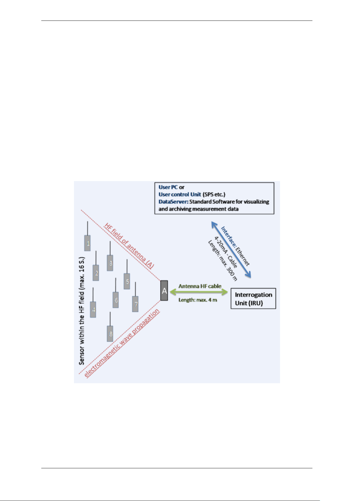
The following block diagram shows the TEMPRIS configuration with a single antenna.
Figure 3-1: TEMPRIS Configuration with Single Antenna
TEMPRIS System Setup Page 23 of 80
Page 24
TEMPRIS User Manual
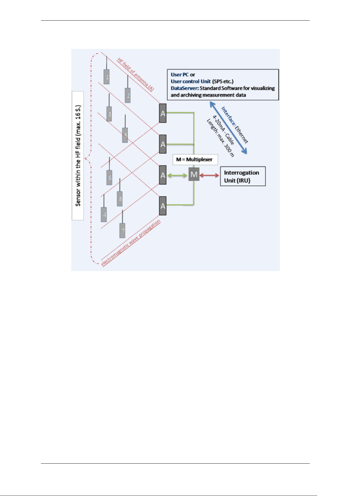
The following block diagram shows the TEMPRIS configuration with multiple antennas.
Figure 3-2: TEMPRIS Configuration with Multiple Antennas
TEMPRIS System Setup Page 24 of 80
Page 25
TEMPRIS User Manual
3.2 Required Cable Connections
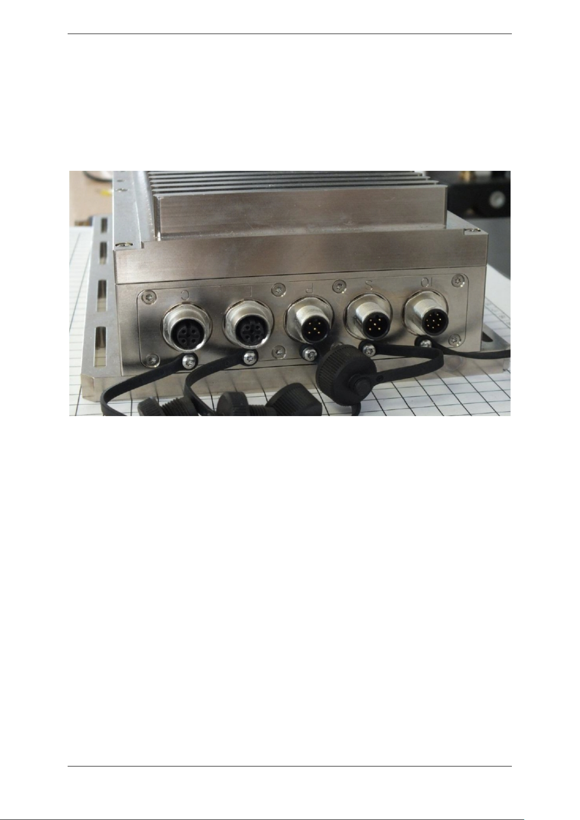
3.2.1 TEMPRIS PRO Connections and Interfaces
The sockets of the TEMPRIS PRO interrogation unit are labelled to limit the risk of
incorrectly connecting the TEMPRIS device. The following image shows the power supply
(label “P”) and Ethernet (label “E”) connections of the TEMPRIS PRO interrogation unit.
The “C”, “S” and “IO” connections are unused or for service purposes only.
Figure 3-3: TEMPRIS PRO Connections with Labels
TEMPRIS System Setup Page 25 of 80
Page 26
TEMPRIS User Manual
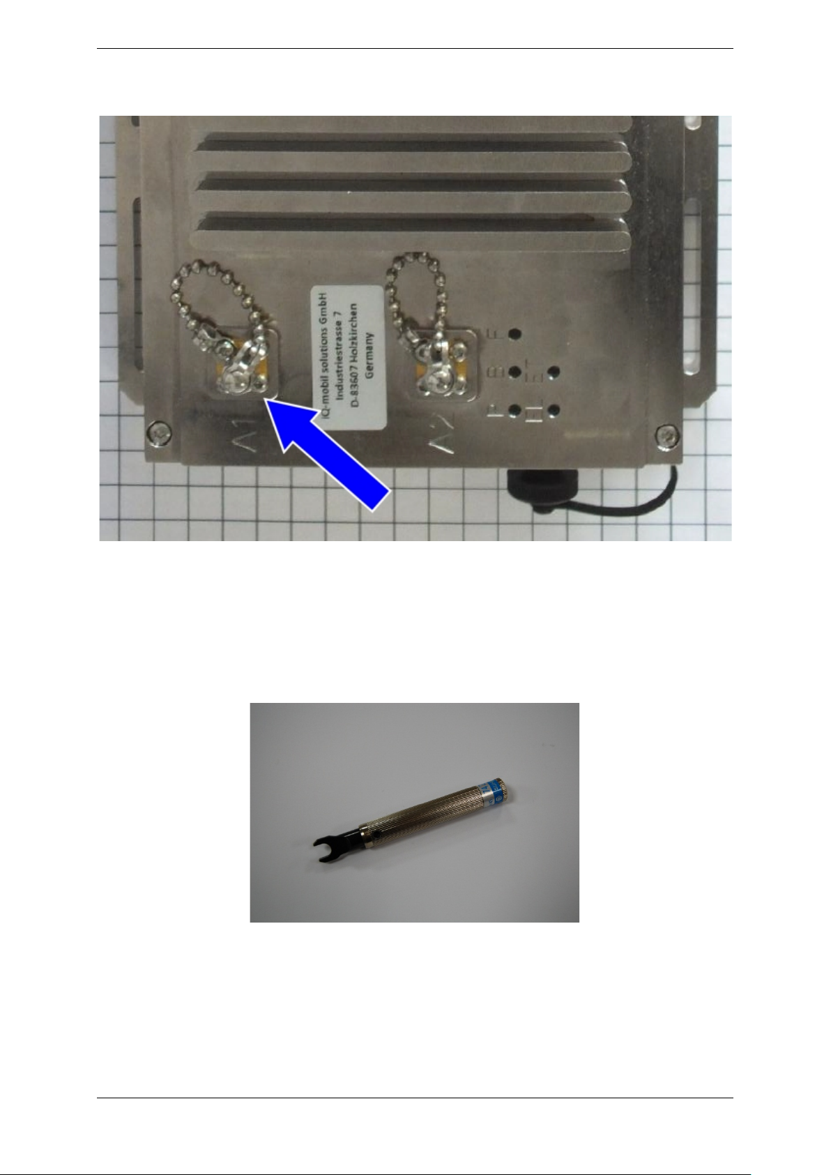
The following image shows the TEMPRIS PRO antenna connection (label “A1”).
Figure 3-4: TEMPRIS PRO Antenna Connection A1
Note
You have to screw the antenna cable connection fully into the antenna socket A1 on the
TEMPRIS interrogation unit. We recommend that you use a torque wrench to avoid any
damage to the antenna cable.
Figure 3-5: Torque Wrench
TEMPRIS System Setup Page 26 of 80
Page 27
TEMPRIS User Manual
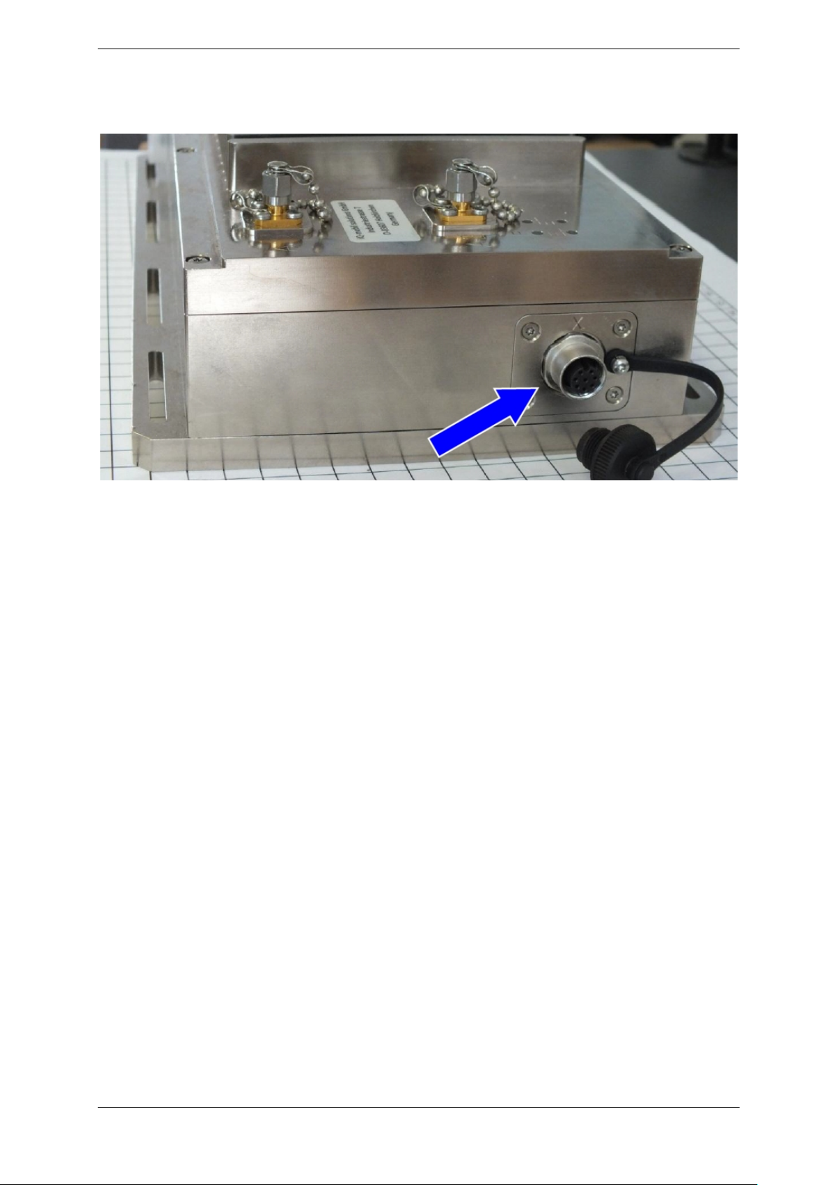
The following image shows the (optional) TEMPRIS PRO antenna multiplexer connection
(label “X”).
Figure 3-6: TEMPRIS PRO Antenna Multiplexer Connection X
TEMPRIS System Setup Page 27 of 80
Page 28
TEMPRIS User Manual
3.2.2 TEMPRIS LAB Connections and Interfaces
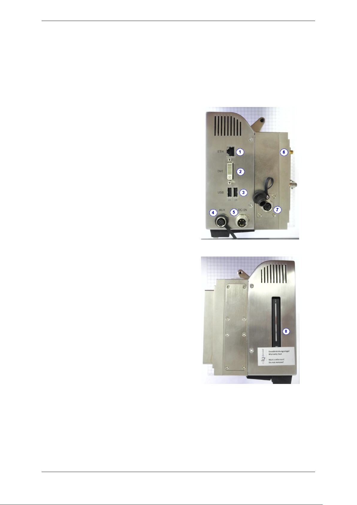
The following image shows the TEMPRIS LAB connections and interfaces. TEMPRIS LAB
provides two USB interfaces which can be used to connect peripheral USB devices such
as keyboard, mouse, USB memory drive, external hard drive, etc.
1 External Ethernet connection
2 VGA Interface
3 USB-connections
4 AUX connection (optional)
5 Power Supply
6 SMA Antenna connection
7 Antenna Multiplexer connection (optional)
8 Data Storage
(only for service purposes)
Figure 3-7: TEMPRIS LAB Connections and Interfaces
TEMPRIS System Setup Page 28 of 80
Page 29
TEMPRIS User Manual
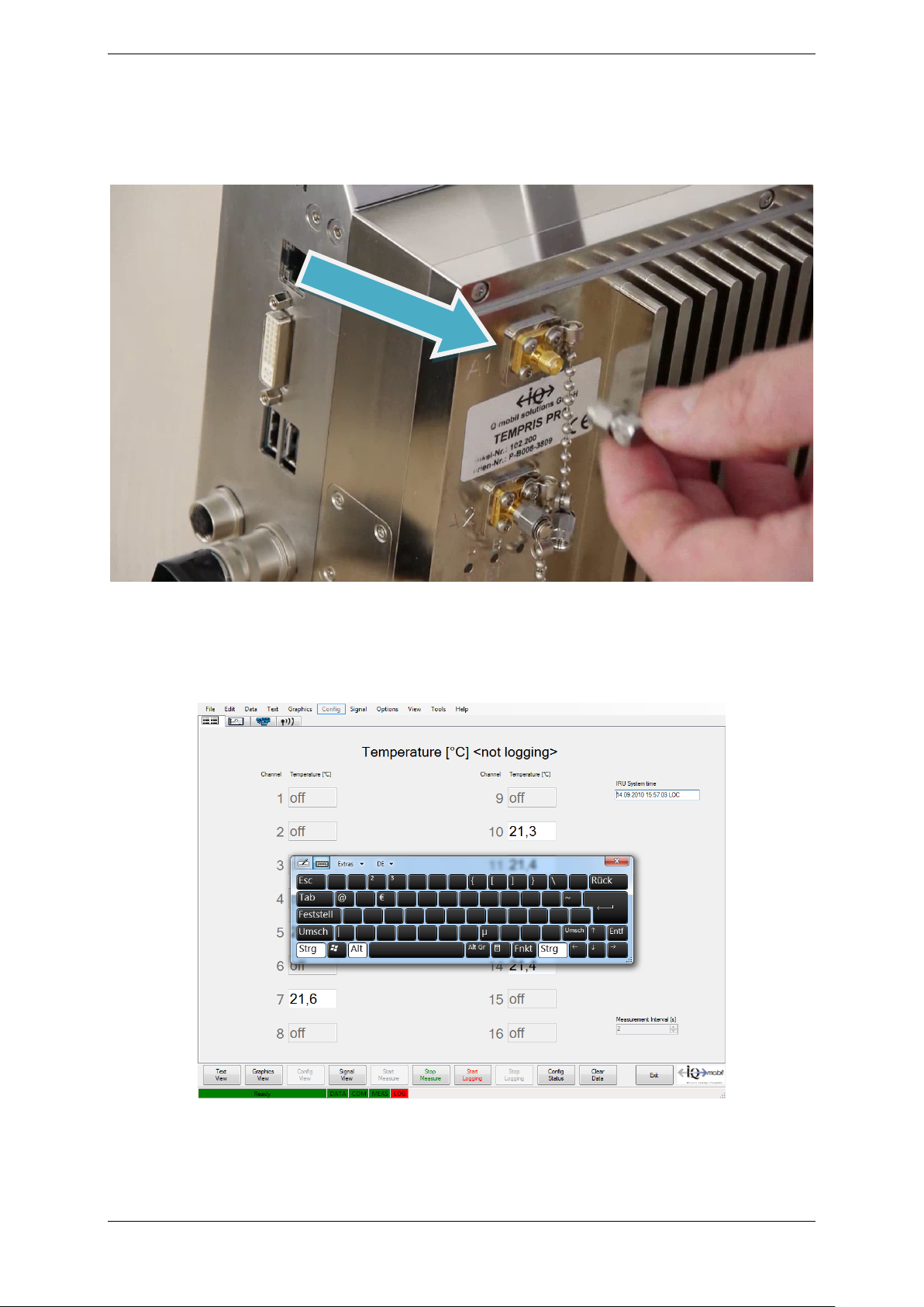
The following image shows the TEMPRIS LAB antenna connection (label “A1”). You have
to screw the antenna cable connection fully into the antenna socket A1 on the TEMPRIS
LAB interrogation unit. Take care not to damage the antenna cable in the process. We
recommend that you use a torque wrench (see Figure 6-5).
Figure 3-8: TEMPRIS LAB Antenna Connection A1
The TEMPRIS LAB system is equipped with touch screen functionality and a virtual
keyboard option.
Figure 3-9: TEMPRIS LAB Virtual Keyboard
TEMPRIS System Setup Page 29 of 80
Page 30

Page 31
TEMPRIS User Manual
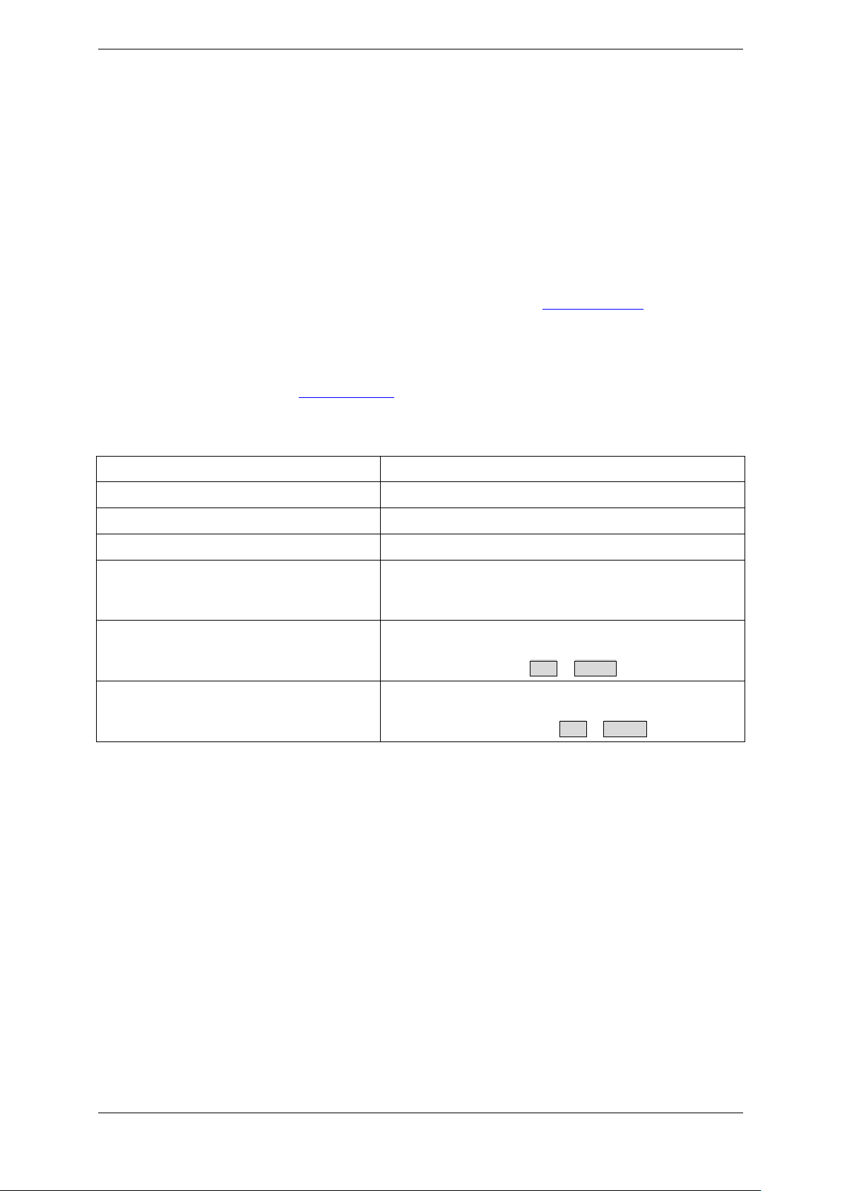
Operating system
Microsoft Windows 7 / Vista / XP
Processor
>= 1 GHz
Main Memory (RAM)
>= 1 Gigabyte
Hard disk space
>= 10 Gigabytes
Screen / graphic resolution
Colour screen
Graphic enhancement recommended
Adobe Reader
for accessing/reading the supplied TEMPRIS
PDF format through Help - Manual
Web Browser (e.g. Internet Explorer)
For accessing/reading the supplied
in HTML format through Help - Tutorial
3.3 TEMPRIS DataServer Installation
TEMPRIS LAB systems are delivered with a valid TEMPRIS DataServer software
installation. I.e., a TEMPRIS DataServer installation is usually only necessary for software
updates and/or on computers for TEMPRIS PRO systems.
3.3.1 TEMPRIS DataServer System Requirements
The TEMPRIS DataServer software runs on different hardware platforms.
TEMPRIS LAB (laboratory system) comes with an integrated Windows 7 PC, which meets
the system requirements listed in table 3-1. Please see chapter 3.2.2
TEMPRIS LAB connections.
TEMPRIS PRO (production system) can be operated with a PC/laptop provided by iQ-
mobil (recommended) or with your own PC/laptop with the system requirements listed in
the table below. Please see chapter 3.2.1
Table 3-1: TEMPRIS DataServer System Requirements
for the required cable connections.
for external
Resolution: 1280x1024 or higher
DataServer User Manuals which are available in
supplementary documentation which is available
TEMPRIS DataServer System Reuirements Page 31 of 80
Page 32

TEMPRIS User Manual
3.3.2 New Installation
The TEMPRIS DataServer software is delivered with a memory-stick. Please navigate to
the following directory on the memory stick:
\DataServer
Start the TEMPRIS DataServer setup program from the above directory:
setup.exe
Follow the instructions of the TEMPRIS DataServer setup program to complete the
software installation.
Unless otherwise specified during setup, the TEMPRIS DataServer software is installed in
the “Program Files” directory on drive C. The TEMPRIS DataServer setup program
creates a TEMPRIS DataServer program icon on your desktop and in the Windows Start
menu through All Programs – iQ-mobil - TEMPRIS DataServer.
3.3.3 Update Installation
If an old version of the TEMPRIS DataServer is already installed on your system, then
you must remove the old version before installing the new version.
Once the old TEMPRIS DataServer is removed, you can proceed with the installation of
the new version as described in chapter 5.1
.
TEMPRIS DataServer System Reuirements Page 32 of 80
Page 33

TEMPRIS User Manual
4 TEMPRIS DataServer User Interface and
Function Reference
This section describes the TEMPRIS DataServer software. I.e., the information in this
section refers to PC-based TEMPRIS systems, and does not necessarily apply to PLCbased TEMPRIS systems. In case of PLC-based systems, it is, however, possible to
operate the TEMPRIS DataServer software without any restrictions simultaneously with
the TEMPRIS interrogation unit as data logger and/or visualization tool through a PC,
laptop or Ethernet interface.
Please consider the following advice before starting TEMPRIS DataServer:
• Please deactivate any features, which could trigger automated Windows
restarts (such as, e.g., “Restart after automatic updates”), as this will interrupt
any active data logging and might result in the loss of valuable measuring data.
• In principle, there are no lock-ups of access to the TEMPRIS DataServer
operation. Access is, however, logged in a special activity log, so that the use
of the TEMPRIS DataServer is traceable. In case of sensitive data situations, it
is, therefore, recommended to set up different access accounts (with
PASSWORD) under Windows. These will then be logged, and will make the
respective user recognizable in chronological order.
In a TEMPRIS system, the following important definition is valid:
The term “channel” indicates the assignment (“mapping”) of a TEMPRIS sensor to a
TEMPRIS data stream (data record). Sensor to channel assignments allow for
measurement data from different sensors to be distinguished. TEMPRIS supports up to
16 sensor assignments, thus supporting simultaneous monitoring of up to 16
temperature measurement data channels. Sensors with different frequencies are
assigned to different channels unless a special setup (e.g., with antenna multiplexing) is
being used. The sensor assignments are stored in TEMPRIS configuration files. The
“Config View” (see chapter 6.5.) provides functions for saving and loading TEMPRIS
configuration files for different sensor sets, antenna configurations, etc.
TEMPRIS DataServer User Interface and Function Reference Page 33 of 80
Page 34

TEMPRIS User Manual
4.1 TEMPRIS DataServer Features
With TEMPRIS DataServer, you can
• configure your TEMPRIS system according to your requirements:
• Select the number of active sensors (1 to 16) – Load/set sensor calibration
coefficients (polynomial)
• Select the desired interface(s)
• Select the desired data rate
• Select the sensor measurement range
• Optionally assign sensors to different antennas (“multiplexing”)
• save TEMPRIS measuring data permanently (“logging”):
• Select log directory and log file name
• Activate and deactivate data logging
• visualize TEMPRIS measuring data online or offline:
• Temperature sequences in graphic form (“Plots”)
• Temperature representation in numeric form (“Listings”)
• Representation of the measuring data quality (S/N, signal to noise-ratio)
• Selection and windowing of measuring data (zoom functions)
• Representation of temperature distributions (3D)
• distribute and retrieve TEMPRIS measuring data over a network via:
• Ethernet
• Modbus 4 to 20 mA Current Loop interface
• print TEMPRIS measuring data (“hardcopy” function)
• organize data access and system configurations:
• Password protection, “traceability”
• Protection of log files against manipulation (“21 CFR Part 11”)
TEMPRIS DataServer User Interface and Function Reference Page 34 of 80
Page 35
TEMPRIS User Manual
4.2 Program Start
The TEMPRIS DataServer can be started by double-clicking the TEMPRIS DataServer
program icon on the desktop or in the Windows Start menu.
Please note that the TEMPRIS DataServer start-up procedure can last up to some 20
seconds.
4.1.1 TEMPRIS LAB Start-up Screen
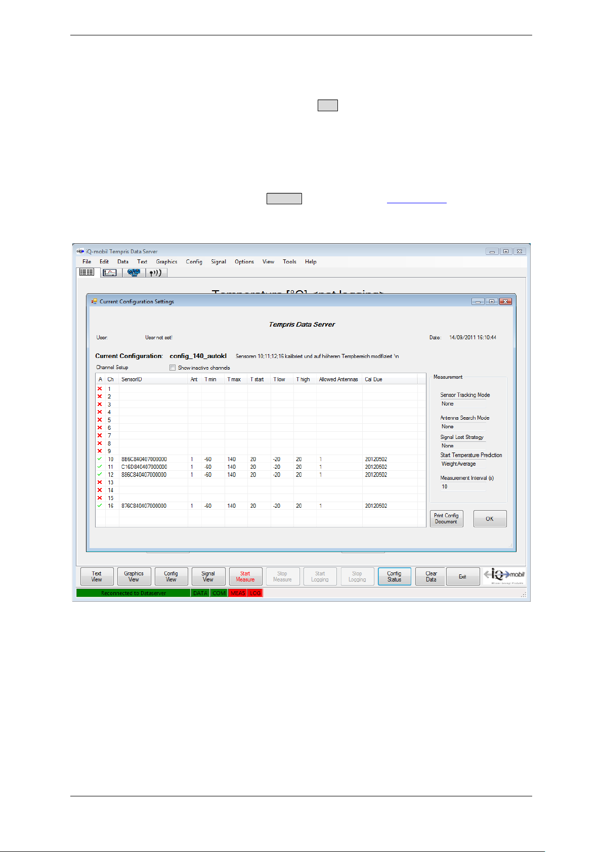
TEMPRIS LAB automatically runs the Connect command (see chapter 7.4) upon start-up,
thus triggering the display of the “Current Configurations Setup” dialog as shown in the
following screenshot.
Figure 4-1: TEMPRIS LAB Start-up Screen
TEMPRIS DataServer User Interface and Function Reference Page 35 of 80
Page 36
TEMPRIS User Manual
4.1.2 TEMPRIS PRO Start-up Screen
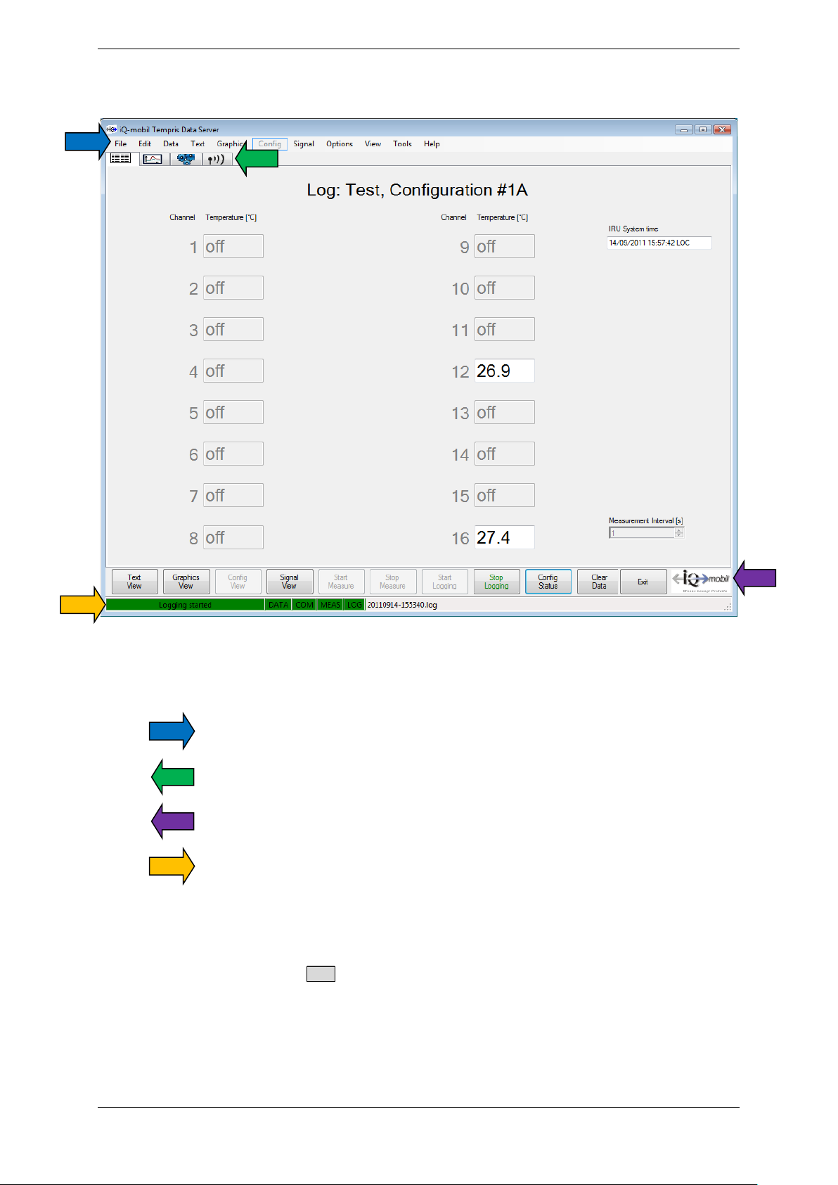
Figure 4-2: TEMPRIS PRO Start-up Screen
The TEMPRIS DataServer user interface includes of the following special areas:
Menu Bar
Function Tab
Toolbar with Command Buttons
Status Bar
The respective menu items and command buttons are described in the following
chapters.
The function tab contains View commands for selecting different views. For easier
touchscreen operation, these commands are also provides through large command
buttons in the toolbar at the bottom.
TEMPRIS DataServer User Interface and Function Reference Page 36 of 80
Page 37
TEMPRIS User Manual
Status Bar Element
Display
Connection Status
Ready
Error message
Receive Status
DATA = data link connected
DATA = data link disconnected
Command Status
COM = command link connected
COM = command link disconnected
Measurement Status
MEAS = measuring started
MEAS = measuring status undefined
Logging Status
LOG = logging on log file switched on
LOG = logging on log file switched off
Connection Status
Receive Status
Command Status
Measurement Status
Logging Status
Name of current log file
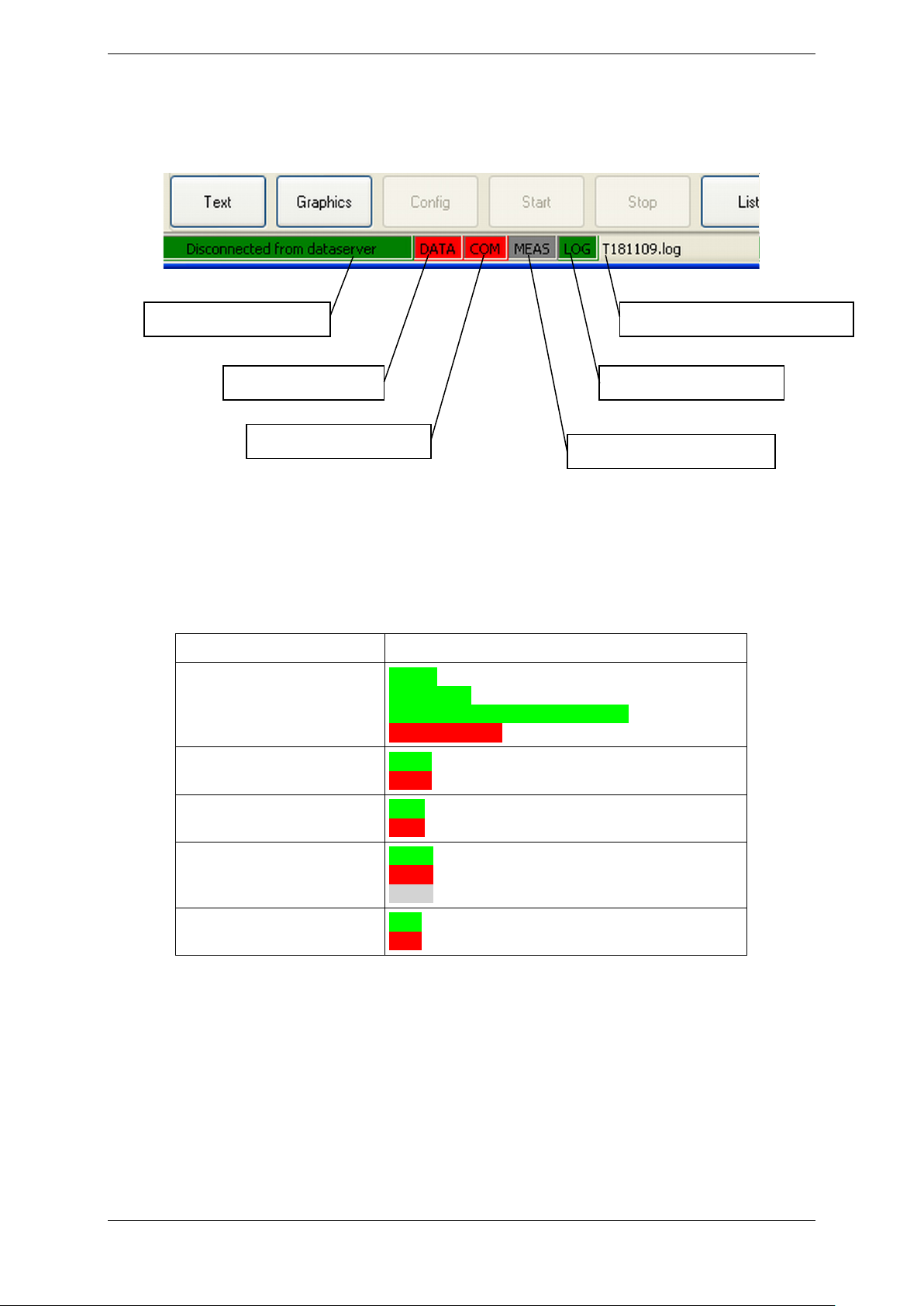
4.3 Status Bar
The following figure shows the TEMPRIS DataServer status bar elements.
Figure 4-3: TDS Status Bar Elements
Table 4-1 provides an overview of TEMPRIS DataServer status bar elements and
messages.
Table 4-1: TEMPRIS DataServer Status Bar Elements
Connected
Disconnected from DataServer
MEAS = measuring stopped
TEMPRIS DataServer User Interface and Function Reference Page 37 of 80
Page 38
TEMPRIS User Manual
4.4 Interface Configuration
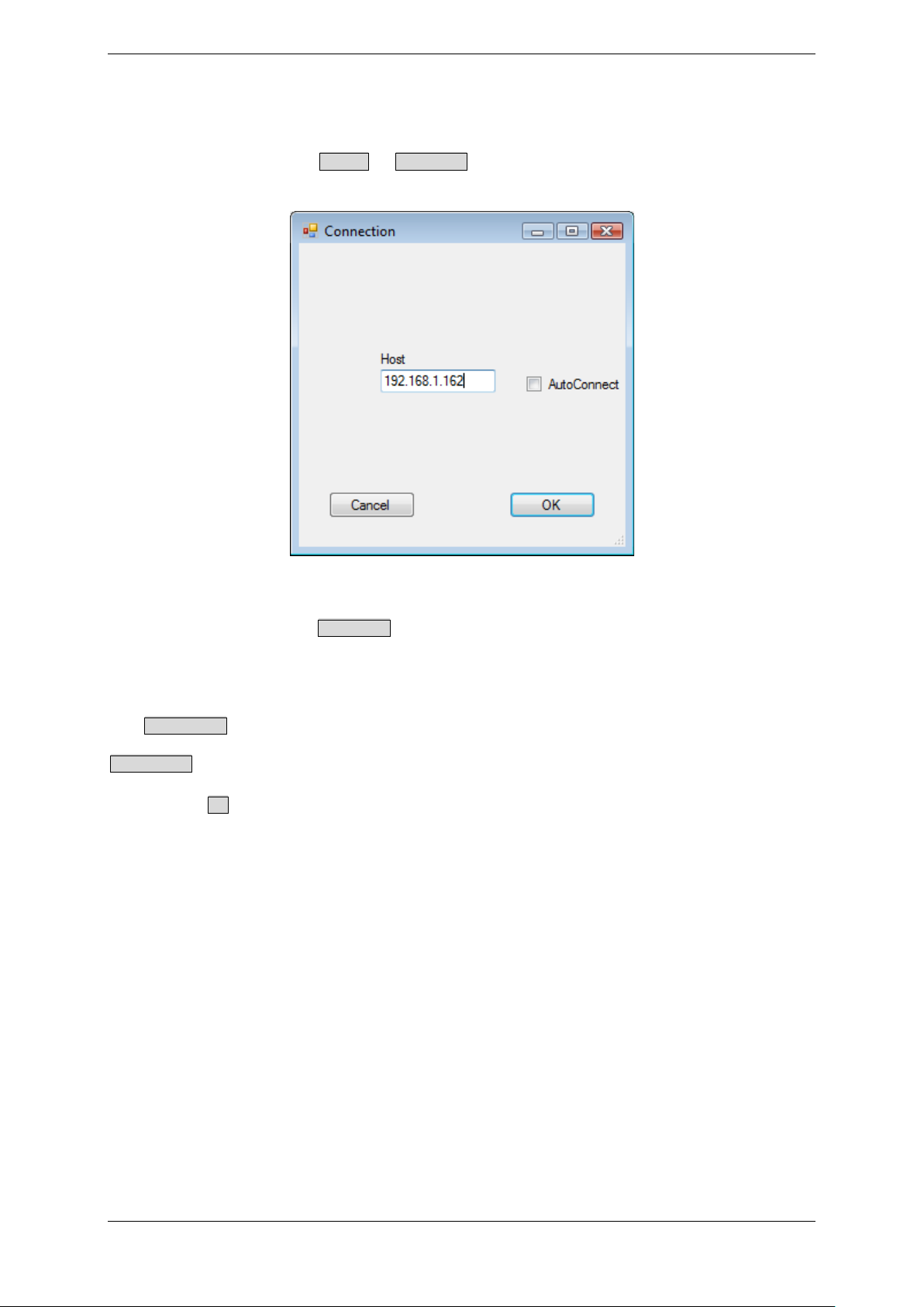
The TEMPRIS DataServer communicates with the TEMPRIS interrogation unit through an
Ethernet connection. The Options – Connection function activates a dialog for configuring
the Ethernet connection.
Figure 4-4: TDS Options - Connection
The “Host” field in the Connection dialog displays the IP address of your TEMPRIS
interrogation unit. In most cases the factory setting for the IP address should work.
However, the IP address can be changed should this be necessary to resolve an address
conflict with another device on your network.
The AutoConnect option causes the TEMPRIS DataServer software to connect automatically
to the specified IP address upon program start-up. We recommend to activate the
AutoConnect option on TEMPRIS LAB systems.
Clicking the OK button activates the current dialog settings and stores them permanently
on your computer.
Notes
• Make sure that the provided Ethernet cable is plugged in between the TEMPRIS
interrogation unit and your computer or laptop.
• In accordance with your data, the IP address has been preset by factory in
correspondence with the IP address of your computer / laptop. You can find the
preset IP address on a label of the TEMPRIS controller casing. This IP address is
temporary, the user has the possibility of changing this address later (see
documentation IRU-2 maintenance), e.g. in case of computer replacement, etc.
It is recommended to note the changed IP address and to change the label on
the casing accordingly.
• Your interface selection and configuration is stored on your computer and is
automatically loaded when the TEMPRIS DataServer is started the next time.
TEMPRIS DataServer User Interface and Function Reference Page 38 of 80
Page 39
TEMPRIS User Manual
4.5 Establishing the Data Connection between PC and TEMPRIS Interrogation Unit
Note
The TEMPRIS DataServer of the TEMPRIS LAB version automatically connects to the
TEMPRIS interrogation unit upon start-up.
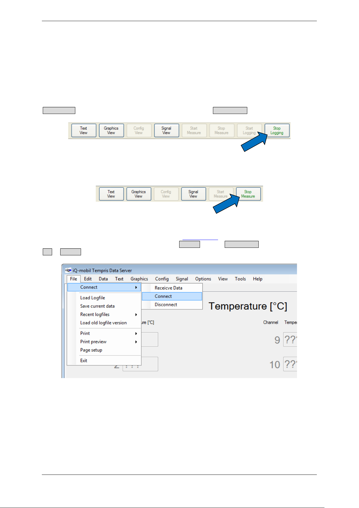
In case of current measurement / logging operation, you have to stop both logging with
Stop Logging (see Figure 7-5) and the measurement with Stop Measure (see Figure 7-6).
Figure 4-5: TDS Toolbar - Stop Logging
Figure 4-6: TDS Toolbar – Stop Measure
After configuring the Ethernet interface (see chapter 4.4
to the TEMPRIS interrogation unit with the Connect or the Receive Data function from the
File – Connect submenu.
), the PC or laptop can connect
Figure 4-7: TDS File – Connect Submenu
TEMPRIS DataServer User Interface and Function Reference Page 39 of 80
Page 40
TEMPRIS User Manual
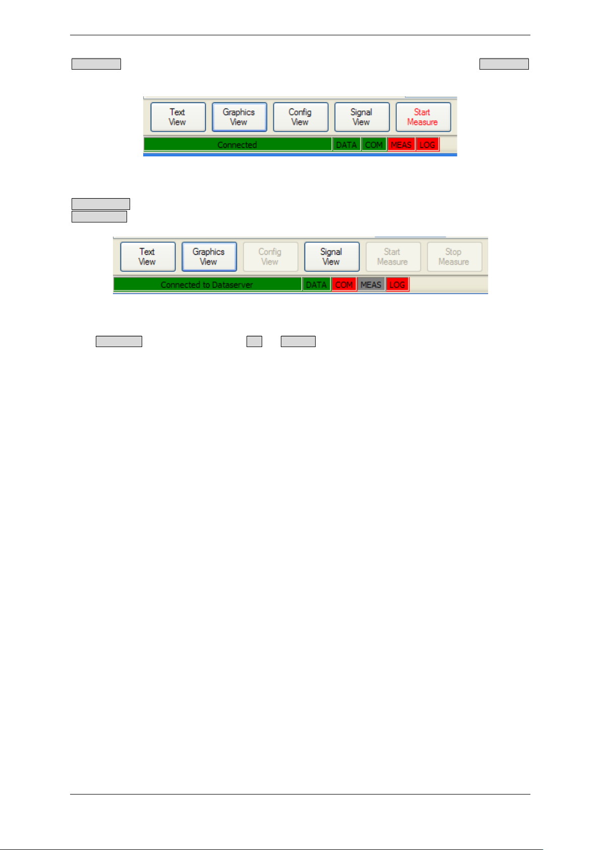
Connect All enables both data and command communications (bi-directional). Connect All
mode is indicated in the status bar as follows:
Figure 4-8: TDS Status Bar – Connect Indicators
Receive Data enables data communications only (only DATA receipt, no COMmands).
Receive Data mode is indicated in the status bar as follows:
Figure 4-9: TDS Status Bar – Receive Data Indicators
The Disconnect function from the File – Connect submenu stops any active logging and
measurement on the PC and closes the existing interrogation unit.
TEMPRIS DataServer User Interface and Function Reference Page 40 of 80
Page 41
TEMPRIS User Manual
General
Channel / Antenna
Measurement
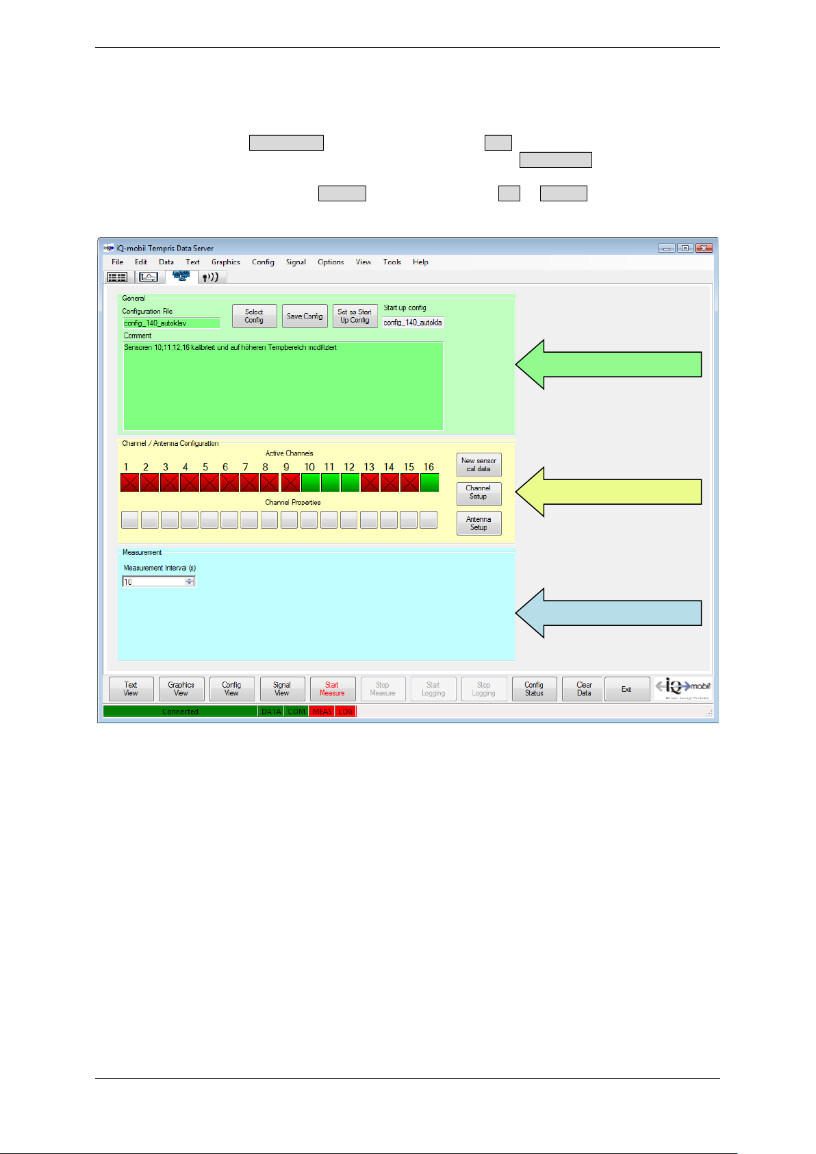
4.6 Config View
The „Config View“ for displaying and configuring the TEMPRIS system settings can be
activated with the Config View function from the View menu or by clicking the
corresponding function index tab. Please note that the Config View function is only
available if a connection between the TDS software and the TEMPRIS interrogation unit is
has been established (with the Connect function from the File – Connect menu and neither
logging nor measuring is active.
Figure 4-10: TDS Config View
The TDS “Config View” consists of several blocks which are described in the following
sections.
TEMPRIS DataServer User Interface and Function Reference Page 41 of 80
Page 42
TEMPRIS User Manual
1 2 3
4
4.6.1 Config View - General
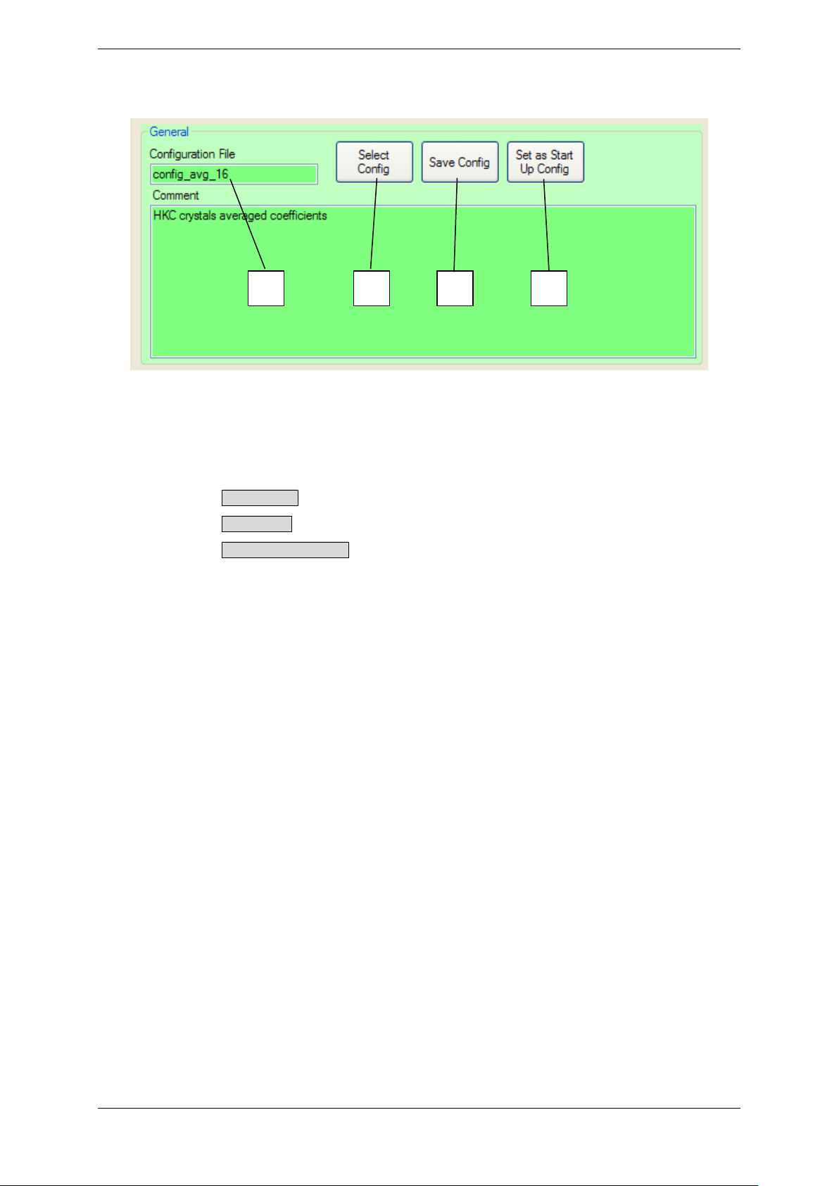
Figure 4-11: TDS Config View - General
The “General” block of the “Config View” provides the following controls and functions:
• The currently loaded configuration file (1)
• Button Select Config for selecting/loading a saved configuration (2)
• Button Save Config for saving the current configuration (3)
• Button Set as Start Up Config for selecting an existing configuration file as default
configuration to be loaded upon start-up (4)
TEMPRIS DataServer User Interface and Function Reference Page 42 of 80
Page 43
TEMPRIS User Manual
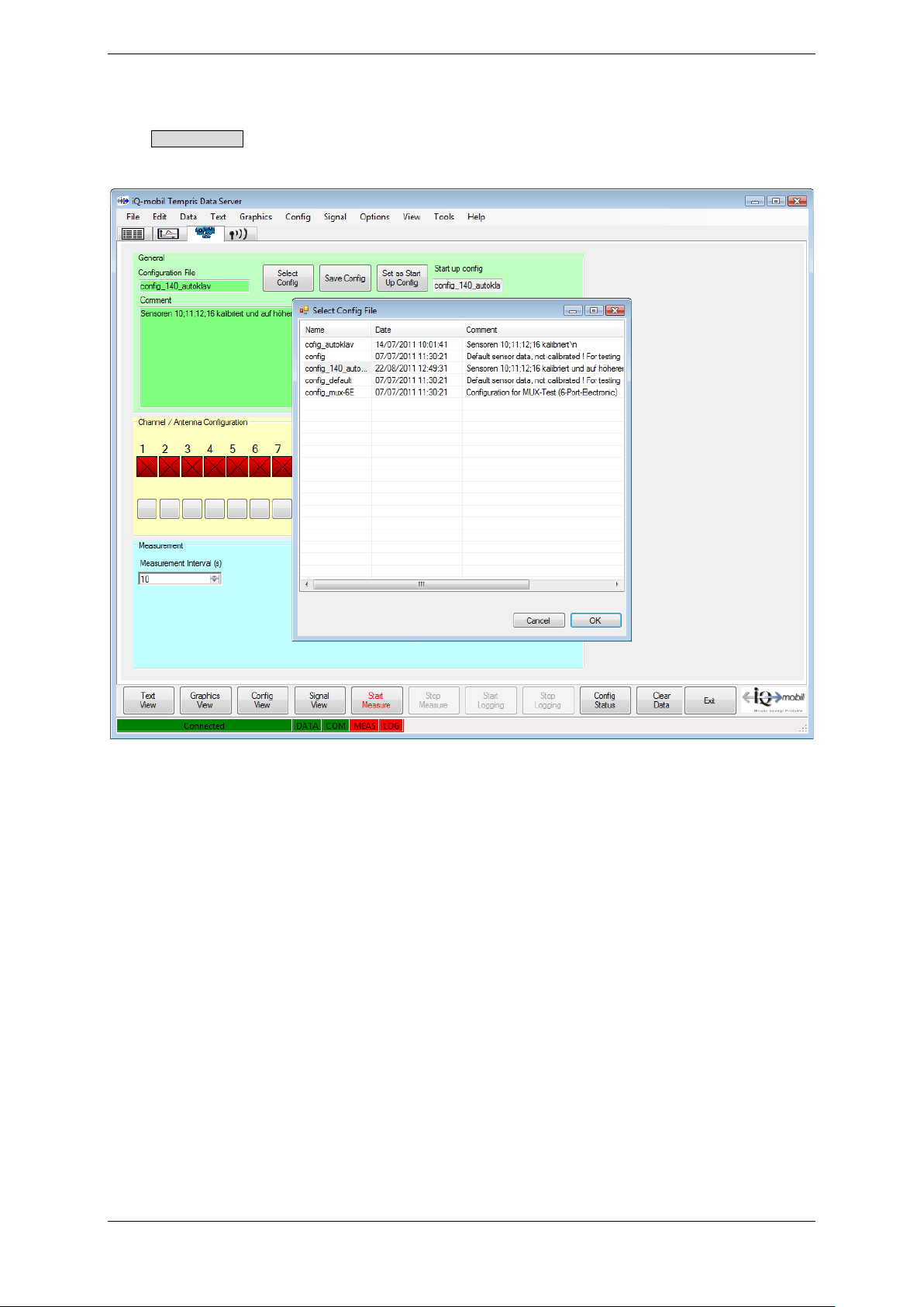
“Select Config” (2):
The Select Config function activates a dialog for selecting and loading an existing
configuration file:
Figure 4-12: TDS Config View – General – Select Config
TEMPRIS DataServer User Interface and Function Reference Page 43 of 80
Page 44
TEMPRIS User Manual
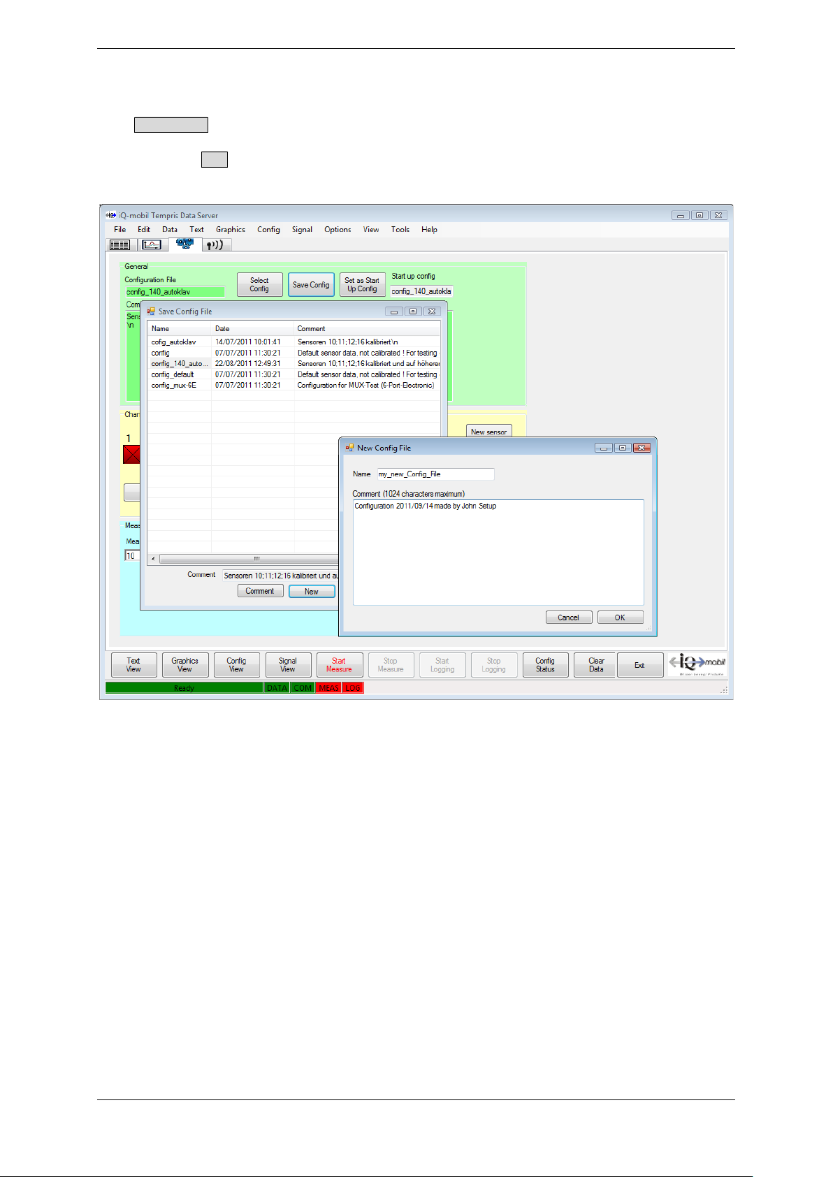
Save Config (3):
The Save Config function activates a dialog for saving the current configuration to a
configuration file. Selecting an existing configuration file overwrites the configuration in
that file. The New option allows for the creation of a new configuration file with userdefined name and optional comments.
Figure 4-13: TDS Config View – General – Save Config
TEMPRIS DataServer User Interface and Function Reference Page 44 of 80
Page 45
TEMPRIS User Manual
1 2 4 3 5
4.6.2 Config View - Channel / Antenna Configuration
Figure 4-14: TDS Config View – Channel / Antenna Configuration
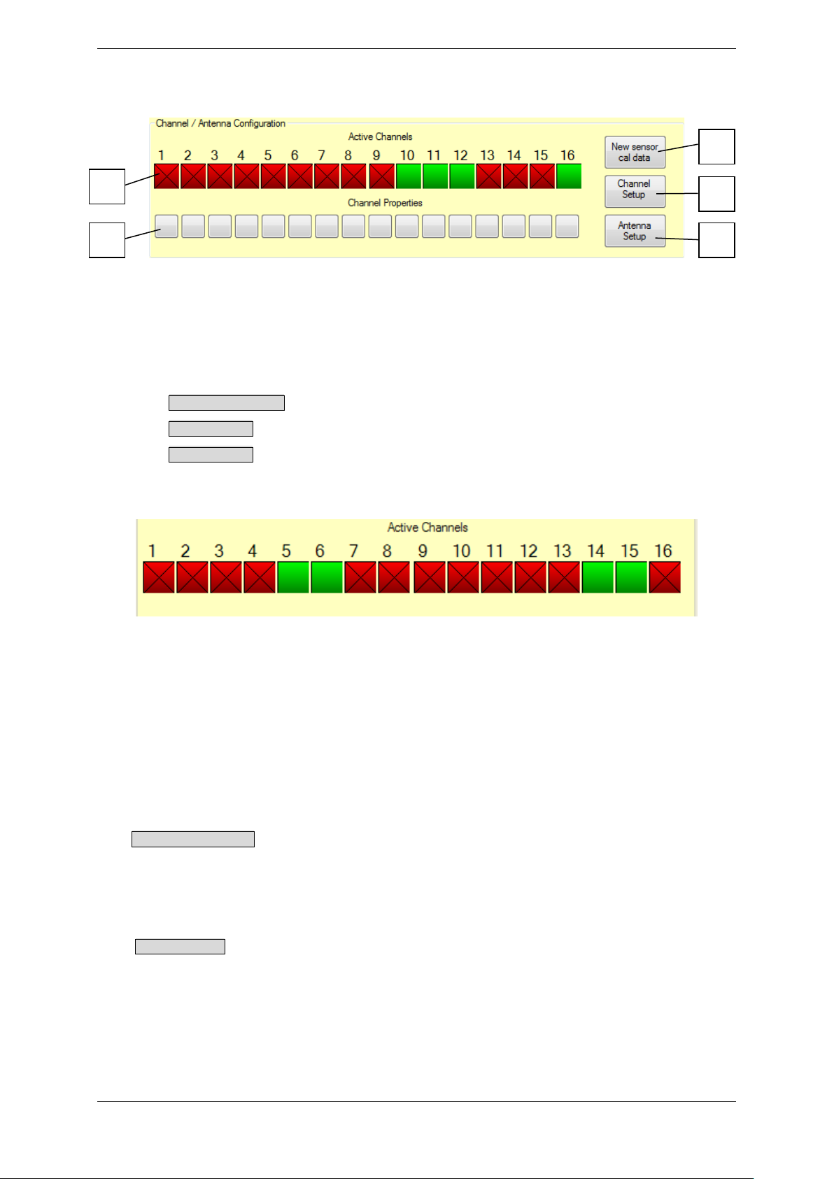
The “Channel / Antenna Configuration” block of the “Config View” provides the following
controls and functions:
• Activation / Deactivation of measurement channels (1)
• New sensor cal data loads sensor calibration data (2)
• Antenna Setup assigns antennas to channels (3)
• Channel Setup displays the channel assignments (4)
(1) Active Channels
Figure 4-15: TDS Config View – Channel / Antenna Configuration – Active
Channels
Green channel buttons are used to indicate activated channels. I.e., only the green
marked channels, respectively the sensors assigned to these channels, are activated for
measurement. Clicking a channel button toggles between channel “activated” (green)
and channel “deactivated” (red) mode. In the example above, the channels 5, 6, 14 and
15 are selected for measurement.
(2) New sensor cal data
The New Sensor cal data function allows (after recalibration or the use of new / additional
sensors) the loading of the corresponding calibration data from the PC / laptop on the
interrogation unit and their storage.
(3) Antenna Setup
The Antenna Setup function allows the corresponding assignment in case of antenna
multiplexing.
TEMPRIS DataServer User Interface and Function Reference Page 45 of 80
Page 46
TEMPRIS User Manual
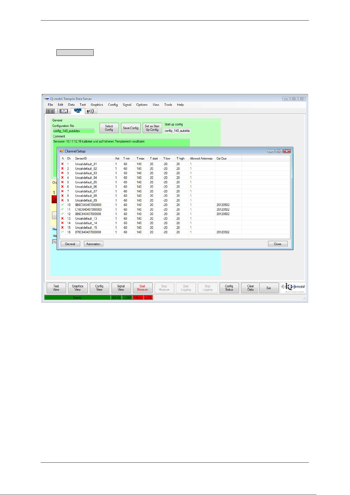
(4) Channel Setup
The Channel Setup function allows querying the current activation status of individual
channels (sensors) and corresponding measuring ranges.
The following screenshot shows a channel setup query with channels 5, 6, 14 and 15
activated.
Figure 4-16: TDS Config View – Channel / Antenna Configuration – Channel
Setup
The TEMPRIS data collection process supports different search strategies for finding the
sensors in the antenna field of the TEMPRIS interrogation unit. The TEMPRIS sensor
search procedure is similar to an automated channel scan on a car radio tuner. In order
to search as efficiently as possible, a search area has to be selected (similar to the FM,
VHF, etc. band selection on the car radio tuner).
The TEMPRIS search area is defined through the following temperature parameters:
• Tmin Temperature measuring range lower limit [°C]
• Tmax Temperature measuring range upper limit [°C]
• Tstart Temperature search start value [°C]
• Tlow Temperature search range lower limit [°C]
• Thigh Temperature search range upper limit [°C]
TEMPRIS DataServer User Interface and Function Reference Page 46 of 80
Page 47
TEMPRIS User Manual
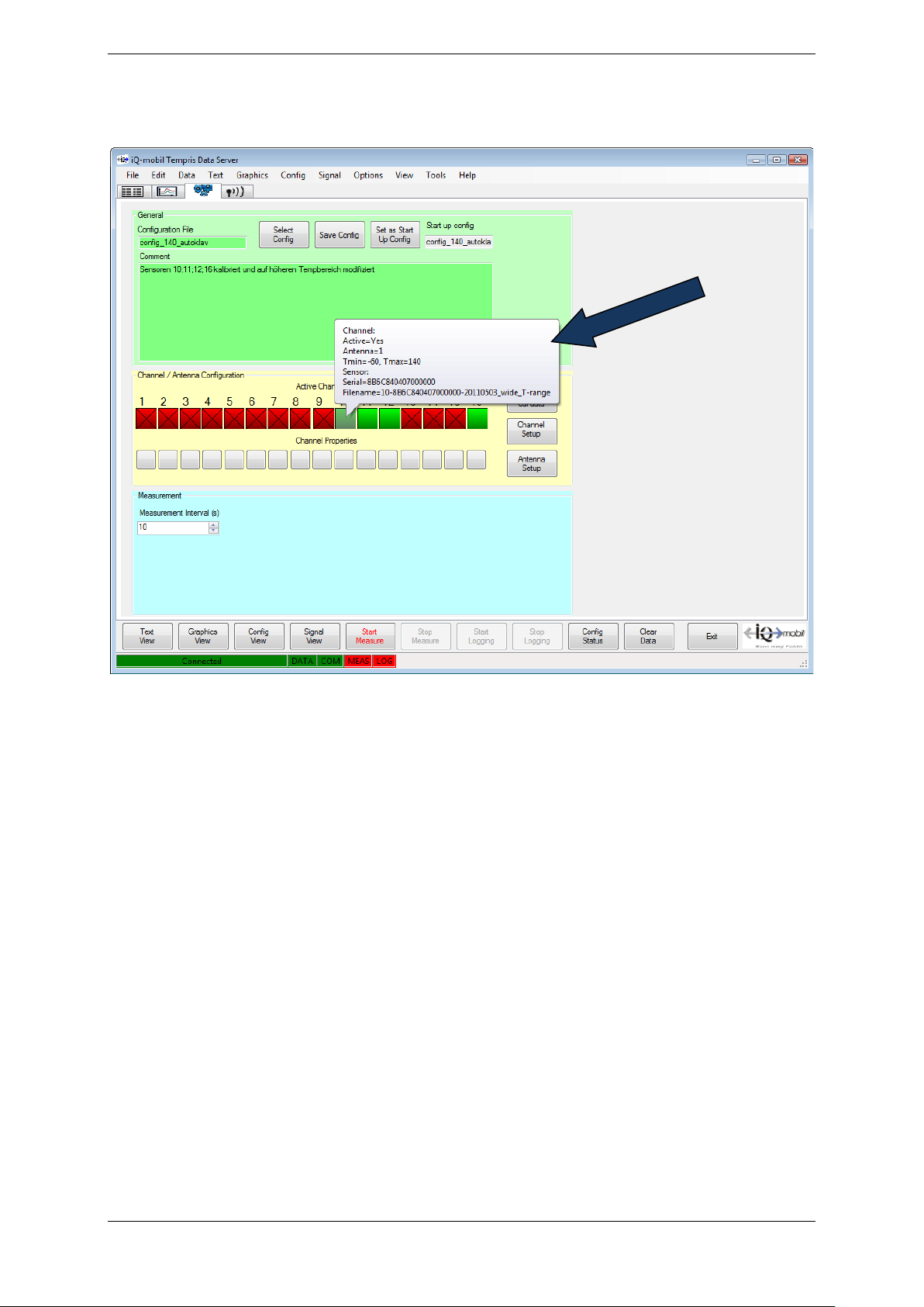
The assignment status of a channel is displayed in a tool tip when the mouse pointer is
moved over the channel indicator as illustrated in the following screenshot.
Figure 4-17: TDS Config View – Channel / Antenna Configuration – Channel
Tooltips
TEMPRIS DataServer User Interface and Function Reference Page 47 of 80
Page 48
TEMPRIS User Manual
1
2
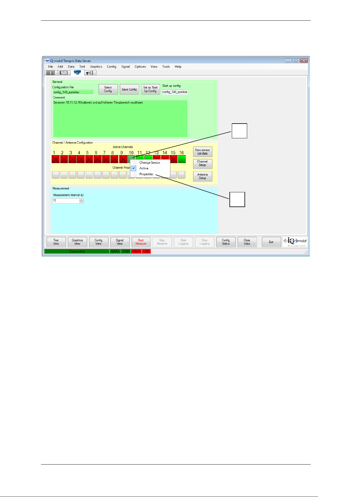
The measuring range and search parameters can be adjusted for each channel by clicking
the channel indicator with the right mouse button:
Figure 4-18: TDS Config View – Channel / Antenna Configuration – Channel
Settings
TEMPRIS DataServer User Interface and Function Reference Page 48 of 80
Page 49
TEMPRIS User Manual
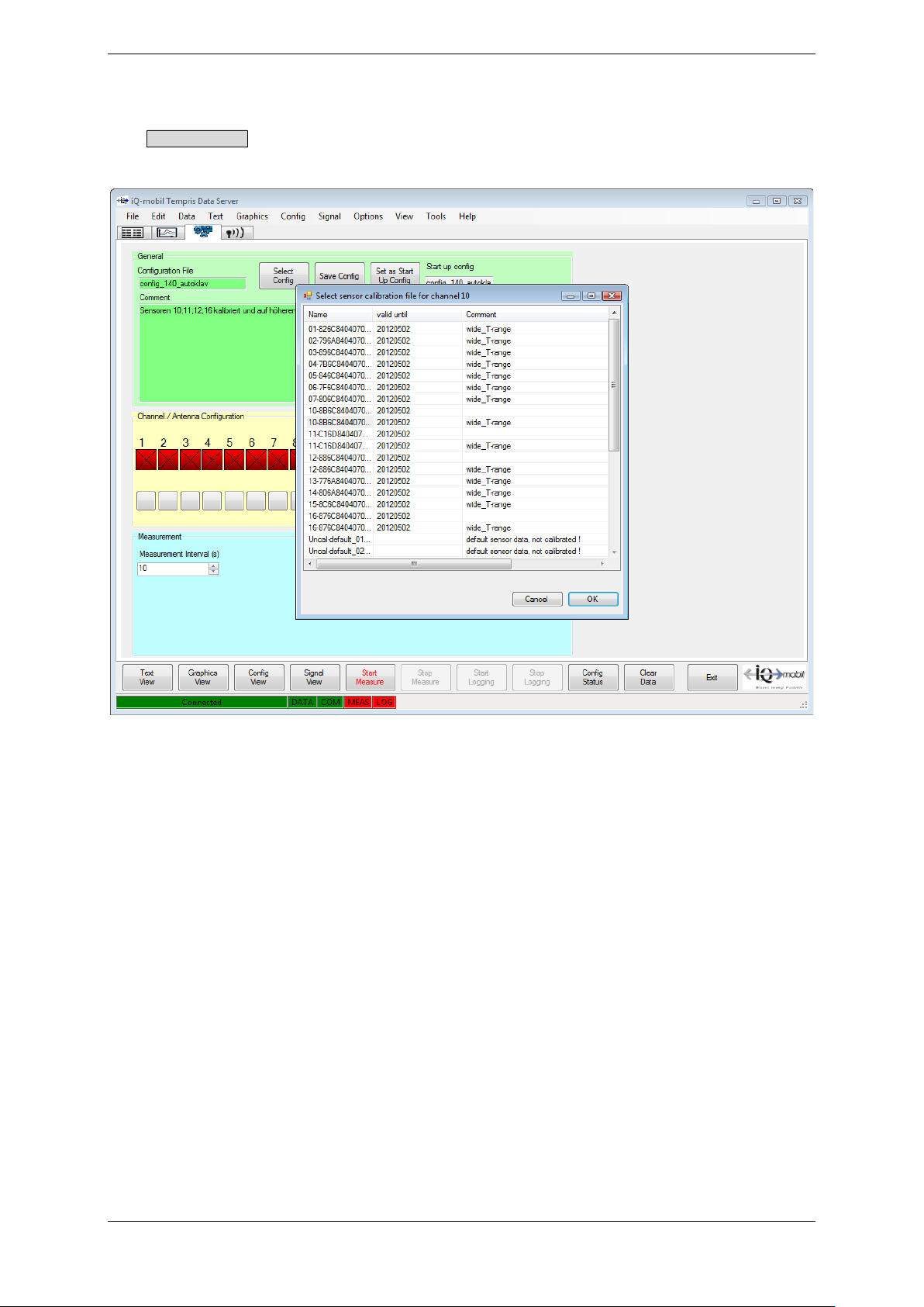
(1) Active Channels - Change Sensor:
The Change Sensor button activates a dialog for loading a sensor calibration file for the
selected channel/sensor.
Figure 4-19: TDS Config View – Channel / Antenna Configuration – Change
Sensor
TEMPRIS DataServer User Interface and Function Reference Page 49 of 80
Page 50
TEMPRIS User Manual
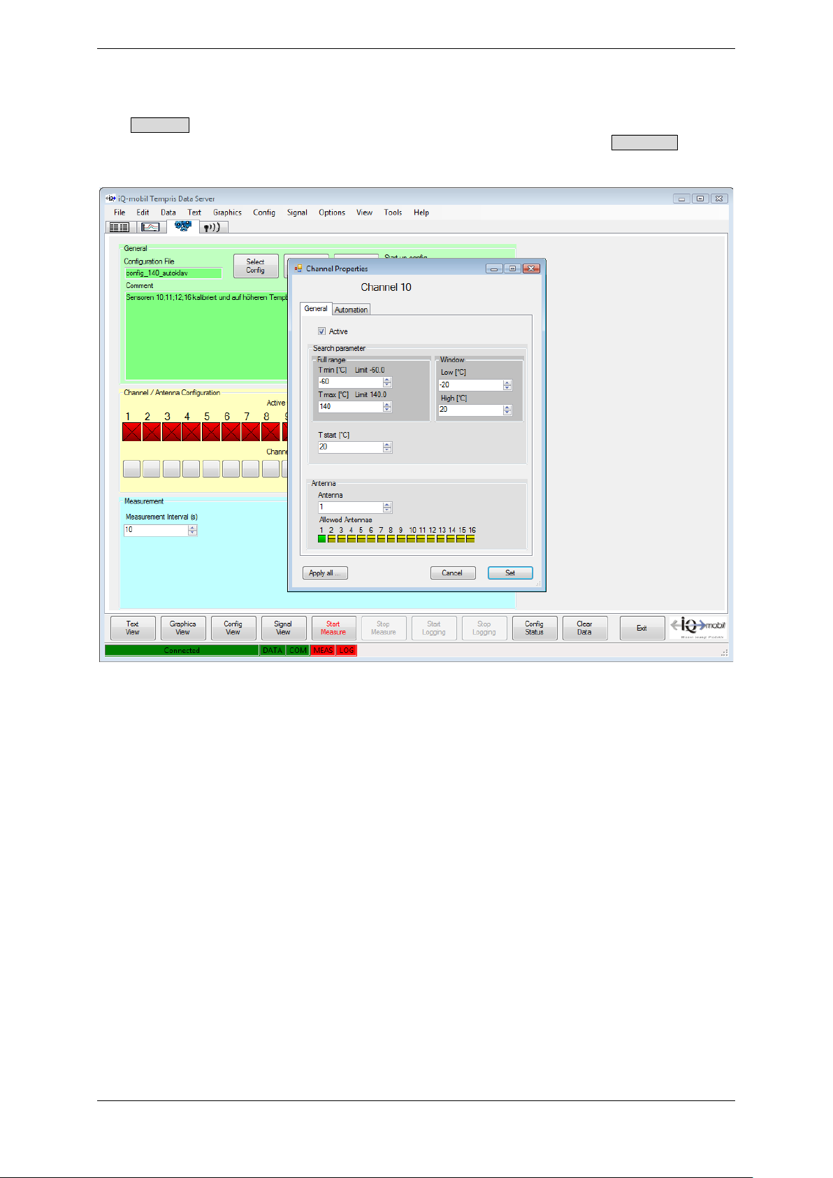
(2) Active Channels – Channel Properties:
The Properties button activates a dialog for displaying and specifying the measuring range
limits and search parameters for the selected channel/sensor. The Apply all… button
assigns the currently entered parameters to all channels/sensors.
Figure 4-20: TDS Config View – Channel / Antenna Configuration – Channel
Properties
TEMPRIS DataServer User Interface and Function Reference Page 50 of 80
Page 51

TEMPRIS User Manual
4.6.3 Config View - Measurement
Figure 4-21: TDS Config View - Measurement
The “Measurement Interval(s)” control sets the time resolution (time interval of
measurement points) for the active channels.
TEMPRIS DataServer User Interface and Function Reference Page 51 of 80
Page 52
TEMPRIS User Manual
4.7 Text View
As soon as the controller is connected, data from the activated channels is delivered if
these are in reachable distance in the antenna field of the controller. During active
measurement, the TEMPRIS interrogation unit continuously carries out a so-called sensor
search over the frequency ranges of the activated sensors. The duration of the search
period depends on various parameters (number of activated sensors, size of the search
window/range, signal quality, etc.).
You can switch between different views for displaying incoming data.
The „Text View“ for displaying the monitored temperature values can be activated with
the Text View function from the View menu or by clicking the corresponding function index
tab.
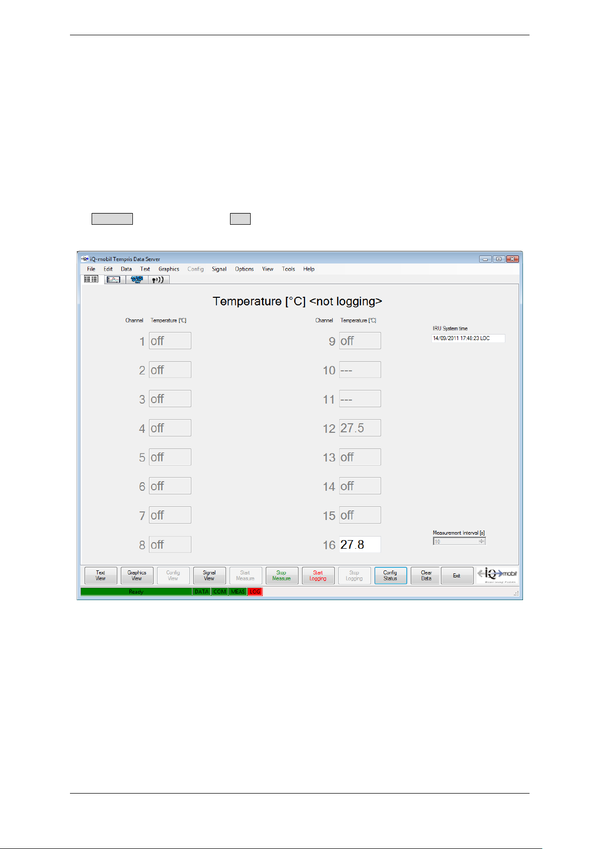
Figure 4-22: TDS Text View
TEMPRIS DataServer User Interface and Function Reference Page 52 of 80
Page 53

TEMPRIS User Manual
“Text View” displays the incoming values of the active measuring channels in the
selected temperature units (Celsius, Fahrenheit, Kelvin). Please note that the
temperature values are displayed with one decimal digit, yet the internal precision for
storing the temperature values in the TEMPRIS log files is much higher (<0.01° Kelvin).
The text view displays the temperature values in two columns. Channels 01 through 08
are displayed in the left column, and channels 09 through 16 are displayed in the right
column.
Inactive channels are greyed and marked with “off”.
If a channel (sensor) temporarily disappears out of the antenna field (in the example
above, the channel 14 has been briefly removed from the field), the last measured
temperature value (in the example 22.6°C) is represented in grey writing. As soon as a
“grey” channel (sensor) re-enters the antenna field, the currently measured temperature
value reappears in normal (black) writing.
In the right upper field of the screen, the time of the last measurement is updated.
The following temperature display units can be selected thorough Options – Preferences
(see below):
• Celsius
• Fahrenheit
• Kelvin
TEMPRIS DataServer User Interface and Function Reference Page 53 of 80
Page 54
TEMPRIS User Manual
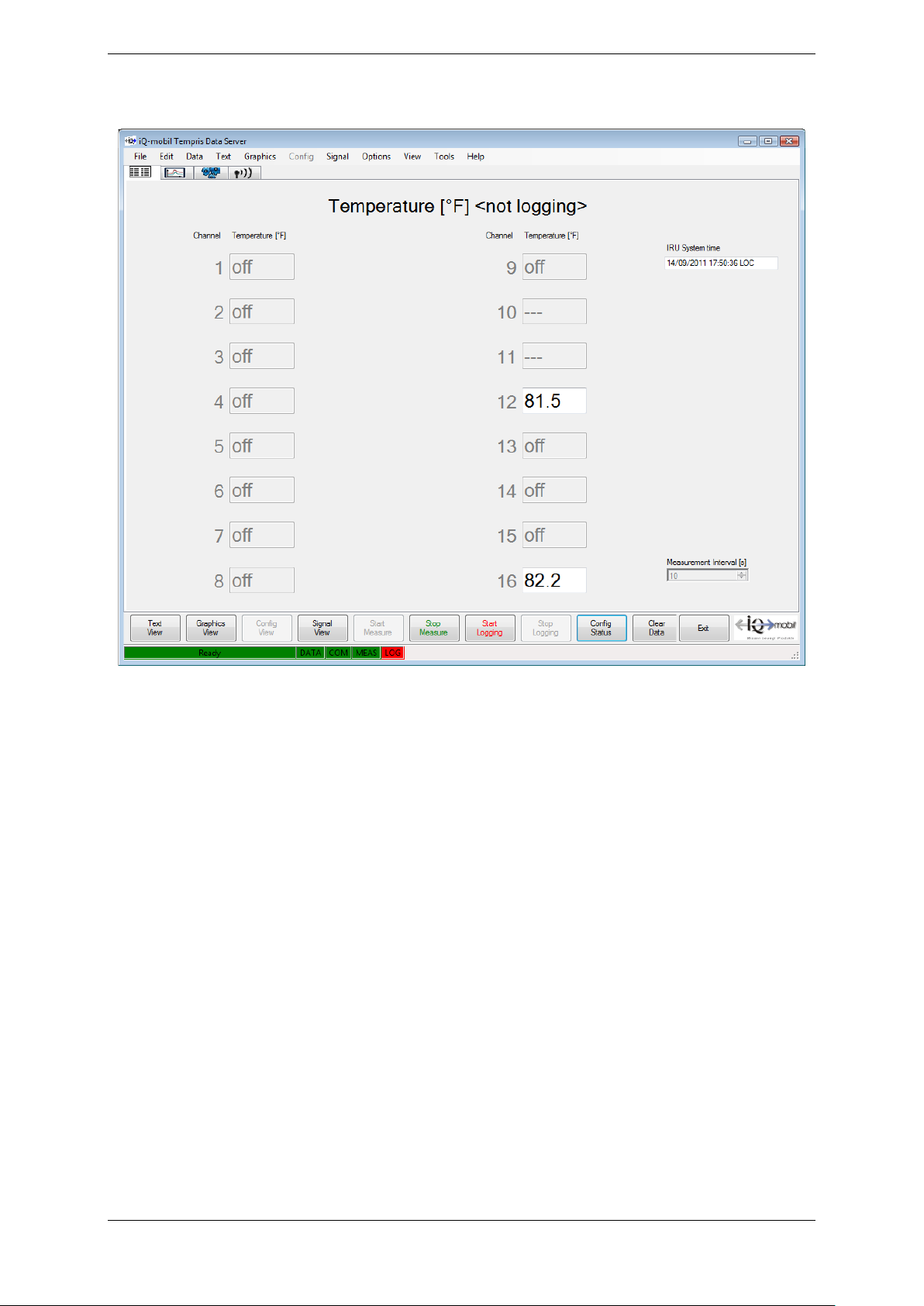
The following screenshot shows a text view display with Fahrenheit temperature units.
Figure 4-23: TDS Text View – Fahrenheit Temperature Display
TEMPRIS DataServer User Interface and Function Reference Page 54 of 80
Page 55
TEMPRIS User Manual
4.8 Graphics View
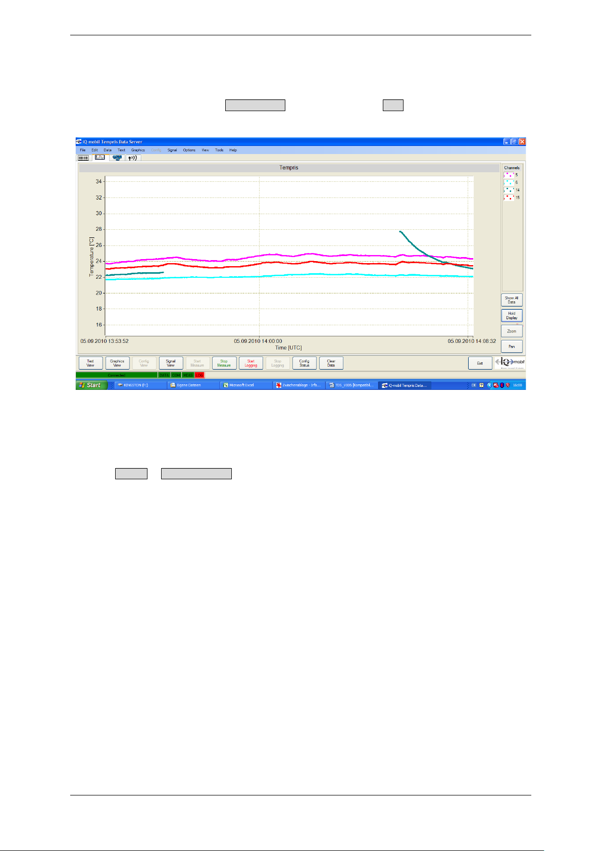
The „Graphics View“ displays a plot data view of the monitored data. The graphics view
can be activated through the Graphics View function from the View menu or by clicking the
corresponding function index tab.
Figure 4-24: TDS Graphics View
The ordinate (y-axis) of the graph represents the temperature in the chosen temperature
unit (Celsius, Fahrenheit, Kelvin). The abscissa (x-axis) represents the time in UTC
(Coordinated Universal Time; “Time [UTC]”) or local time (“Time [local]”) as selected
through Options – Show Local Time.
TEMPRIS DataServer User Interface and Function Reference Page 55 of 80
Page 56
TEMPRIS User Manual
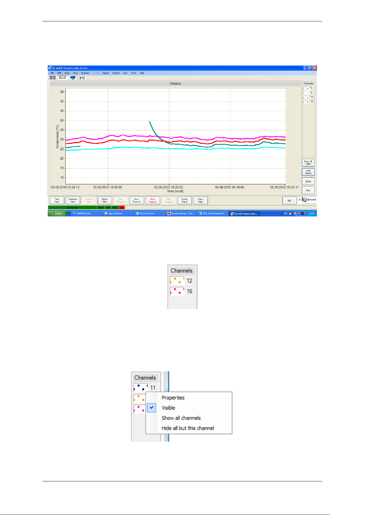
On default, the graphic output scales adaptively. I.e., the value range in the graphics
view corresponds with the currently measured maximum and minimum temperature
values. Optionally, a fixed scale can be selected.
Figure 4-25: TDS Graphics View – Channel Toolbar
In the right upper “Channels” field of the graphics screen, buttons for the currently active
channels are listed and assigned to the respective channel colour.
Figure 4-26: TDS Graphics View – Channel Buttons
You can toggle the visibility of channels in the graphics view by double-clicking the
channel buttons. Right-clicking the channel buttons activates a channel button context
menu for changing channel display parameters such as display colour, display of
additional information, etc.
Figure 4-27: TDS Graphics View – Channel Button Context Menu
TEMPRIS DataServer User Interface and Function Reference Page 56 of 80
Page 57
TEMPRIS User Manual
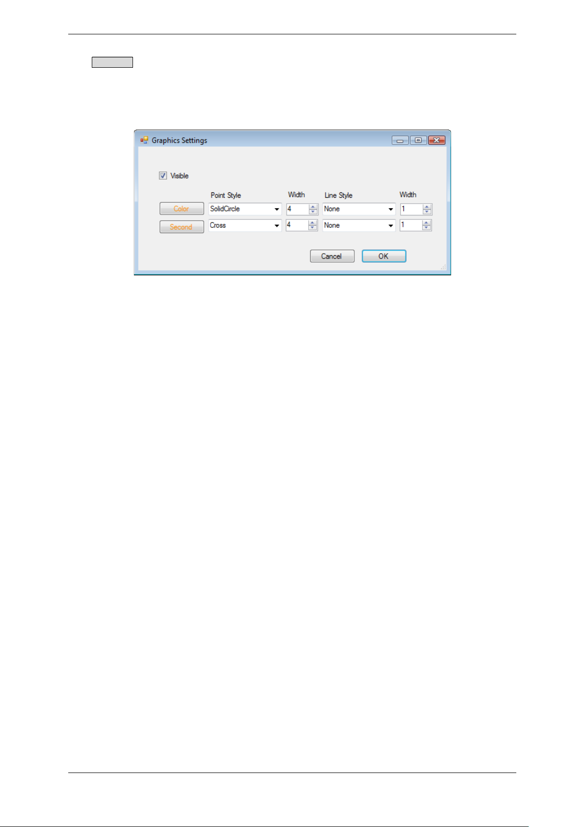
The Properties function of the channel button context menu activates a dialog for channel
display settings where you can toggle the visibility of the selected channel and set
channel display properties such as the colour, the “Point Style”, the point “Width”, the
“Line-Style” and the line “Width” for both the temperature plot display and the secondary
channel trace (signal quality “S/N” or antenna assignment; see below).
Figure 4-28: TDS Graphics View – Channel Display Settings
TEMPRIS DataServer User Interface and Function Reference Page 57 of 80
Page 58
TEMPRIS User Manual
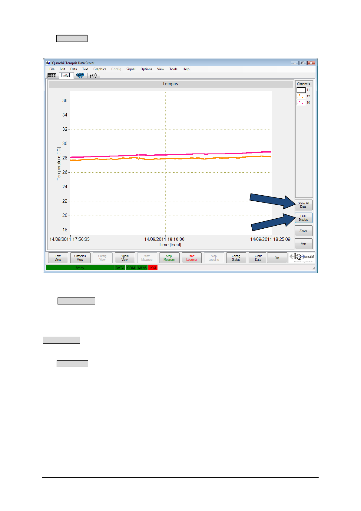
The Hold Display function is used to suspend (and resume) graphic updates (data recording
keeps running in the background):
Figure 4-29: TDS Graphics View – Show All Data
The Show All Data function displays all data recorded since the start of the monitoring
process (with compressed time axis if necessary).
Note
Show All Data can take a few moments to complete if the TEMPRIS DataServer holds a
large amount of measuring data.
The Hold Display function resumes the real-time display (with data for the last 30 minutes
being shown).
TEMPRIS DataServer User Interface and Function Reference Page 58 of 80
Page 59
TEMPRIS User Manual
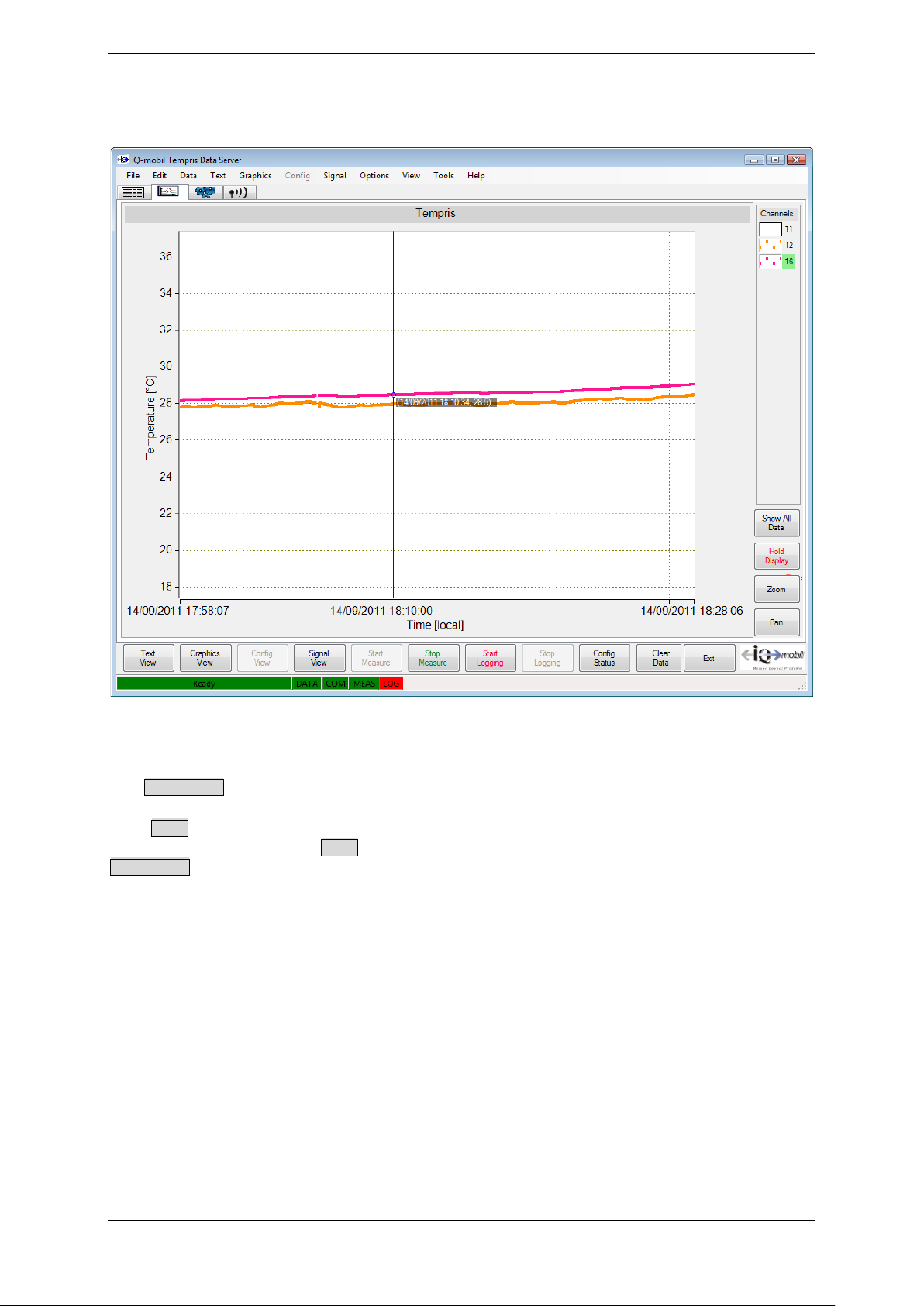
The graphics view also offers a marker function for displaying a cross-hair graphic cursor
with a time-value pair at the selected position:
Figure 4-30: TDS Graphics View – Marker Function
It is recommended to use the marker function only while real-time display is suspended.
Use Hold Display to suspend and resume real-time display.
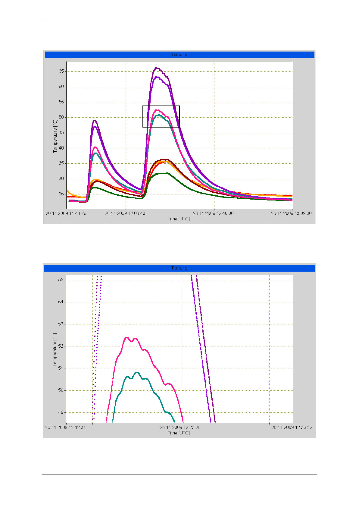
The Zoom function can be used for interactively selecting a zoom window. It is
recommended to use the Zoom function only while real-time display is suspended. Use
Hold Display to suspend and resume real-time display.
TEMPRIS DataServer User Interface and Function Reference Page 59 of 80
Page 60
TEMPRIS User Manual
The following screenshot illustrates a zoom window selection:
Figure 4-31: TDS Graphics View – Zoom Window Selection
The following screenshot shows the selected zoom window display:
Figure 4-32: TDS Graphics View – Zoom Window Display
TEMPRIS DataServer User Interface and Function Reference Page 60 of 80
Page 61
TEMPRIS User Manual
The Pan function can be used to move the graphic display in both x and y direction. It is
recommended to use the Pan function only while real-time display is suspended. Use Hold
Display to suspend and resume real-time display.
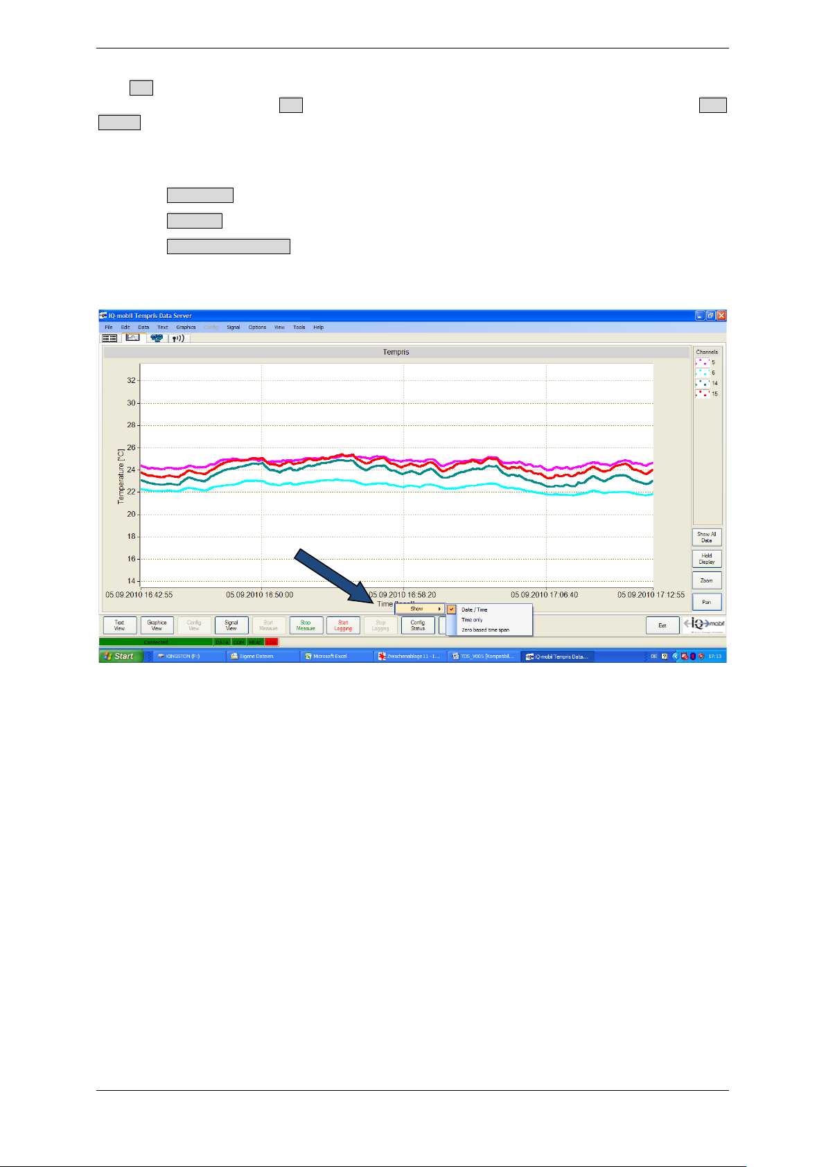
A right-click on the “Time” label activates a context menu with the following options:
• Date / Time - Display date and time
• Time only - Display time only
• Zero-based time span - Display relative time since the start of the measurement
Figure 4-33: TDS Graphics View – Time Label Settings
TEMPRIS DataServer User Interface and Function Reference Page 61 of 80
Page 62
TEMPRIS User Manual
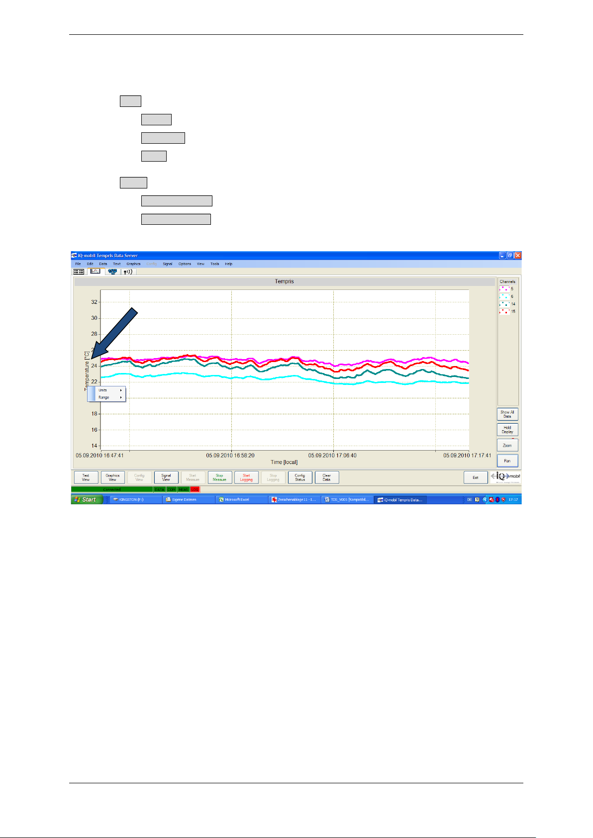
A right-click on the “Temperature” label activates a context menu with the following
options:
• Units - Temperature units selection:
• Celcius
• Fahrenheit
• Kelvin
• Range - Choice of ordinate scale:
• Automatic scaling (adaptive)
• Manual scaling (permanent, according to maximum/minimum value
selections)
Figure 4-34: TDS Graphics View – Temperature Label Settings
TEMPRIS DataServer User Interface and Function Reference Page 62 of 80
Page 63
TEMPRIS User Manual
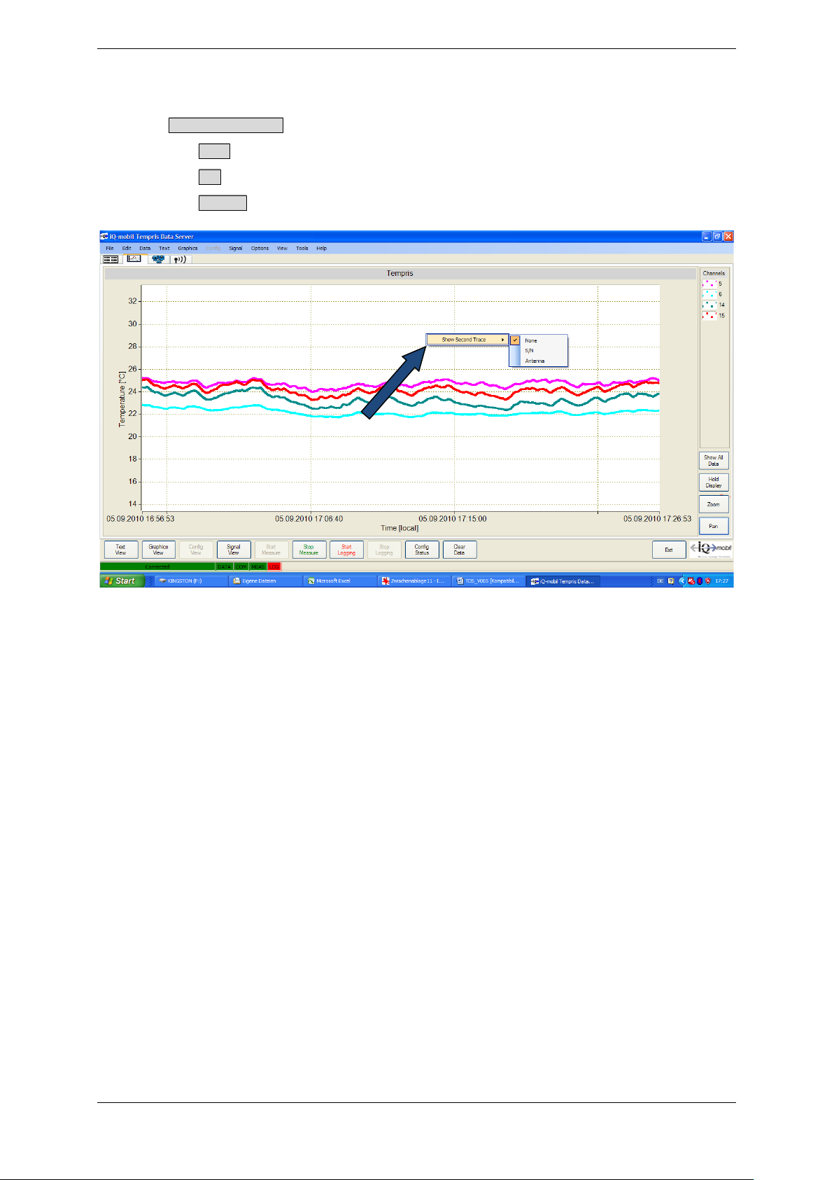
A right-click anywhere in the graphics area activates the following context menu:
• Show Second Trace – options for displaying an additional data graph:
• None – no additional data graph
• S/N – display signal-to-noise ratio (signal quality; see below) data graph
• Antenna – display assigned antenna data graph(s)
Figure 4-35: TDS Graphics View – Graphics Area Context Menu
TEMPRIS DataServer User Interface and Function Reference Page 63 of 80
Page 64
TEMPRIS User Manual
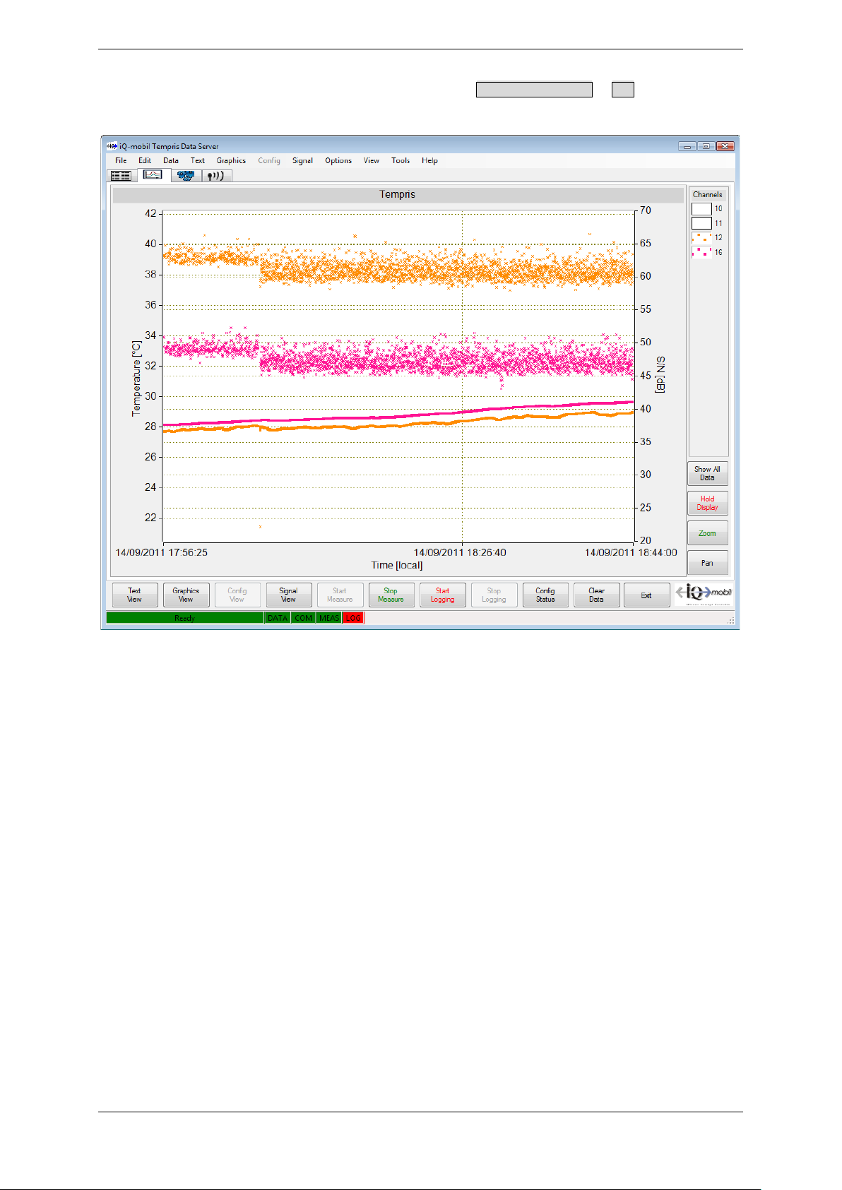
The following screenshot shows a graphic view with Show Second Trace – S/N activated (see
chapter 6.8 for more information on S/N):
Figure 4-36: TDS Graphics View – Show Second Trace S/N
TEMPRIS DataServer User Interface and Function Reference Page 64 of 80
Page 65
TEMPRIS User Manual
4.9 Signal View
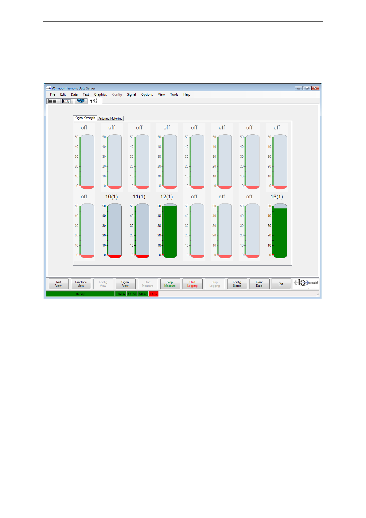
In the “Signal Strength” tab of the Signal View, the current data quality of the
incoming data is visualized. The data quality is displayed using S/N values (signal-tonoise ratio; spoken “S to N”), a logarithmic measure for the signal quality.
Figure 4-37: TDS Signal View – Signal Strength
TEMPRIS DataServer User Interface and Function Reference Page 65 of 80
Page 66
TEMPRIS User Manual
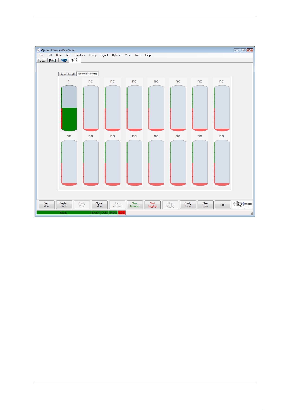
The “Antenna Matching” tab of the Signal View displays indicators for channel to
antenna matching quality.
Figure 4-38: TDS Signal View – Antenna Matching
TEMPRIS DataServer User Interface and Function Reference Page 66 of 80
Page 67
TEMPRIS User Manual
4.10 Clearing the Current Data Screen
The Clear Data command from the Data menu or the graphics view toolbar clears the
current graphic screen and restarts graphic output and/or display without affecting any
active data logging on the TEMPRIS interrogation unit.
4.11 Recording Incoming Measuring Data onto Log Files
The Start Logging and Stop Logging commands from the toolbar are used to activate and/or
deactivate the recording of incoming measuring data onto a log file.
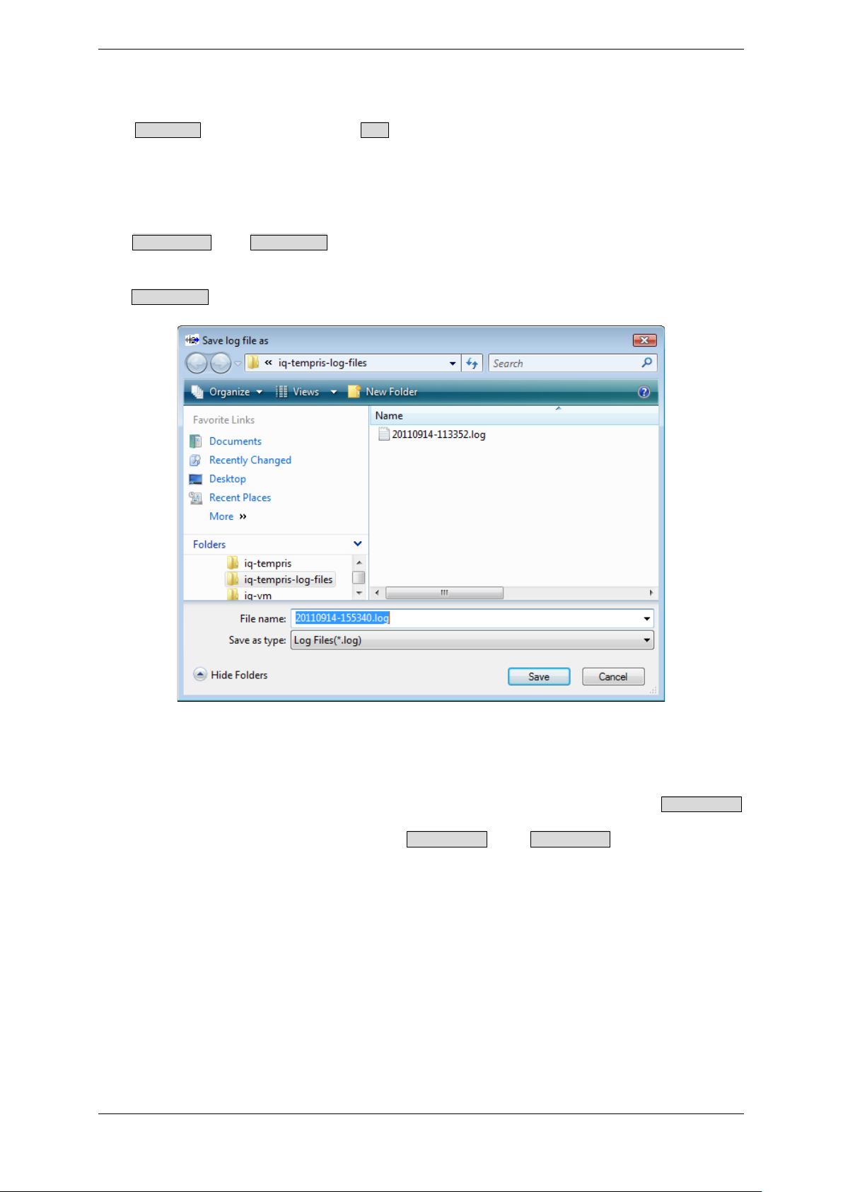
The Start Logging command activates a dialog for specifying the desired log file name:
Figure 4-39: Start Logging - Log File Name Selection
Note
Please make sure to specify a non-existing log file name to prevent the Start Logging
function from overwriting any existing log file with the same (default) log file name which
previously may have been created with Start Logging and Stop Logging during the same
TEMPRIS DataServer session.
TEMPRIS DataServer User Interface and Function Reference Page 67 of 80
Page 68
TEMPRIS User Manual
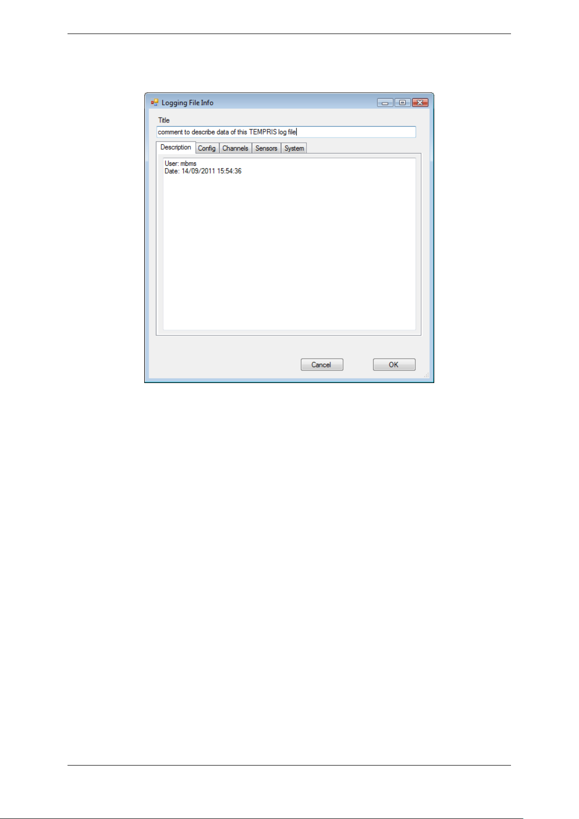
After specifying a log file name, the following dialog for specifying log file information is
activated:
Figure 4-40: Start Logging – Log File Info
The “Title” input field allows for a title for the logged data to be entered. The
“Description” text field allows for a descriptive text (notes, comments, etc.) for the
logged data to be typed in. This information is permanently stored in the log file header
of the log file and may be helpful when examining and/or processing the log file data at a
later stage.
TEMPRIS log files can become very large (several 100 MB) depending on the duration of
the measurement and/or the selected data rate. This may pose handling problems when
processing such large log files on computers with limited processor capacity, main
memory or hard disk space. We therefore recommend that you choose the data rate with
this in mind and according to your actual time resolution requirements.
Log files can be exported to CSV (“Comma Separated Values”) files for subsequent
processing in spread sheet applications such as Microsoft Excel.
TEMPRIS DataServer User Interface and Function Reference Page 68 of 80
Page 69
TEMPRIS User Manual
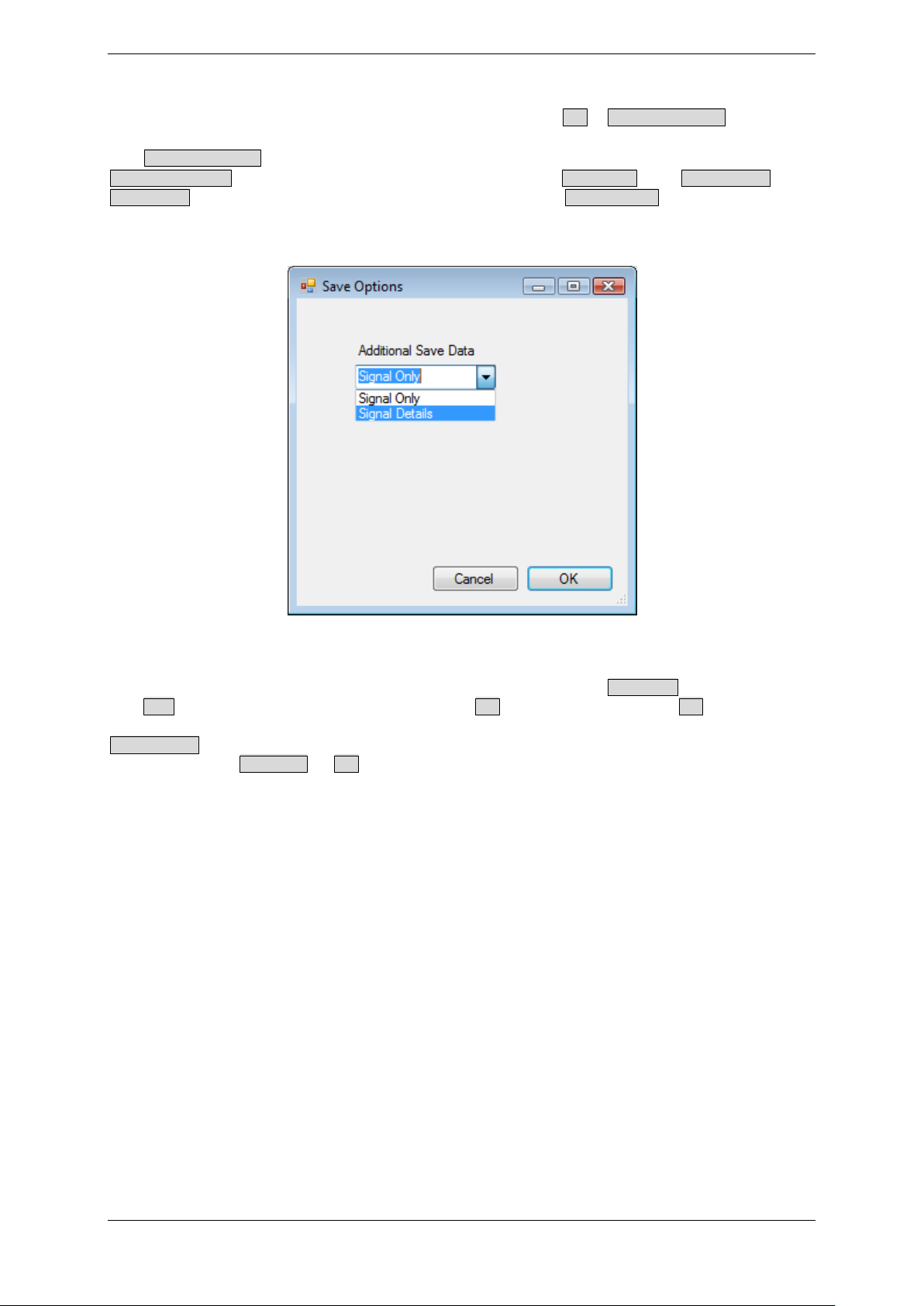
Since the measuring data is stored internally within the program during a measuring run,
a later permanent saving of data is also possible with the File – Save Current Data function.
The Save Current Data function saves the currently displayed data to a log file (/*.log). The
Save Current Data function offers you the choice between Signal Only and Signal Details. The
Signal Only option saves temperature data only. The Signal Details option saves the
temperature data and additional data such as S/N (signal-to-noise ratio, signal quality)
values.
Figure 4-41: Save Current Data
Please note that cached data is cleared if you use either the Clear Data command (from
the Data menu or the graphics view) or the Exit command (from the File menu or the
toolbar). At the beginning of a measurement, you should take the precaution of using the
Start Logging command to generate a log file as this provides a backup in case you
accidentally use Clear Data or Exit without having saved your measurement data.
TEMPRIS DataServer User Interface and Function Reference Page 69 of 80
Page 70
TEMPRIS User Manual
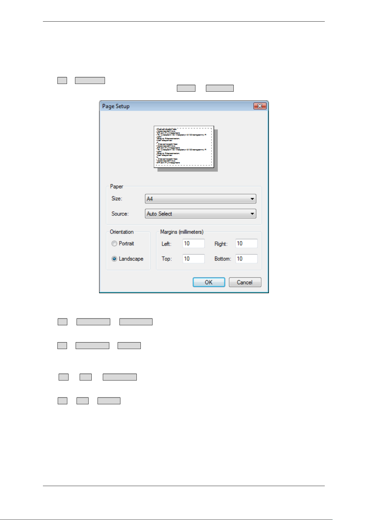
4.12 Print and Plot Output
The TEMPRIS DataServer program provides a number of functions for generating print
and plot outputs.
The File – Page Setup function activates a dialog for selecting printer settings such as paper
size, paper source/feed, page orientation ( Portrait or Landscape) and page/print margins:
Figure 4-42: Print Page Setup
The File – Print Preview – Current View function displays preview of the expected print result
for the total current screen. This function is available in all data view modes.
The File – Print Preview – Graphics function displays a preview of the expected print result of
the current graphics area without command / status bar. This function is only available in
graphics view mode.
The File – Print – Current View function prints the total current screen. This function is
available in all data view modes.
The File – Print – Graphics function prints the current graphics area without command and
status bar. This function is only available in only in graphics view mode.
TEMPRIS DataServer User Interface and Function Reference Page 70 of 80
Page 71
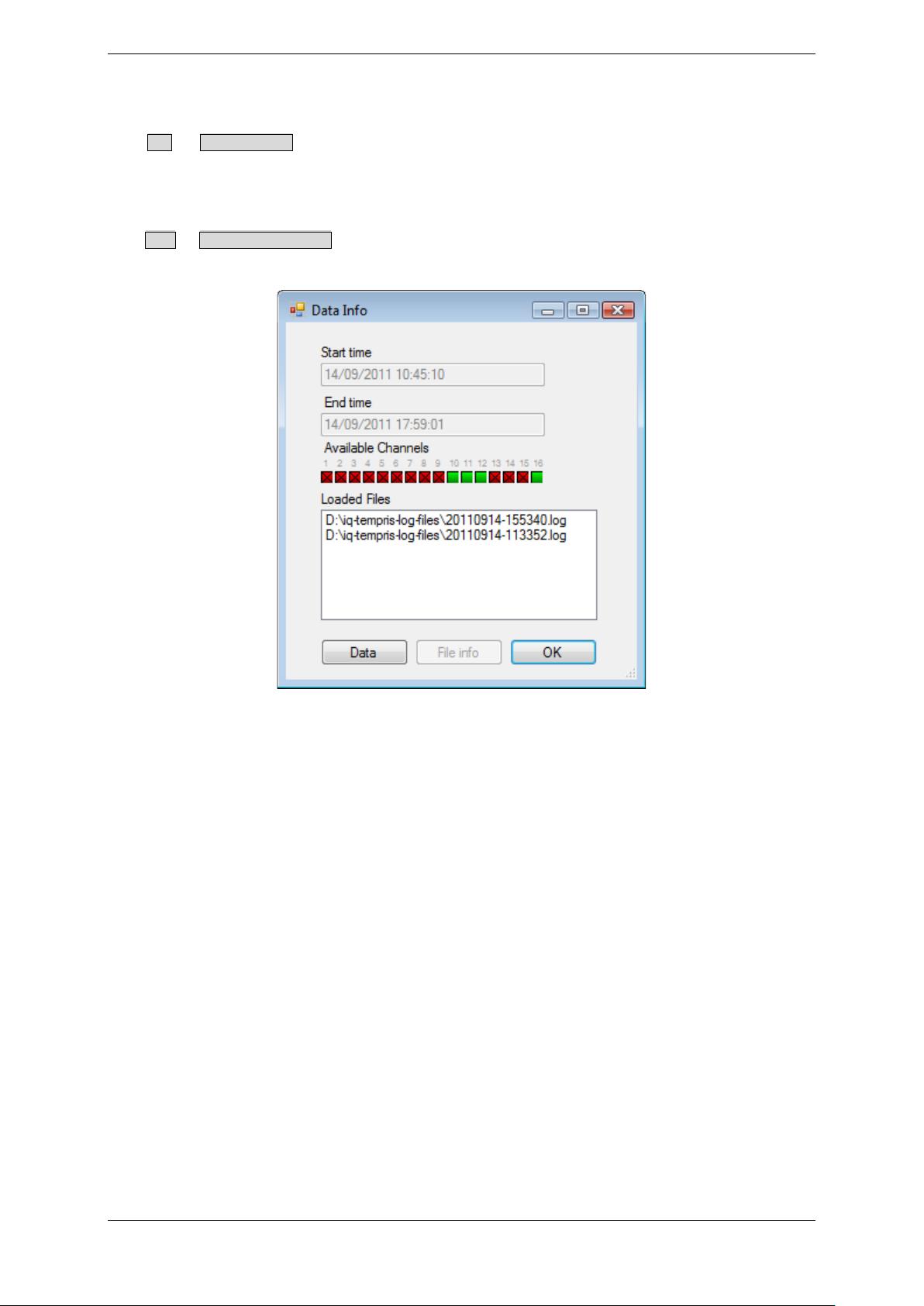
TEMPRIS User Manual
4.13 Loading Log Files for Offline Data Visualization
The File – Load Log File function can be used to load log files from previous TEMPRIS
measurements for offline processing (visualization, measurement with cross hairs, detail
view with zoom function, documentation with “Print”, etc.). If necessary, multiple log
files can be superimposed.
The Data – Loaded Log File Info function displays the names of the loaded log files together
with start and end time of the loaded data and an indication of the activated channels:
Figure 4-43: Loaded Log File Info
TEMPRIS DataServer User Interface and Function Reference Page 71 of 80
Page 72
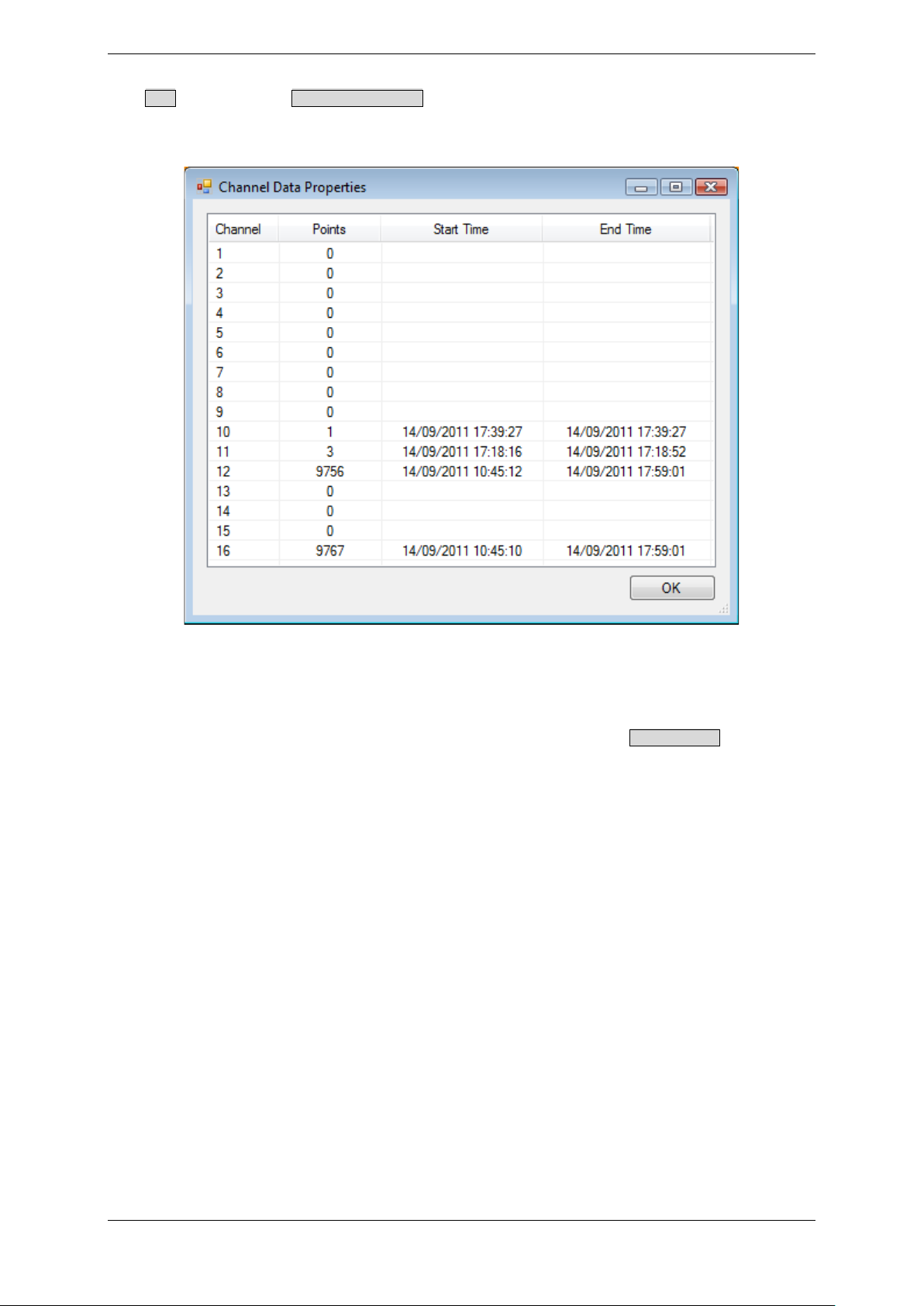
TEMPRIS User Manual
The Data button in the Loaded Log File Info dialog activates a channel data properties dialog
with additional log file information about stored channels, data volume, and recording
time.
Figure 4-44: Loaded Log File Info - Data
Note
The TEMPRIS interrogation unit needs not be connected for the Load Log File function to
work. I.e., you can use the TEMPRIS DataServer software on a PC or laptop without a
connection to a TEMPRIS interrogation unit to load and analyse TEMPRIS measurement
data from a previously stored TEMPRIS log file. We also make sure that the TEMPRIS log
file format is forward compatible. This means that your TEMPRIS DataServer software
can load TEMPRIS log files which were saved with older TEMPRIS DataServer versions.
TEMPRIS DataServer User Interface and Function Reference Page 72 of 80
Page 73
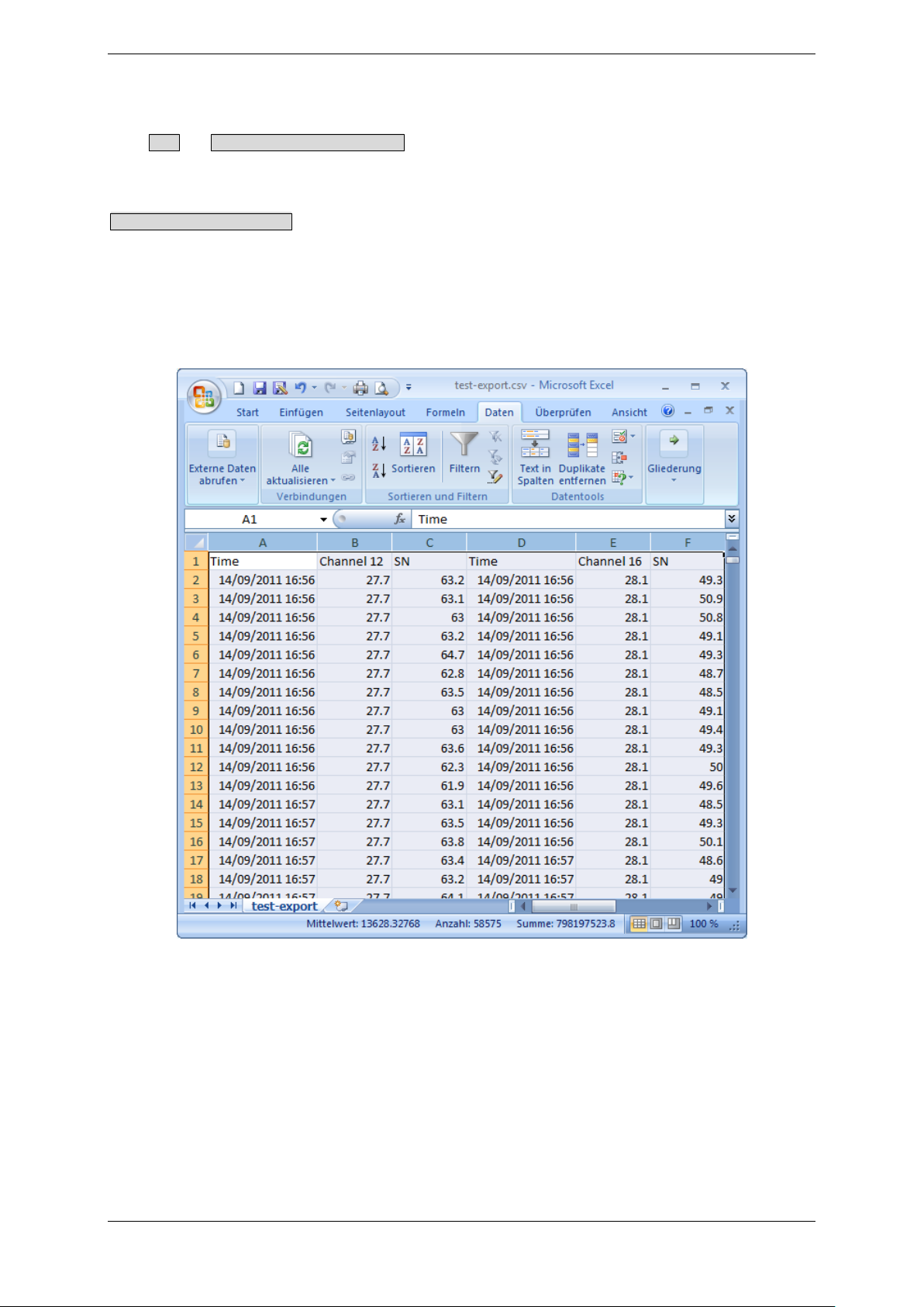
TEMPRIS User Manual
4.14 Data Export to CSV
The Data – Export Current Data to CSV function is used to export the currently loaded
measuring data to a CSV file (CSV = “Comma Separated Values”) for further processing
in spread sheet applications such as Microsoft Excel.
Export Current Data to CSV generates two CSV file columns for each active channel/sensor.
The first of these columns contains the timestamp (in country-specific format), and the
second column contains the temperature value in country-specific decimal notation. Up to
16 channels are exported with each channel having its own timestamp column.
The following screenshot shows a Microsoft Excel session with an imported TEMPRIS CSV
file.
Figure 4-45: TEMPRIS CSV Data in Microsoft Excel
TEMPRIS DataServer User Interface and Function Reference Page 73 of 80
Page 74

TEMPRIS User Manual
The Export Current Data to CSV function exports date/time values and numerical values using
the format which is currently activated through your Windows Control Panel – Regional and
Language Options settings. Certain Microsoft Excel versions are limited to a maximum of
32000 data rows per spread sheet. To overcome this potential problem you can either log
your TEMPRIS data at a reduced data rate (see 6.5 Configuring the system settings,
“Measurement Interval(s)”) or create appropriate excerpts from the data stock using the
File – Save Current Data function.
The TEMPRIS interrogation unit needs not be connected for the Export to CSV function to
work. I.e., you can use the TEMPRIS DataServer software on a PC or laptop without a
connection to a TEMPRIS interrogation unit to load TEMPRIS measurement data from a
previously stored TEMPRIS log file with the Load Log File function and export this data to a
CSV file with the Export to CSV function.
For an easier handling of large log files, you can use the compression tools Compress Log
file and Decompress Log file from the Tools menu.
TEMPRIS DataServer User Interface and Function Reference Page 74 of 80
Page 75
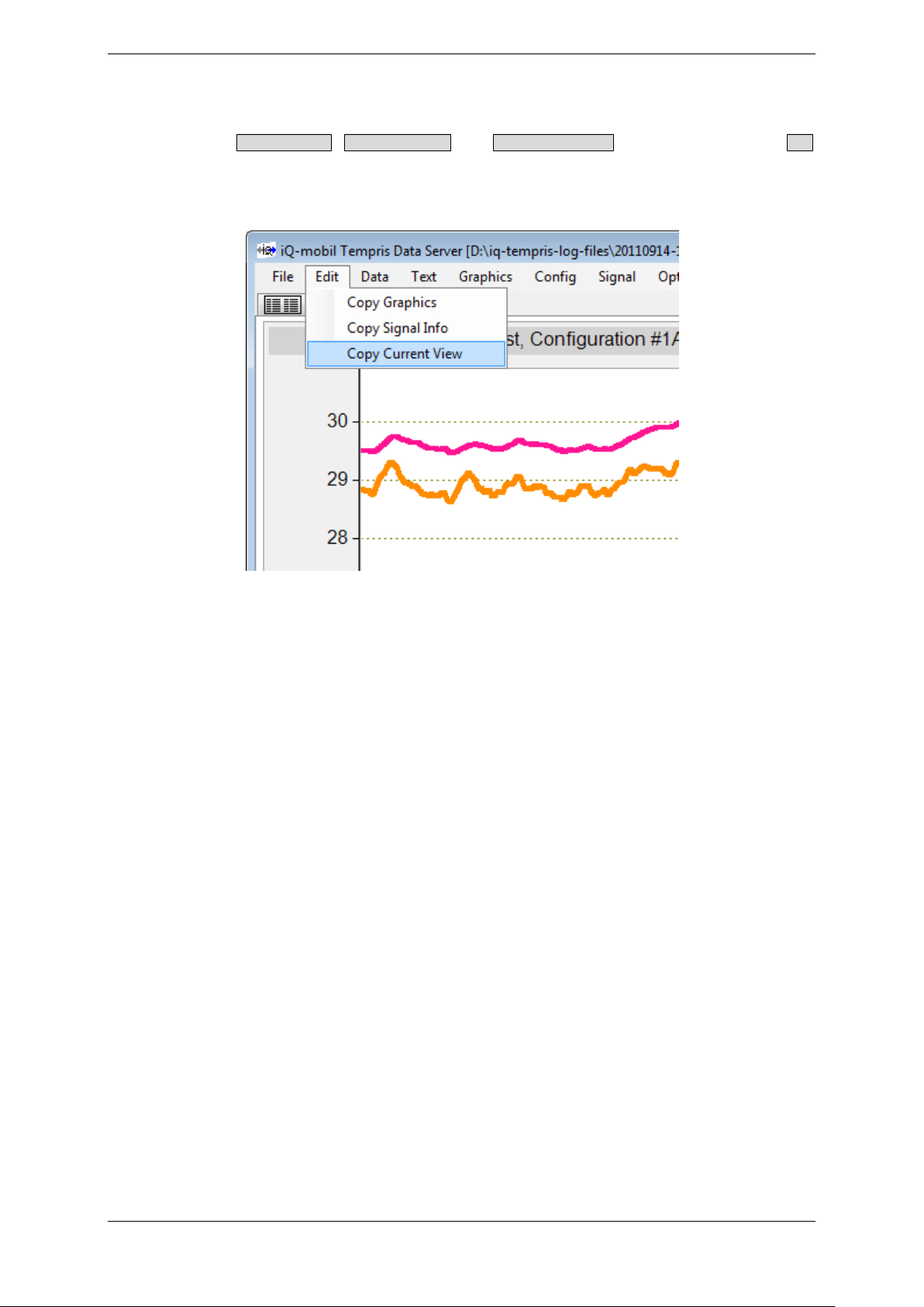
TEMPRIS User Manual
4.15 Copying Screens to the Windows Clipboard
The commands Copy Graphics, Copy Signal Info and Copy Current View commands from the Edit
menu can be used to copy the corresponding screens as bitmap image (without the
actual data) to the Windows Clipboard for further processing (pasting/inserting) in word
processor and desktop publishing applications such as Microsoft Word.
Figure 4-46: Copy Screen to Clipboard
TEMPRIS DataServer User Interface and Function Reference Page 75 of 80
Page 76
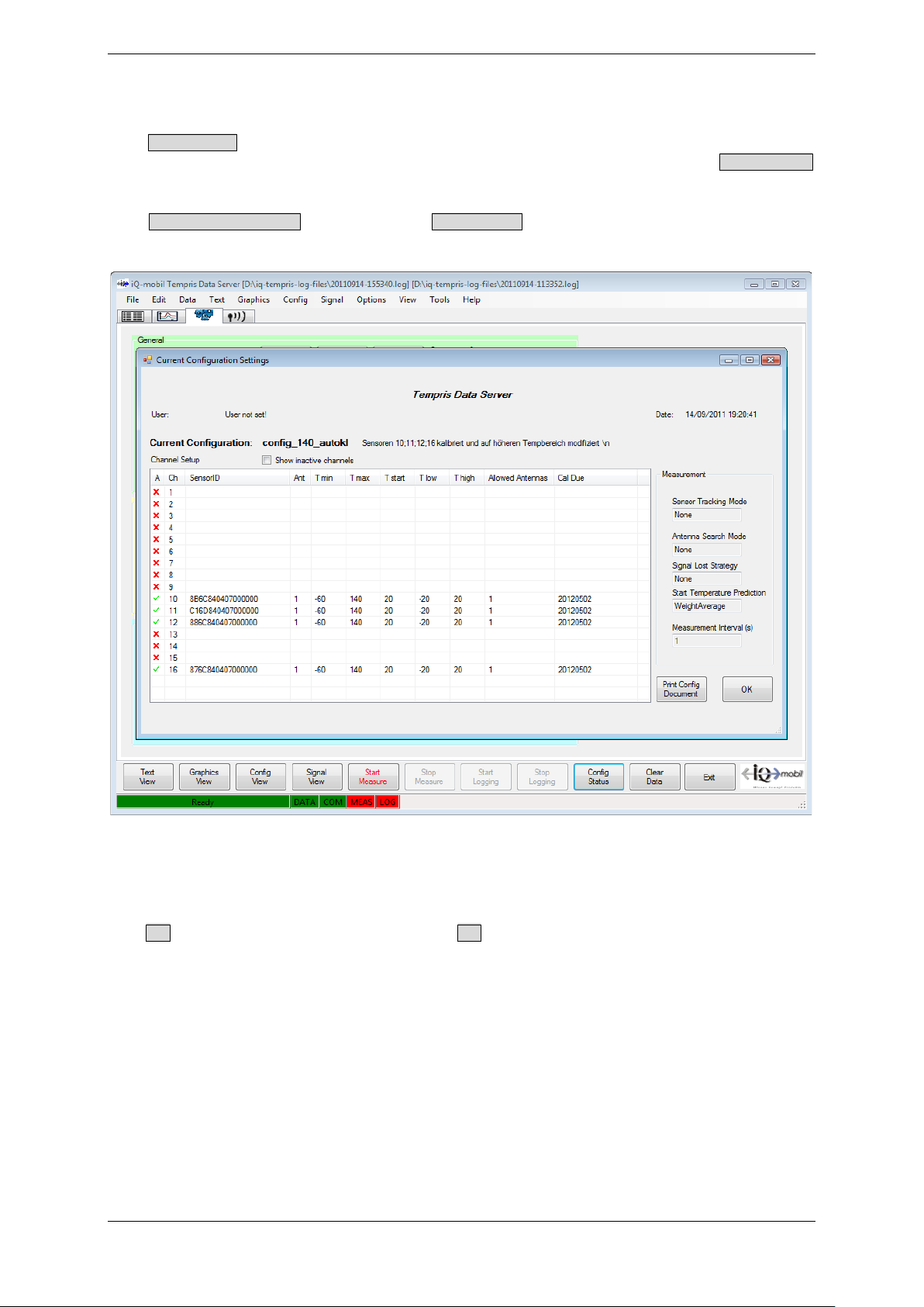
TEMPRIS User Manual
4.16 Retrieving the Current Configuration Settings
The Config Status command toolbar button retrieves and displays the current TEMPRIS
DataServer and TEMPRIS interrogation unit configuration status. The Config Status
command can only be activated if a connection to a TEMPRIS interrogation unit is active.
The Print Config Document button in the Config Status window can be used to print the
configuration status.
Figure 4-47: Current Configuration Settings
4.17 Exiting the TEMPRIS DataServer
The Exit command from the toolbar or the File menu is used to terminate the TEMPRIS
DataServer session.
Note
Exiting the TEMPRIS DataServer software does not affect the activities of the TEMPRIS
interrogation unit. I.e., the TEMPRIS interrogation unit keeps supplying a connected PLC
/ SCADA system with data, even though the TEMPRIS DataServer program which started
the measurement on that TEMPRIS interrogation unit has been closed.
TEMPRIS DataServer User Interface and Function Reference Page 76 of 80
Page 77
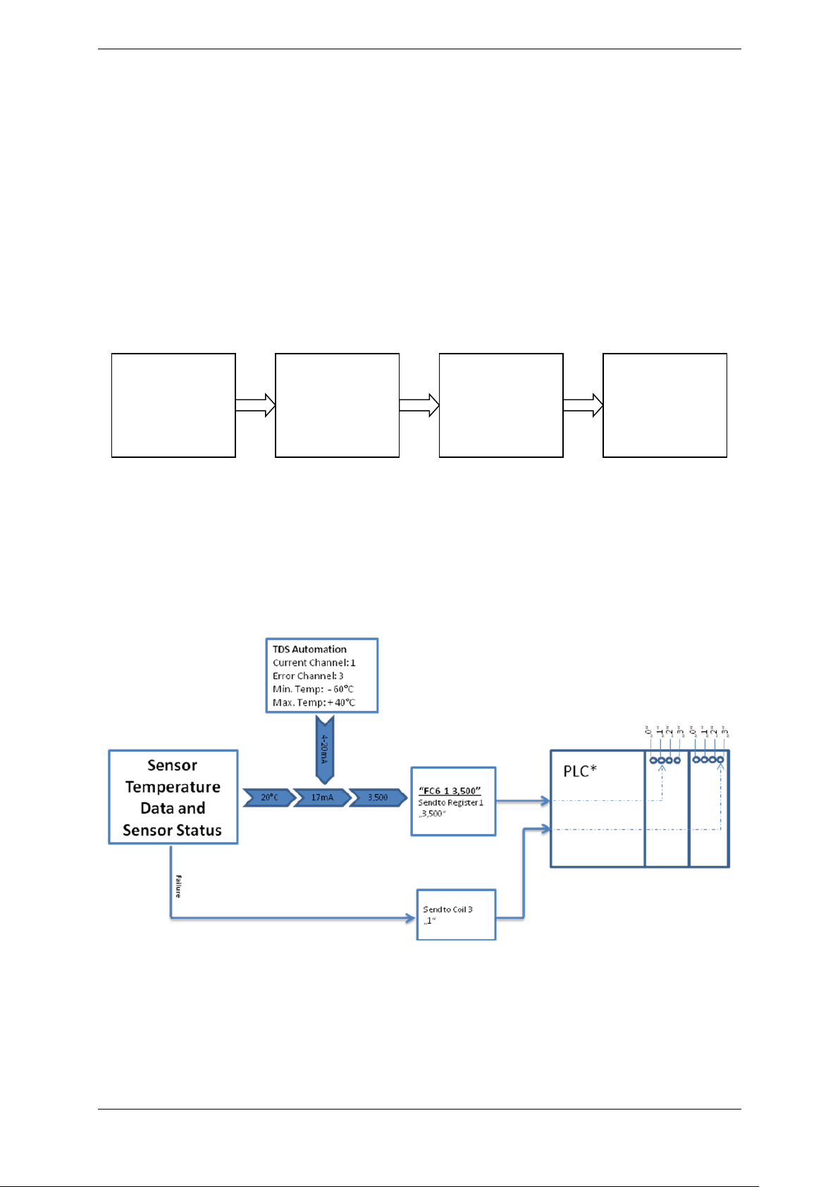
TEMPRIS User Manual
Modbus
552/000-200)
5 TEMPRIS Options
5.1 Modbus TCP/IP Interface
The TEMPRIS system comes with a Modbus TCP/IP interface. The TEMPRIS Modbus
TCP/IP interface is integrated to the TEMPRIS IRU-2 interrogation unit and can be
configured with the TEMPRIS DataServer software.
The TEMPRIS Modbus TCP/IP interface allows for TEMPRIS data to be transmitted over 420mA or 0-20mA current loops to Programmable Logic Controllers (PLCs) for processcontrol use.
The following block diagram shows a typical setup of a TEMPRIS Modbus TCP/IP to PLC
interface.
TEMPRIS
Interrogation
Unit (IRU-2)
Ethernet
TCP/IP
TCP/IP
Coupler
(e.g., Wago 750-
341)
4-20mA or
0-20mA / PLC
(e.g., Wago 750-
Figure 5-1: TEMPRIS Modbus TCP/IP to PLC Interface Setup
The following figure illustrates the principle of the TEMPRIS temperature sensor data and
sensor status output to the PLC. The TEMPRIS sensor temperature value is transmitted
with “Write Single Register” (function code FC6) or “Write Multiple Registers” (function
code FC16) to the Modbus register. The TEMPRIS sensor status flag (“Sensor missing/not
found”) is transmitted with “Write Single Coil” (function code FC5) or “Write Multiple
Coils” (function code FC15) to the Modbus “coil”.
Figure 5-2: TEMPRIS Sensor Data and Sensor Status Output to PLC
TEMPRIS Options Page 77 of 80
Page 78
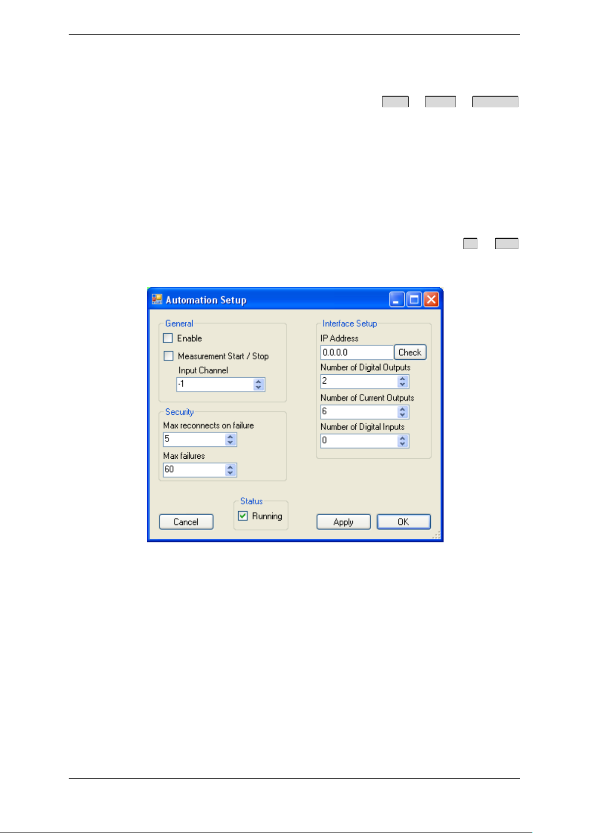
TEMPRIS User Manual
5.1.1 TEMPRIS Modbus TCP/IP Interface Setup
General Modbus interface settings are carried out through the TEMPRIS DataServer
“Automation Setup” dialog which can be activated with the Config – System – Automation
function. The “Automation Setup” dialog provides controls for:
• setting the Modbus “IP Address”,
• specifying the “Number of Digital Outputs” for transmitting TEMPRIS status
flags to Modbus “Coils”,
• specifying the “Number of Current Outputs” for transmitting temperature
values to Modbus “Registers”,
• enabling/activating the TEMPRIS Modbus TCP/IP interface.
The following figure shows the “Automation Setup” dialog. When pressing the OK or Apply
button, the “Automation Setup” interface configuration is not only activated but also
saved to the TEMPRIS interrogation unit for future use.
Figure 5-3: TEMPRIS DataServer Config – System – Automation
TEMPRIS Options Page 78 of 80
Page 79

TEMPRIS User Manual
5.1.2 TEMPRIS Modbus TCP/IP Channel Configuration
The “Automation” tab in the Channel Properties dialog of the TEMPRIS DataServer is used
for the configuration of channel-specific Modbus outputs. The Channel Properties dialog for a
specific TEMPRIS channel is activated by clicking the channel button in the “Channel /
Antenna Configuration” block of the TEMPRIS DataServer “Config View”.
Channel Properties dialog controls:
• “Current Output Index”
Sets the Modbus “Register” for transmitting the channel/sensor temperature
values. The “Current Output Index” is zero-based and limited by the “Number
of Current Outputs” specified through “Automation Setup” (see above).
• “T min” and “T max”
Specifies the channel temperature range for the “Current Output Index” to be
mapped to the 4-20mA current loop range.
(Typical setting for lyophilisation processes: T
= -60ºC; T
min
• “T error”
Specification of an error temperature value to be transmitted if no valid channel
temperature value is available.
= 40 ºC)
max
• “Error Output Index”
Sets the Modbus “Coil” for transmitting “Sensor missing / not found” status
flags. The “Error Output Index” is zero-based and limited by the “Number of
Digital Outputs” specified through “Automation Setup” (see above).
• “4-20mA”
Current loop range selection. Tick “4-20mA” box for 4-20mA range, or leave
box unticked for 0-20mA range.
TEMPRIS Options Page 79 of 80
Page 80
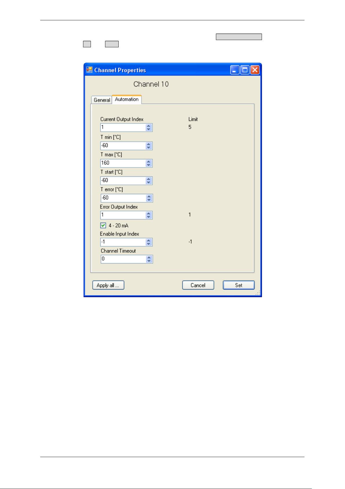
TEMPRIS User Manual
The following figure displays the “Automation” tab of the Channel Properties dialog. When
pressing the OK or Apply button, the “Automation” channel properties are not only
activated but also saved to the TEMPRIS interrogation unit for future use.
Figure 5-4: TEMPRIS DataServer Channel Properties - Automation
TEMPRIS Options Page 80 of 80
 Loading...