

Page 1
OPA 300R
Packaged Reverse Cycle
Air Cooled Air Conditioner
GENERAL
This OPA 300R unit must be installed in
accordance with all national and local
safety codes.
CONFIGURATIONS
The OPA 300R is supplied in one of three
standard configurations :
1. Horizontal supply/return air with
mounting rails,
2. Downward supply air with mounting
rails, or
3. Downward supply air with plinth mount.
REFRIGERATION SYSTEM
General
The refrigeration system has been charged
with 6.6 kg each of HCFC-22 (R22)
refrigerant. Tapping points are provided to
measure discharge and suction operating
pressures.
Compressors
The compressors are directional scroll type.
On commissioning, the compressors must
be checked for correct rotation (refer Start
Up Procedure).
The compressor is fitted with an adjustable
anti-rapid cycle timer which provides a
delay 'on break' (i.e. stop-to-start).
ECONOMISER (Option)
If the outdoor air heat content or
temperature is below that of the return air,
the fresh air damper opens and the return
air damper closes to provide the first stage
of cooling. The compressor(s) will then
operate to provide more cooling if required.
INSTALLATION
Unpacking
Units configured with Downward supply air
and mounting rails, have their spigots
shipped loose inside the return air cavity.
Positioning
Refer to dimension diagrams for minimum
clearances. If multiple units are to be
placed side-by-side then allow at least 2 m
between coil faces.
Mounting
The unit should be fastened to a firm flat
horizontal base using the holes supplied in
the mounting rails. Refer to figure 4 for
plinth mount details.
When the unit is being installed on a roof it
is recommended that the unit is installed on
a substantial structure with vibration
isolating springs beneath the unit. These
springs are not supplied with the unit. Two
channels are provided under the base for
spring mounts or bolting down.
Flexible duct connections are
recommended between the supply and
return ducts and the unit.
Condensate Drain
The condensate drain should be 'U' trapped
outside the unit. The trap should have a
Downward height of at least 100 mm. The
drain should have a slope of at least 1 in 50
and must not be piped to a level above the
unit drain pipe (see figure 5).
Electrical Requirements
Electrical work must be done by a qualified
electrician. The outdoor unit must be wired
directly from a distribution board by means
of a circuit breaker or H.R.C. fuse, and a
mains isolator provided - preferably close to
the unit.
Note: DO NOT USE REWIRABLE FUSES.
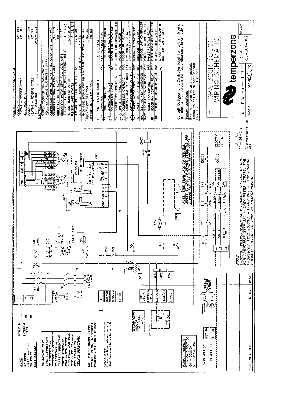
The OPA 300 is provided with a 24V AC
control circuit for a thermostat, on/off switch
and/or time clock.
The control transformer 240V primary
voltage is used for countries with 230-240V
power supply. For countries with supply
voltages 200-220V, change the primary
voltage on the transformer to 208V.
Standard units are suitable for use with
thermostats with either manual Heat/Cool
selection or automatic changeover subject to
the contact ratings of the thermostats.
A 24 hour power supply to the compressor
crank case heaters is required, otherwise the
warranty is void.
CHECK TESTS
1. Leave the on/off switch in the off position
and close the mains isolating switch.
A four hour delay period is required to
allow the crankcase heaters to drive any
liquid refrigerant out of the compressor oil.
2. Check that the shipping block beneath the
compressor has been removed and that
the compressor is secure on its mounts.
3. Check that all fan motors are free running.
4. Check that the thermostat is correctly
wired to the unit and is set at the desired
temperature.
5. Check that the air filters have been
correctly installed if fitted.
6. Check air diffuser dampers are open if
appropriate.
START UP PROCEDURE
Use the supplied Commissioning Sheet to
help you complete the following procedure:
1. After the four hour delay period has
expired, switch on the unit.
2. The compressor fitted is directional.
Check for correct rotation. If rotation is
incorrect the compressor will not pump, be
noisy, and will draw minimal current. To
correct motor rotation, change the phasing
at the main power terminal.
3. Check the supply voltage between each
phase and neutral.
4. Measure the current draw on each phase
to the compressor motor and measure the
current draw of each fan motor. Check all
readings against the specified values in
the wiring diagram.
Installation &
Maintenance
5. Fit gauges and measure the suction and
discharge pressures of both refrigeration
circuits.
6. Check that the outdoor air fan motors are
running smoothly.
7. Test the operation of the reversing valve
by running the unit in both the heating
and cooling mode.
8. Check the indoor unit's fan belt tension
after 20 mins of operation and adjust if
necessary (refer Commissioning Sheet).
9. Check the supply air flow at each outlet.
10.Check the tightness of all electrical
connections and sign the check label.
11.Touch up any outdoor unit paintwork
damage to prevent corrosion.
SETTING SUPPLY AIR FLOW
Consult OPA 300 Technical Data pamphlet
for details of airflow/duct static pressure, if
required.
If the indoor air returning to the unit is
regularly expected to be above 50%RH,
then the coil face velocity should be limited
to be 2.5 m/s or less (refer Air Handling
graph in Technical Data pamphlet).
High humidity levels can occur in tropical or
subtropical conditions, and/or when heavily
moisture laden fresh air is introduced.
Select a fan speed that avoids water carryover problems.
In a free blow or low resistance application,
beware of exceeding the fan motor's full
load amp limit (refer wiring diagram).
The indoor air fan motor is fitted with a
factory set adjustable pitch pulley.
Instructions for the adjustment of pulleys is
included on the back page of the supplied
Commissioning Sheet. One revolution of
adjustment is equal to approx. 7% change
in air volume flow rate.
OUTDOOR UNIT CONTROLLER (OUC)
The Outdoor Unit Controller (OUC) includes
a temperature sensing head pressure
control which enables the system to
compensate for outdoor ambient temperatures below 20°C on cooling cycle, and
above 15°C on heating cycle. The OUC also
has features which protect against icing or
overheating of coils, rapid cycling of the
compressor and loss of refrigerant charge.
If the outdoor unit fans take some time to
begin rotating when the system is powered
on, or they don't appear to be rotating
appropriately while the compressor is
running, consult the OUC label on the
electrical box. If necessary, refer to
temperzone for further diagnostic
information.
MAINTENANCE
Monthly
1. Check air filters, if fitted, and vacuum or
wash clean as necessary.
2. Check condensate drain for free
drainage.
Page 2
3. Check compressor compartment for oil
stains indicating refrigerant leaks.
Three Monthly (or every 1200 hrs of operation)
Check the indoor unit's fan belt tension and
adjust if necessary.
Six Monthly
1. Check the tightness of electrical
connections.
2. Check the tightness of fans, motor
mountings, pulleys and belt tension.
3. Check suction and discharge operating
pressures.
4. Replace indoor air filters (if fitted).
5. Check condensate drain for free
drainage.
Yearly
1. Check all refrigerant piping for chafing
and vibration.
2. Check the operation of electric heaters, if
fitted.
3. Check air supply at all diffusers.
4. Check for excessive noise and vibration
and correct as necessary.
5. Check fan and motor bearings and
lubricate or replace as necessary.
6. Check for insulation and duct damage
and repair as necessary.
7. Remove lint and dust accumulation from
outdoor coil fins.
8.Touch up any paintwork damage to
prevent corrosion.
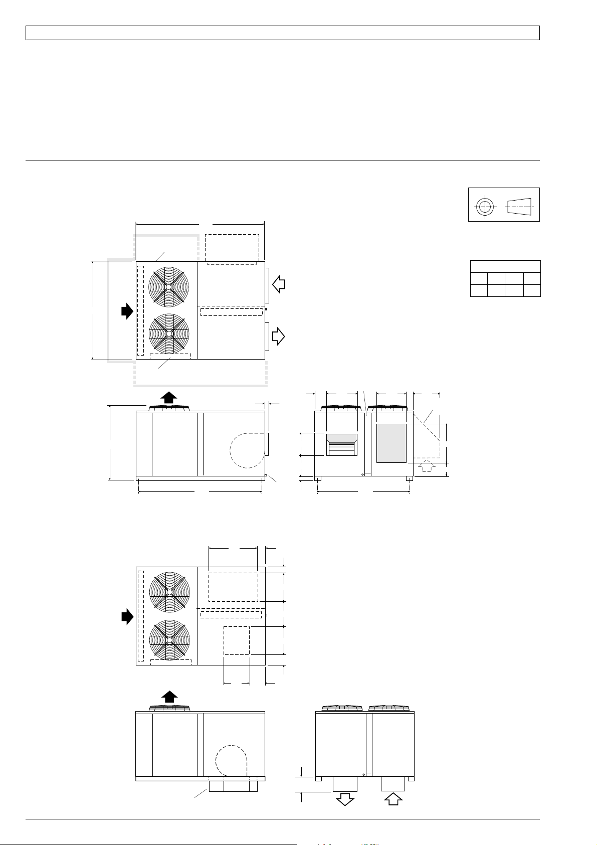
DIMENSIONS (mm)
Fig. 1 Horizontal Supply & Return Air / Mounting Rails
Version 1
1680
OPTIONAL
WEATHER
HOOD
1000 MIN. CLEARANCE
1560
MOUNTING CENTRES
X
RETURN
SUPPLY
Y
60
DRAIN
1" BSP
FEMALE
AIR
AIR
150
405
365
55
1475
W
OUTDOOR
AIR FLOW
500 MIN. CLEARANCE
Z
1330
1000 MIN. CLEARANCE
ACCESS
PANEL
ELECTRICAL
BOX
FILTER
ACCESS
PANEL
375
1360
MOUNTING CENTRES
425
105
POINT LOADS (kg)
WX Y Z
119 90 105 134
Net Weight 448 kg
Note : A 2 m clearance is
required above the
600
OPTIONAL
WEATHER
HOOD
770
225
OPA 300R
PROJECTION
Not to Scale
exhaust air fans
Fig. 2 Downward Supply Air / Mounting Rails
Version 2
OUTDOOR
AIR FLOW
ADD-ON
SPIGOTS
(SUPPLIED)
750
405
100
135
425
380
375
150
205
290
SUPPLY
& RETURN AIR
NOTE
The manufacturer reserves
the right to make changes in
specifications at any time
without notice or obligation.
Certified data is available on
request.
Note:
Supply and return air spigots
are shipped loose inside the
return air cavity.
Page 3
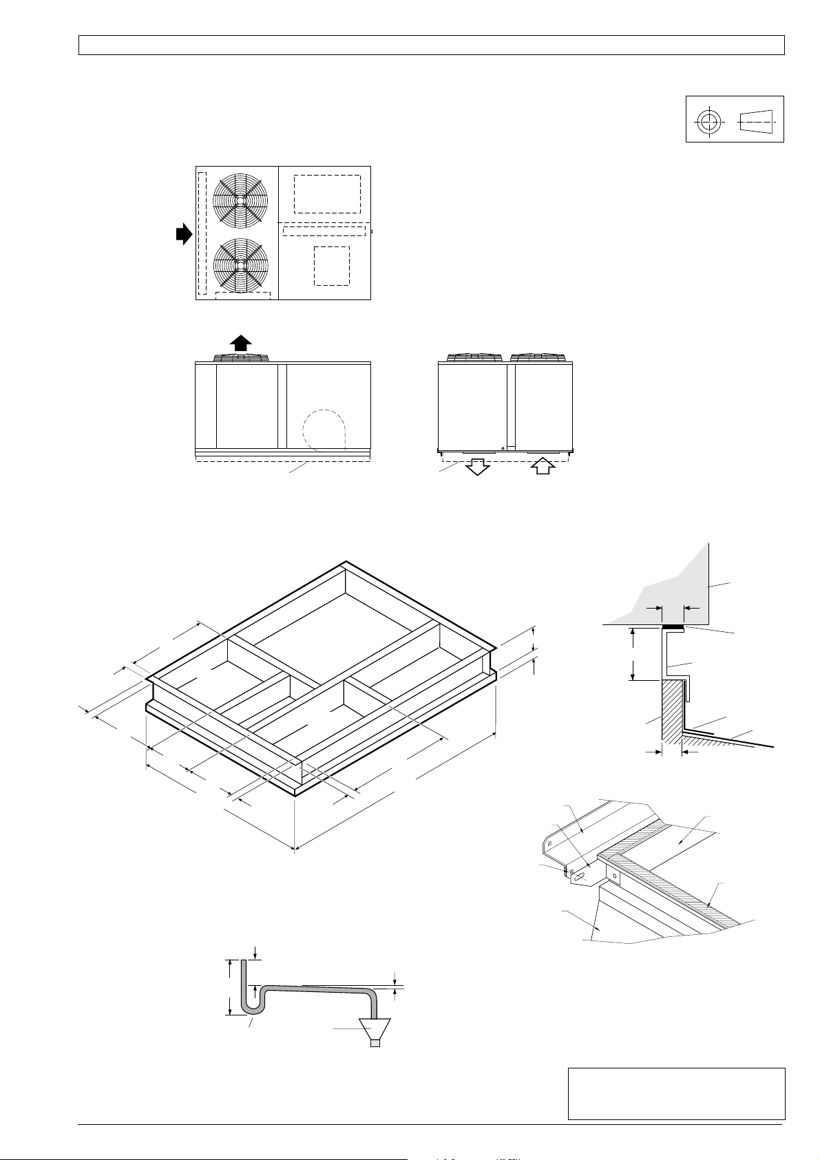
DIMENSIONS (mm)
Fig. 3 Downward Supply Air / Plinth Mounted
Version 3
OUTDOOR
AIR FLOW
OPA 300R
PROJECTION
Not to Scale
Note:
Refer to Fig.1 for overall dimensions and
Fig.4 for further plinth dimensions.
PLINTH PLINTH
Fig. 4 Roof Mounting Plinth (Kitset)
558
53
SUPPLY
AIR
53
447
321
471
1599
INSIDE
53
RETURN
AIR
SUPPLY
& RETURN AIR FLOWS
OPA UNIT
53
SEALER
125
60
125
STRIP
(SUPPLIED)
ROOF MOUNTING
PLINTH
FLASHING
MOUNTING
50
800
1344
INSIDE
53
HOLD DOWN BRACKET
HOLD DOWN BRACKET
SECURED TOGETHER
WITH NUT & BOLT
OPA UNIT’S
SUPPORT ANGLES
ANGLE &
MAXIMUM
ASSEMBLY
ROOF
PLINTH
INSEAL
Fig. 5 Condensate Drain
100 mm
200 mm
APPROX.
MINIMUM
'U' TRAP
OPEN
DRAIN
SLOPE
20 mm PER m
MINIMUM
(1 IN 50)
FLASHING
TYPICAL CORNER ASSEMBLY
NOTE
The manufacturer reserves the right to make
changes in specifications at any time without
notice or obligation. Certified data is available
on request.
This pamphlet replaces the previous
issue no. 2234 dated 06/03.
OUC added, wiring revision.
Page 4
04/05 Pamphlet No. 2487
© temperzone limited 2005
 Loading...